Performance Analysis of Intelligent Reflecting Surface Assisted NOMA Networks
Abstract
Intelligent reflecting surface (IRS) is a promising technology to enhance the coverage and performance of wireless networks. We consider the application of IRS to non-orthogonal multiple access (NOMA), where a base station transmits superposed signals to multiple users by the virtue of an IRS. The performance of an IRS-assisted NOMA networks with imperfect successive interference cancellation (ipSIC) and perfect successive interference cancellation (pSIC) is investigated by invoking 1-bit coding scheme. In particular, we derive new exact and asymptotic expressions for both outage probability and ergodic rate of the -th user with ipSIC/pSIC. Based on analytical results, the diversity order of the -th user with pSIC is in connection with the number of reflecting elements and channel ordering. The high signal-to-noise radio (SNR) slope of ergodic rate for the -th user is obtained. The throughput and energy efficiency of IRS-NOMA networks are discussed both in delay-limited and delay-tolerant transmission modes. Additionally, we derive new exact expressions of outage probability and ergodic rate for IRS-assisted orthogonal multiple access (IRS-OMA). Numerical results are presented to substantiate our analyses and demonstrate that: i) The outage behaviors of IRS-NOMA are superior to that of IRS-OMA and relaying schemes; ii) The -th user has a larger ergodic rate than IRS-OMA and benchmarks. However, the ergodic performance of the -th user exceeds relaying schemes in the low SNR regime; and iii) The IRS-assisted NOMA networks have ability to achieve the enhanced energy efficiency compared to conventional cooperative communications.
Index Terms:
Intelligent reflecting surface, non-orthogonal multiple access, imperfect SIC, 1-bit codingI Introduction
With the evolution of wireless communication networks, the fifth-generation (5G) and beyond has sparked a lot of concerns on high data rate, massive connectivity and spectrum utilization. The standards of 5G new radio have been completed currently and researchers are exploring the potential of emerging technologies for the next-generation communications [1, 2, 3]. As one of a promising multiple access candidate, non-orthogonal multiple access (NOMA) has the advantages in terms of spectral efficiency and link density. The distinctive feature of NOMA is that multiple users are allowed to occupy the same time/bandwidth resource blocks by utilizing the superposition coding scheme [4, 5]. It has been demonstrated that NOMA has ability to attain the better outage probability and ergodic rate compared to conventional orthogonal multiple access (OMA) [6, 7]. For the emerging sixth-generation (6G) communication networks, it becomes pivotal to support massive intelligent equipments with different requirements.
By extending NOMA to cooperative communications, cooperative NOMA was proposed in [8], where the nearby user with better channel condition was referred to half-duplex (HD) decode-and-forward (DF) relaying to transfer the signals for the distant users. To further enhance spectrum efficiency, the authors of [9, 10] investigated the outage behavior and ergodic rate of full-duplex (FD) cooperative NOMA, where the performance of FD NOMA outperforms HD NOMA in the low signal-to-noise radio (SNR). With the emphasis on green communication, the simultaneous wireless power transfer (SWIPT) based NOMA system was studied in [11], where the nearby user is viewed as DF relaying to forward the information. On the other hand, the authors of [12] analyzed the outage performance of a pair of users for amplify-and-forward (AF) relaying based NOMA systems. As a further development, the outage probability and ergodic performance of multiple users for AF NOMA systems were surveyed in [13, 14] over Nakagami- fading channels. Explicit insights for understanding the impact of FD mode on AF NOMA system, the authors of [15] characterized the outage behaviors of users with an opportunistic power split factor. Apart from the above works, NOMA technique has been widely applied to multiple communication scenarios. Regarding to safety applications, the secrecy outage probability of a pair of users was analyzed in [16] for NOMA networks by invoking stochastic geometry. With the objective of improving terrestrial user connections, the authors of [17] highlighted the trajectory design and power allocation of NOMA-based unmanned aerial vehicle networks. Additionally, the application of NOMA to satellite communications was investigated [18], where the ergodic capacity and energy efficiency are derived analytically.
In view of recent attentions, intelligent reflecting surface (IRS) has been as a prospective technology for 6G wireless communications [19]. More specifically, IRS is a low-cost planar array consisting of a large of passive reflecting elements, which is ability to reconfigure the wireless propagation environment through a programmable controller. In [20], the authors have proposed the concept of digital metamaterials, which manipulates the electromagnetic waves by coding ‘0’ and ‘1’ elements with control sequences (i.e., 1-bit coding). Recently, several application deployment scenarios of IRS-aided were introduced [21, 22] that: 1) Creating the line-of-sight (LoS) link between the BS and users via signal reflection; 2) Applying IRS to enhance the physical layer secrecy; 3) IRS-assisted to realize SWIPT for a large amount of devices; and 4) Deploying IRS on indoor walls, mall or stadium to provide the hot spot services and so on. The differences between IRS and active relaying such as DF relaying are mainly that IRS does not make use of any active transmitting components but only reflects the received signals to destination node through a passive array. Except these, IRS does not requires self-interference cancellation operations relative to full-duplex relaying which are costly to implement. Compared to DF relaying, the authors in [23] revealed that IRS has the ability to attain the higher energy efficiency on the condition of the required large rates. The achievable rate performance of IRS-assisted transmission outperformed that of DF relaying [24], when the size of the IRS is sufficiently larger. As a further advance, the authors surveyed the symbol error probability of IRS-aided wireless communication networks in a general mathematical framework [25]. When the eavesdropping channels were stronger than that of legitimate channels, the authors of [26] maximized the secrecy rate of legitimate users by designing the IRS’s reflecting beamforming. In [27], the energy efficient designs of IRS-based wireless communications were developed to guarantee individual link budget for users. Furthermore, the security performance of IRS-aided SWIPT was surveyed in [28], where the energy efficiency is maximized by combining the artificial noise, transmitting beamforming and phase shifts of IRS. For indoor scenarios, the authors of [29] maximized the channel capacity of indoor millimeter-wave by exploiting IRS’s reflection elements.
In light of the above discussions, researchers have begun to study the co-existence of IRS and NOMA [30, 31, 32]. Given the users’ rate, the authors in [30] analyzed the IRS reflection with discrete phase shifts for IRS-aided NOMA and OMA. On the condition of user ordering, the beamforming vectors and phase shift matrix were jointly optimized to reduce the transmitting power [31]. Furthermore, the authors of [32] maximized the minimum the achievable rates of users to ensure user’s fairness and improve the rate performance. In [33], the maximization of system throughput was formulated for IRS-NOMA by taking decoding order and reflection coefficients into consideration. For multi-antenna scenarios, the system sum rate of IRS-NOMA was improved by exploiting the fixed reflecting elements in [34]. To overcome the hardware limitations, a simple transmission of IRS-NOMA was designed in [35], where the outage probability of single user is derived with on-off control. As a further potential enhancement, the authors of [36] further studied the impact of coherent phase shifting and random phase shifting on outage behaviors for IRS-NOMA networks. In [37], the outage probability and ergodic rate of nearby user for IRS-NOMA were examined by designing the passive beamforming weights of IRS. Additionally, the secrecy outage performance of IRS-NOMA was evaluated in [38], where the use of IRS improves the security behaviors compared to conventional NOMA.
I-A Motivation and Contributions
As stated from conventional NOMA literatures that the decoding order of SIC-based at the users is mainly decided by the users’ channel power gains. However the directions of users’ channel can be manipulated by adjusting the IRS’s reflection signal amplitudes or phase shifts in IRS-assisted NOMA networks, where the combination of IRS and NOMA is capable of enhancing both the spectrum and energy efficiency of communication systems simultaneously. In [20], the digital metamaterial has ability to manipulate electromagnetic waves by programming different coding sequences. Consequently, research on using the thought of 1-bit coding scheme to analyze the performance of wireless communication systems is still imperative. Inspired by this treatise, we specifically investigate the performance of IRS-assisted NOMA with the aid of the thought of 1-bit coding, where an IRS can be regarded as a relay forwarding the information to multiple NOMA users. In addition, there are undesirable factors i.e., error propagation and quantization error in the SIC process for practical scenarios, which will result in decoding errors. It is significant to take the residual interference from SIC procedure into consideration. Hence we focus our attention on discussing the impact of residual interference from imperfect successive interference cancellation (ipSIC) on outage probability, ergodic rate and energy efficiency for IRS-NOMA networks. Additionally, the outage probability and ergodic rate of IRS-OMA with 1-bit coding are surveyed carefully. According to the above explanations, the primary contributions of this paper are summarized as follows:
-
1.
We derive exact and asymptotic expressions of outage probability for the -th user with ipSIC and perfect successive interference cancellation (pSIC) in IRS-NOMA networks. Based on theoretical analyses, the diversity order for IRS-NOMA is obtained. We demonstrate that the diversity orders of the -th user with ipSIC/pSIC are in connection with the number of reflecting elements of IRS and channel ordering. We also derive the closed-form expression of outage probability for IRS-assisted OMA.
-
2.
We confirm that the outage behaviors of IRS-NOMA are superior to that of IRS-OMA, AF relaying and FD/HD DF relaying. Furthermore, we investigate the impact of IRS’s deployment on the outage behaviors of IRS-NOMA networks. We observe that when the IRS is deployed closely to the BS, the enhanced outage performance is achieved. As the IRS departs from BS, the LoS deteriorates and the outage probability increases.
-
3.
We derive the exact expressions of ergodic rate of the -th user for IRS-NOMA networks. To obtain further more insights, we derive exact expression of ergodic rate for the -th user and obtain the high SNR slopes. We observe that the ergodic rate of the -th user converges to a throughput ceiling in the high SNR regime. As the number of reflecting elements increase, the ergodic performance of the -th user is becoming higher compared to relaying schemes. We also derive exact expression of ergodic rate for IRS-OMA.
-
4.
We study the throughput and energy efficiency of IRS-NOMA networks in both delay-limited and delay-tolerant transmission modes. For delay-limited transmission mode, the energy efficiency of IRS-NOMA outperforms that of IRS-OMA and converge to a constant value at high SNRs, while the IRS-NOMA and IRS-OMA achieve the larger energy efficiency than AF relaying and FD/HD DF relaying. In delay-tolerant transmission mode, the energy efficiency of IRS-NOMA is much larger than that of these benchmarks.
I-B Organization and Notations
The rest of this paper is organized as follows. In Section II, the network model and transmission formulation are introduced in detail. In Section III, new exact expressions of outage probability for IRS-NOMA are derived. Then the ergodic rates of IRS-NOMA are investigated in Section IV. At last, the numerical results are presented to verify theoretical analyses in Section VI and followed by concluding remarks in Section VII. The proofs of mathematics are collected in the Appendix.
The main notations used in this paper are shown as follows. denotes expectation operation. and denote the probability density function (PDF) and cumulative distribution function (CDF) of a random variable , respectively. The superscripts stand for the conjugate-transpose operation. diag represents a diagonal matrix. denotes the Kronecker product. is a identity matrix.
II Network Model
II-A Network Descriptions
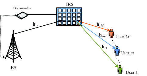
Considering an IRS-assisted NOMA communication scenario as illustrated in Fig. 1, in which a base station (BS) sends the signals to terminal users with the assistance of an IRS. Assuming that the direct links between BS and users are assumed strongly attenuated and the communication can be only established through the IRS [23, 27]. More specifically, the practical application of urban district scenarios can be supported by IRS-NOMA networks, where the communications between BS and users are blocked by the high-rise buildings. To provide the straightforward analyses, we assume that the BS and users are equipped single antenna, respectively111 It is noteworthy that multiple antennas equipped at the BS and user nodes will further enhance the performance of IRS-NOMA networks, which is set aside for our future treatise.. The IRS is mounted with reconfigurable reflecting elements, which can be controlled by the communication oriented software. Additionally, the complex online control and signal processing operations are required for IRS-NOMA, but it is beyond the scope of this paper. The complex channel coefficient between the BS and IRS, and between the IRS and users are denoted as and , respectively. In urban district scenarios, there are obstacles that can scatter a large number of radio signals. At this moment, the wireless links considered in IRS-NOMA networks are modeled as Rayleigh fading channels and our future work will relax this idealized simplifying assumption. These wireless links are perturbed by additive white Gaussian noise (AWGN) with the mean power simultaneously. Without loss of generality, the effective cascade channel gains from the BS to IRS and then to users are ordered as [39, 7], where is a diagonal matrix, and denote the fixed reflection amplitude coefficient and the phase shift of the -th reflecting element of the IRS, respectively [21, 35]. We assume that the channel state information of all wireless channel are perfectly available at the BS. The imperfect channel state information is more suitable for evaluating practical scenarios, which will be set aside in our future work. Note that the IRS can be deployed at both low and high frequency bands, but it has greater advantages in the high frequency bands, which is conducive to coverage enhancement [40, 41]. In this manuscript, the low frequency bands are taken into account for IRS-NOMA systems seriously.
II-B Signal Model
The BS sends the superposed signals to users by the virtue of an IRS. Hence the received signal reflected by IRS at the -th user is given by
| (1) |
where is assumed to be normalised the unity power signal for the -th user, i.e., . The -th user’s power allocation factor satisfies the relationship with , which is for the sake of user fairness. The optimal design of power allocation coefficients between users will further heighten the performance of NOMA networks, but it is beyond the scope of this paper. denotes the normalized transmission power at the BS. , where denotes the complex channel coefficient from the BS to the -th reflecting element of IRS. , where denotes the complex channel coefficient from the -th reflecting element of IRS to the -th user. denotes AWGN at the -th user.
On the basis of NOMA principle, the received signal-to-interference-plus-noise ratio (SINR) at the -th user to detect the -th user’s information is given by
| (2) |
where denotes the transmit SNR and . More precisely, and denote the pSIC and ipSIC operations. Without loss of generality, assuming that the residual interference from ipSIC is modeled as the Rayleigh fading and corresponding complex channel coefficient is denoted by .
After striking out the previous users’ signals with SIC, the received SINR at the -th user to detect its own information can be given by
| (3) |
II-C IRS-NOMA with 1-bit Coding
From the perspective of practical communication applications, continuously changing the reflection amplitude and phase shift of each IRS’s element is beneficial to enhance the network performance. This alternative implement needs the accurate design and expensive hardware architecture, which will result in the higher cost of IRS. To facilitate implement and analysis, 1-bit coding scheme is selected to achieve the discrete amplitude/phase shift levels for IRS-assisted NOMA networks [20, 35], where the elements of diagonal matrix are replaced with 0 or 1. It is the scalable and cost-effective solution with the number of reflecting elements becomes larger.
Assuming that the number reflecting elements of IRS are equal to , i.e., , where and are integers. Define , where is a column vector of all ones with . The -th column of is denoted by with and for . As a result, the SINRs of (2) and (3) can be maximized by randomly choosing one column i.e., from and rewritten as
| (4) |
and
| (5) |
respectively, where and are the diagonal matrix with its diagonal elements obtained from and . The following network performance of IRS-NOMA is discussed with 1-bit coding scheme.
II-D IRS-OMA
In this subsection, the IRS-OMA scheme is regarded as one of the benchmarks for comparison purpose, where an IRS is deployed to assist in the transmission from the BS to a user . On the condition of the above assumptions, the maximized SNR of user with 1-bit coding scheme for IRS-OMA can be given by
| (6) |
where , denotes the complex channel coefficient from the -th reflecting element of IRS to user . and is the diagonal matrix with its diagonal elements obtained from .
III Outage probability
As mentioned in conventional NOMA, the SIC scheme is carried out at the -th user by decoding and striking out the -th user’s information before it detects its own signal. If the -th user cannot successfully detect the -th user’s information, an outage occurs and is denoted by
| (7) |
where with being the target rate at the -th user to detect . Note that the first user i.e., does not carry out the SIC procedure and there is no residual interference term in the above equation. As a consequence, the outage probability of -th user with 1-bit coding for IRS-NOMA networks can be expressed as
| (8) |
It is worth pointing out that the first user (i.e., ) with the worse channel condition does not execute the SIC procedure.
Theorem 1.
Under Rayleigh fading channels, the closed-form expression for outage probability of the -th user with ipSIC in IRS-NOMA networks is given by
| (9) |
where , and with , , with being the target rate at the -th user to detect . . and are the weight and abscissas for Gauss-Laguerre integration, respectively. More specifically, is the -th zero of Laguerre polynomial and the corresponding -th weight is given by . The parameter is to ensure a complexity-accuracy tradeoff. is the modified Bessel function of the second kind with order . denotes the gamma function [42, Eq. (8.310.1)].
Proof.
See Appendix A. ∎
Corollary 1.
For the special case with substituting into (Appendix A: Proof of Theorem 1), the closed-form expression for outage probability of the -th user with pSIC in IRS-NOMA networks is given by
| (10) |
For IRS-OMA, an outage is defined as the probability that the instantaneous SNR falls bellow a threshold SNR . Hence the outage probability of user with 1-bit coding which can be expressed as
| (11) |
where with being the target rate of user to detect . Referring to (1) and removing the order operation, we can derive the outage probability for IRS-OMA in the following corollary.
Corollary 2.
The closed-form expression of outage probability for IRS-OMA networks with 1-bit coding is given by
| (12) |
III-A Diversity Analysis
In order to gain better insights, the diversity order is usually selected to evaluate the outage behaviors for communication systems, which is able to describe how fast the outage probability decreases with the transmitting SNR. Hence the diversity order can be expressed as
| (13) |
where denotes the asymptotic outage probability in the high SNR regime.
Corollary 3.
Based on analytical result in (1), when , the asymptotic outage probability of the -th user with ipSIC for IRS-NOMA networks is given by
| (14) |
where and with .
Remark 1.
Corollary 4.
For the cases and , the asymptotic outage probability of the -th user with pSIC at high SNRs are given by
| (15) |
and
| (16) |
respectively.
Proof.
To facilitate the calculation, we employ the series representation of Bessel functions to obtain the high SNR approximation. When and , can be approximated as
| (17) |
and
| (18) |
respectively. Upon substituting (17) and (18) into (1), and then taking the first term of summation term, we can obtain (4) and (4), respectively. The proof is completed. ∎
Remark 2.
Corollary 5.
III-B Delay-Limited Transmission
IV Ergodic Rate
In this section, the ergodic rate of the -th user with ipSIC/pSIC for IRS-NOMA networks is discussed in detail, where the target rates of users are determined by the channel conditions. The -th user detects the -th user’s information successfully, since it holds . Under this situation, the achievable rate of the -th user can be written as . Based on (4) and (5), the ergodic rates of the -th user and -th user with ipSIC for IRS-NOMA networks can be given by
| (22) |
and
| (23) |
respectively, where and . One can be seen from the equations, there are no the closed-form solutions. However, these expressions can be evaluated numerically by using the standard softwares such as Matlab or Mathematica. By employing pSIC, the ergodic rates of the -th user and -th user are presented in the following part.
Theorem 2.
For the special case with substituting into (IV), the closed-form expression of ergodic rate for the -th user with pSIC in IRS-NOMA networks is given by
| (24) |
where , , and is a parameter to ensure a complexity-accuracy tradeoff.
Proof.
See Appendix B. ∎
Theorem 3.
For the special case with substituting into (23), the exact expression of ergodic rate for the -th user with pSIC in IRS-NOMA networks is given by
| (25) |
Proof.
See Appendix C. ∎
For IRS-OMA, based on (6), the ergodic rate of user with 1-bit coding can be expressed as
| (26) |
Corollary 6.
Similar to the derivation process in (3), the exact expression of ergodic rate for IRS-OMA with 1-bit coding is given by
| (27) |
IV-A Slope Analysis
Similar to the diversity order, the high SNR slope aims to capture the diversification of ergodic rate with the transmitting SNRs, which can be defined as
| (28) |
where denotes the asymptotic ergodic rate in the high SNR regime.
According to (Appendix B: Proof of Theorem 2), when , the asymptotic ergodic rate of the -th user with pSIC is given by
| (29) |
Remark 4.
Upon substituting (29) into (LABEL:high_SNR_slop), the high SNR slope of the -th user with pSIC for IRS-NOMA networks is , which is the same as conventional NOMA.
As can be seen from (3) that the exact derivation of the approximation at high SNRs appears mathematically intractable. Furthermore, we focus our attention on evaluating the slope of ergodic rate for the -th user via the assistance of its upper bound. By noticing that is a concave function for , we invoke the Jensen¡¯s inequality to derive an upper bound as
| (30) |
We performe the derivative operation on (Appendix C: Proof of Theorem 3) in Appendix C and some manipulates, the upper bound is given by
| (31) |
where is constant with increasing the SNRs. Upon substituting (31) into (LABEL:high_SNR_slop) and further applying L’hospital rule, we can obtain the high SNR slope of ergodic rate for the -th user in the following remark.
Remark 5.
Upon substituting (31) into (LABEL:high_SNR_slop), the high SNR slope of the -th user with pSIC for IRS-NOMA networks is equal to . One can observe that the use of IRS to NOMA donot improve the slope of ergodic rate for the -th user.
IV-B Delay-Tolerate Transmission
In the delay-tolerant mode, the BS sends the information at any fixed rate upper bounded by the ergodic capacity. Hence the system throughput of IRS-NOMA with pSIC is given by
| (32) |
To facilitate comparison, the diversity orders and high SNR slopes of the -th user with ipSIC/pSIC for IRS-NOMA are summarized in TABLE I, where we use “D” and “S” to represent the diversity order and high SNR slope, respectively.
| Mode | SIC | User | D | S |
|---|---|---|---|---|
| IRS-OMA | —— | User | ||
| User | ||||
| IRS-NOMA | ipSIC | User | ||
| pSIC | User | |||
| User |
V Energy Efficiency
In IRS-NOMA networks, the total power consumption is composed of the BS transmit power, the hardware static power dissipated at the BS, IRS and user terminals [27], which can be written as
| (33) |
where with being the efficiency of the transmitting power amplifier, denotes the transmitting power of the BS. and represent the total hardware static dissipated power at the BS and IRS, respectively, where is the power consumption of each phase shifter having -bit resolution [44, 45]. denotes the hardware power dissipated of the -th user. As a further development, the energy efficiency (EE) of IRS-NOMA can be interpreted as the sum data rate divided by the total power consumption i.e., , and can be given by
| (34) |
where . and can be obtained from (21) and (32), respectively.
| Monte Carlo simulations repeated | iterations |
| Pass loss exponent | |
| The power allocation factors for users | |
| The targeted data rates for users | BPCU |
| BPCU | |
| BPCU | |
| The distance from BS to IRS | |
| The distance from IRS to users | |
VI Numerical Results
In this section, the numerical results are presented to confirm the rationality of the derived theoretical expressions for IRS-NOMA networks. We show the impact of the reflecting elements on the performance of the IRS-NOMA communication network. Monte Carlo simulation parameters used are summarized in TABLE II, where BPCU denotes the short for bit per channel use. Assume that three users are taken into consideration and the distance from the BS to IRS, and then to the terminal users are normalized to unity [13, 10]. Different from the channel gains modeled using the 3GPP Urban Micro in [23], the variances of complex channel coefficients are set to be , , and , respectively. The complexity-vs-accuracy tradeoff parameter is set to be and simulation results are denoted by . Without loss of the generality, the IRS-OMA and conventional OMA (i.e., variable gain AF relaying, FD/HD DF relaying) are selected as the benchmarks for the purpose of comparison. Here AF relaying works in HD mode and is equipped with a single antenna. The FD DF relaying is equipped with a pair of transceiver antennas, while HD DF relaying has a single antenna. The target rate of the orthogonal user is equal to .
VI-A Outage Probability
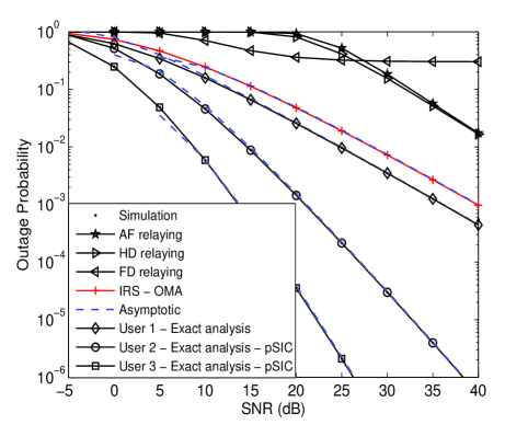
Fig. 2 plots the outage probability of three users versus SNR for a simulation setting with , , , , , and BPCU. The theoretical analysis curves of outage probability for users with pSIC are plotted according to (1). It is obvious that the Monte Carlo simulation outage probability curves excellently agree with analytical results across the entire average SNR range. The asymptotic outage probability converges to the analytical expressions given in (4), which proves the effectiveness of our theoretical derivation. As can be seen from the figure that the outage performance of the nearest user () is higher than that of the distant users ( and ). This is due to the fact that the nearby user attains the higher diversity order, which verifies the insights in Remark 2. The exact and asymptotic outage probability cures of IRS-OMA are plotted according to the analytical results in (12) and (19), respectively. One can observe that the outage behaviors of IRS-NOMA with pSIC are superior than that of IRS-OMA (12), variable gain AF relaying [46], FD relaying [47, Eq. (7)] with loop self-interference i.e., dB and HD relaying [47, Eq. (8)]. The reasons are that: 1) IRS-NOMA can realize much better user fairness than IRS-OMA for multiple users; 2) FD DF relay suffers from loop interference due to signal leakage and needs the advanced loop interference cancellation technologies, which will lead to the higher cost; and 3) IRS-NOMA operates in FD mode provides the more spectrum efficient than HD DF relaying.
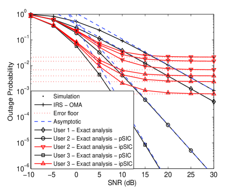
Fig. 3 plots the outage probability of three users versus SNR for a simulation setting with , , , , , , and BPCU. The exact and approximate analyses curves of outage probability for users with ipSIC are plotted by (1) and (3), respectively. The exact and asymptotic outage probability curves of IRS-OMA are plotted by (12) and (20), respectively. The simulation results matches closely with the theoretical analysis. The important observation is that the outage probability of distant users with ipSIC converges to an error floor in the high SNR regime and thus obtain a zero diversity order. The reason is that there is the residual interference from ipSIC for IRS-NOMA. This phenomenon is also confirmed by the conclusions in Remark 1. Additionally, it is worth noting that the farthest user () does not carry out the SIC operation, since it has the worst channel conditions. Compared to the benchmark of IRS-OMA, we observe that IRS-NOMA with ipSIC is also capable of achieving the lower outage behaviors. Certainly, with the value of residual interference increasing, the achieved outage probability of IRS-NOMA converges to the worst error floors. As a result, it is important to consider the influence of ipSIC on the network performance for IRS-NOMA in the practical scenario.
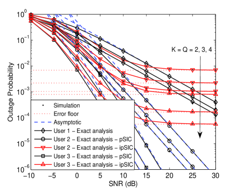
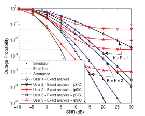
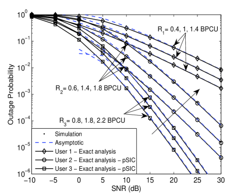
Fig. 4 plots the outage probability versus SNR for a simulation system with different reflecting elements of IRS and dB. One can observe that the setting of the reflecting elements for IRS-NOMA is significant to provide the network performance. With increasing the number of reflecting elements , the lower outage probabilities are attained for multiple users. These behaviors are caused by the fact that the application of IRS to NOMA networks provides a new degree of freedom to enhance the wireless link performance. This phenomenon is also certificate the completion of Remark 2, where both the number of reflecting elements and channel ordering determine the slope of outage probability for IRS-NOMA. Another observation is that all outage probability curves of each user have the same slopes, which manifests that the diversity orders of users are the same. This appearance demonstrates the insight we derived from the analytical results given by (4).
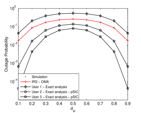
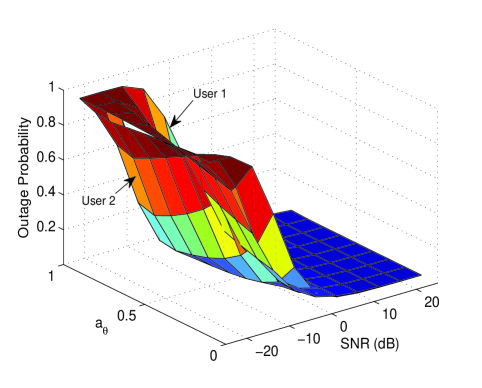
Fig. 5 plots the outage probability versus SNR for a simulation setting with , , , , BPCU and dB. The approximated outage probability curves of users are plotted corresponding to (4), which match precisely with the simulation results. As can be observed from the figure that as the number of reflecting elements increases, the outage probability of users is becoming much smaller. The main reason behind this is that IRS-NOMA with 1-bit coding provides much more diversity orders given by Remark 2. It is worth mentioning that the outage probability curves of each user has a different diversity order, which confirms the analytical result derived in (4). Fig. 6 plots the outage probability versus SNR with the different target rate for , and . One can observe that adjusting the target rate of users largely affect the outage performance. With the values of target rate increasing, the outage behaviors of users for IRS-NOMA networks are becoming much worse, which is in line with the conventional NOMA networks [7].
Fig. 7 plots the outage probability as a function of the normalized distance between the BS and users, with , , , BPCU, BPCU. We can observe that when the IRS is deployed closely to BS, the outage performance of non-orthogonal users is becoming much better. This phenomenon can be explained that the IRS can receive the clear LoS signals from the BS for the purpose of maximizing its received signal power. As the IRS departs from BS, the LoS deteriorates and outage probability of users increases seriously. When the IRS is in the middle of the BS and users, the worst outage behaviors of users are attained in IRS-NOMA networks. This is due to the fact that the IRS is neither closed to the BS nor to users. After this point, the performance begins to improve again. This is because that the IRS is close to NOMA users and enhance the reflecting signals received by users. Such an outage behavior can be useful to establish an optimal deployment of IRS in NOMA networks. As can be seen that the deployment scenarios of IRS should take into account some practical constraints.
To illustrate the impact of power allocation coefficients on system performance, Fig. 8 plots the outage probability versus SNR and , with with , , , and BPCU, where is dynamic power allocation coefficients and the value range is zero to one i.e., . We assume that there are a pair of users () in IRS-NOMA networks and the power coefficients of user 1 and user 2 have the relationships of and . The analytical curves of outage probability are plotted according to (1). It is observed from the figure that with the value of increasing, the outage behavior of user 1 deteriorates gradually, while the performance of user 2 first becomes better and then tends to worse. The reason for this phenomenon is that user 1 suffers more interference from user 2 when it detects its own information. At this time, user 2 needs to detect the signal of user 1 before detecting its own signal. Hence it is critical to design the power allocation coefficients for balancing the performance of two users.
VI-B Ergodic Rate
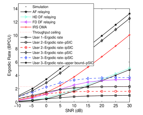
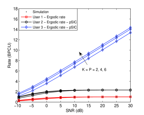
Fig. 9 plots the ergodic rates versus SNR, with , and . The red and blue dotted curves denote the ergodic rates of the -th user and -th user with ipSIC for IRS-NOMA networks, which are plotted according to (IV) and (23), respectively. The exact curves of ergodic rate for the -th and -th user with pSIC are plotted based on (2) and (3), respectively. One can observe that the ergdic rates of the -th and -th user with ipSIC are inferior to that of the -th and -th user with pSIC. The main reason is that the ergdic rates suffer from the residual interference of ipSIC and tends to constant values at high SNRs. Another observation is that the ergodic rates of distant users for IRS-NOMA outperform that of AF relaying and FD/HD relaying in the low SNR regime, which are consistent to FD/HD NOMA systems[9, 10]. As the SNR value increases, the ergodic rate of distant users converges to a throughput ceiling, which is also confirmed in Remark 4. This is due to the fact that the distant user will suffer from the interference from the nearby users’ signals when it decodes their own signals. Another observation is that the ergodic rate of nearest user is much greater than that of non-orthogonal users, IRS-OMA (6), AF relaying and FD/HD relaying. The origin for this behavior is that it is closest to the IRS and has the best channel conditions. In addition, Fig. 10 plots the ergodic rates versus SNR with different reflecting elements. As can be observed from this figure that with the increasing reflecting elements of IRS, the ergodic performance of the nearest user with pSIC is enhanced and has the same slopes, which confirms the insights in Remark 5. The distant users’ performance has no obvious variety due to the effects of interference signals. We conclude that IRS-NOMA cannot circumvent the problem of slope for the distant users.
VI-C Energy Efficiency
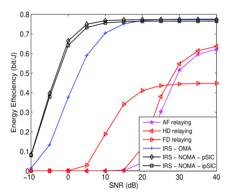
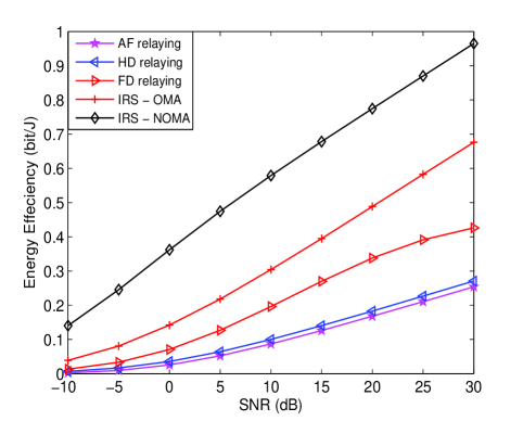
Fig. 11 plots the energy efficiency for IRS-NOMA networks in the delay-limited transmission mode, with , , , , = 5 dBW, = 2 dBW, = 10 dBm and = 10 dBm. The energy efficiency curve of IRS-NOMA networks with ipSIC/pSIC is plotted according to (34). It can be observed that the energy efficiency of IRS-NOMA outperforms that of IRS-OMA and converge to the same value in the high SNR regime. This is due to the fact that the setting of sum target rate for non-orthogonal users is equal to the orthogonal user in delay-limited transmission mode. Another observation is that the energy efficiencies of IRS-NOMA and IRS-OMA are superior to that of AF relaying and FD/HD DF relaying. The main reason is that the IRS-assisted wireless communications are capable of improving the energy efficiency compared to these conventional cooperative communications. As a further advance, Fig. 12 plots the energy efficiency for IRS-NOMA in delay-tolerant transmission mode, with , , , , = 10 dBW, = 4 dBW, = 10 dBm and = 10 dBm. The energy efficiency curve of IRS-NOMA networks with pSIC is plotted according to (34). We can observe that the energy efficiency of IRS-NOMA is much larger than that of IRS-OMA, AF relaying, FD/HD DF relaying. This is due to that IRS-NOMA with pSIC is able to achieve the larger system throughput relative to these benchmarks.
VII Conclusion
In this paper, an IRS has been invoked in downlink NOMA networks for enhancing the performance of multiple users, where 1-bit coding scheme is taken into account. More specifically, we have derived the exact expressions of outage probability and ergodic rate for users with ipSIC/pSIC in IRS-assisted NOMA networks. Based on the approximated analyses, the diversity order of the -th user is related to the number of reflecting elements and channel ordering. With increasing the number of reflecting elements, the outage probability of users with ipSIC/pSIC for IRS-NOMA networks decreases. Due to the interference from the nearby users’ signals, a of high SNR slope for ergodic rate is obtained by the distant users. Simulation results have shown that the outage behaviors of IRS-NOMA are superior to that of IRS-OMA, AF relaying and FD/HD DF relaying. The nearest user has a larger ergodic rate than orthogonal user and distant users. Finally, the throughput and energy efficiency of IRS-NOMA were discussed both in delay-limited and delay-tolerant transmission modes. The application of IRS to NOMA provided a new degree of freedom to enhance the wireless link performance.
Appendix A: Proof of Theorem 1
The proof starts by assuming , and then
| (A.1) |
Hence the outage probability of the -th user with ipSIC need to further calculate . Applying the complementary set and some algebraic manipulations, it can be calculated as follows:
| (A.2) |
where , , , with and . Based on the previous assumption, the cascade channel gains from the BS to IRS and then to users with 1-bit coding scheme are also sorted as . As a further advance, we focus our attention the CDF in the following part.
Denoting , the CDF of the cascade channel gain has a fixed relationship with the unsorted channel gain [39, 7], which can be expressed as
| (A.3) |
where denotes the CDF of unsorted cascade channel gain. After some arithmetical manipulations, we can further express , where and . Based on [48, Eq. (7)], the PDF of the cascade channel gain from the BS to IRS and then to users is given by
| (A.4) |
where denotes the PDF of unsorted cascade channel gain. Furthermore, we perform integral processing on the above formula and express the corresponding CDF as
| (A.5) |
where .
Based on (A.5), using and [42, Eq. (6.561.8)], can be calculated as follows:
| (A.6) |
Upon substituting (Appendix A: Proof of Theorem 1) into (Appendix A: Proof of Theorem 1), the CDF of the cascade channel gain can be given by
| (A.7) |
where .
Combining (Appendix A: Proof of Theorem 1) and (Appendix A: Proof of Theorem 1), the probability can be further expressed as follows:
| (A.8) |
where . Assuming , and using Gauss-Laguerre integration [49, Eq. (25.4.45)], the probability can be given by
| (A.9) |
where , is the weight of the Gauss-Laguerre integration. is the -th zero of Laguerre polynomial and the corresponding the -th weight is given by .
Upon substituting (Appendix A: Proof of Theorem 1) into (Appendix A: Proof of Theorem 1), we can obtain (1). The proof is completed.
Appendix B: Proof of Theorem 2
Upon substituting into (IV), the ergodic rate of the -th user with pSIC for IRS-NOMA networks can be written as
| (B.1) |
Let and the CDF can be expressed as
| (B.2) |
where . Upon substituting (Appendix A: Proof of Theorem 1) into (B.2) and using Binomial theorem, the CDF is given by
| (B.3) |
where .
For IRS-NOMA with 1-bit coding scheme, and are independent and identically distribution for . As a consequence, the CDF can be given by
| (B.4) |
Upon substituting (Appendix B: Proof of Theorem 2) into (Appendix B: Proof of Theorem 2), the CDF can be expressed as follows:
| (B.5) |
By further applying the Gauss-Chebyshev quadrature [50] on the above equation, we can obtain (2). The proof is completed.
Appendix C: Proof of Theorem 3
Upon substituting into (23), the ergodic rate of the -th user with pSIC for IRS-NOMA networks can be written as
| (C.1) |
Denoting , by the virtue of Order Statistic theory and (Appendix A: Proof of Theorem 1), the CDF of the -th user is given by
| (C.2) |
Similar to the procedure in (Appendix B: Proof of Theorem 2), we randomly select a column from to maximize . Hence the CDF can be given by
| (C.3) |
Applying the Binomial theorem in (Appendix C: Proof of Theorem 3), the CDF can be further rewritten as follow:
| (C.4) |
By substituting (Appendix C: Proof of Theorem 3) and after some manipulates, we can obtain (3). The proof is completed.
References
- [1] Y. Liu, Z. Qin, M. Elkashlan, Z. Ding, A. Nallanathan, and L. Hanzo, “Non-orthogonal multiple access for 5G and beyond,” Proceedings of the IEEE, vol. 105, no. 12, pp. 2347–2381, Dec. 2017.
- [2] W. Saad, M. Bennis, and M. Chen, “A vision of 6G wireless systems: Applications, trends, technologies, and open research problems,” IEEE Network, pp. 1–9, Oct. 2019.
- [3] Z. Zhang, Y. Xiao, Z. Ma, M. Xiao, Z. Ding, X. Lei, G. K. Karagiannidis, and P. Fan, “6G wireless networks: Vision, requirements, architecture, and key technologies,” IEEE Veh. Technol. Mag., vol. 14, no. 3, pp. 28–41, Sep. 2019.
- [4] D. Tse and P. Viswanath, Fundamentals of wireless communication, Cambridge University Press, Cambridge, UK, 2005.
- [5] Z. Ding, Y. Liu, J. Choi, Q. Sun, M. Elkashlan, C. L. I, and H. V. Poor, “Application of non-orthogonal multiple access in LTE and 5G networks,” IEEE Commun. Mag., vol. 55, no. 2, pp. 185–191, Feb. 2017.
- [6] Z. Ding, Z. Yang, P. Fan, and H. V. Poor, “On the performance of non-orthogonal multiple access in 5G systems with randomly deployed users,” IEEE Signal Process. Lett., vol. 21, no. 12, pp. 1501–1505, Dec. 2014.
- [7] X. Yue, Z. Qin, Y. Liu, S. Kang, and Y. Chen, “A unified framework for non-orthogonal multiple access,” IEEE Trans. Commun., vol. 66, no. 11, pp. 5346–5359, Nov. 2018.
- [8] Z. Ding, M. Peng, and H. V. Poor, “Cooperative non-orthogonal multiple access in 5G systems,” IEEE Commun. Lett., vol. 19, no. 8, pp. 1462–1465, Aug. 2015.
- [9] C. Zhong and Z. Zhang, “Non-orthogonal multiple access with cooperative full-duplex relaying,” IEEE Commun. Lett., vol. 20, no. 12, pp. 2478–2481, Dec. 2016.
- [10] X. Yue, Y. Liu, S. Kang, A. Nallanathan, and Z. Ding, “Exploiting full/half-duplex user relaying in NOMA systems,” IEEE Trans. Commun., vol. 66, no. 2, pp. 560–575, Feb. 2018.
- [11] Y. Liu, Z. Ding, M. Elkashlan, and H. V. Poor, “Cooperative non-orthogonal multiple access with simultaneous wireless information and power transfer,” IEEE J. Sel. Areas Commun., vol. 34, no. 4, pp. 938–953, Apr. 2016.
- [12] X. Liang, Y. Wu, D. W. K. Ng, Y. Zuo, S. Jin, and H. Zhu, “Outage performance for cooperative NOMA transmission with an AF relay,” IEEE Commun. Lett., vol. 21, no. 11, pp. 2428–2431, Nov. 2017.
- [13] J. Men, J. Ge, and C. Zhang, “Performance analysis of non-orthogonal multiple access for relaying networks over nakagami- fading channels,” IEEE Trans. Veh. Technol., vol. 66, no. 2, pp. 1200–1208, Feb. 2017.
- [14] X. Yue, Y. Liu, S. Kang, and A. Nallanathan, “Performance analysis of NOMA with fixed gain relaying over Nakagami- fading channels,” IEEE Access, vol. 5, pp. 5445–5454, Mar. 2017.
- [15] Q. Y. Liau, C. Y. Leow, and Z. Ding, “Amplify-and-forward virtual full-duplex relaying-based cooperative NOMA,” IEEE Wireless Communications Letters, vol. 7, no. 3, pp. 464–467, Jun. 2018.
- [16] X. Yue, Y. Liu, Y. Yao, X. Li, R. Liu, and A. Nallanathan, “Secure communications in a unified non-orthogonal multiple access framework,” IEEE Trans. Wireless Commun., vol. 19, no. 3, pp. 2163–2178, Mar. 2020.
- [17] Y. Liu, Z. Qin, Y. Cai, Y. Gao, G. Y. Li, and A. Nallanathan, “UAV communications based on non-orthogonal multiple access,” IEEE Wireless Commun., vol. 26, no. 1, pp. 52–57, Feb. 2019.
- [18] X. Yan, H. Xiao, C. Wang, K. An, A. T. Chronopoulos, and G. Zheng, “Performance analysis of NOMA-based land mobile satellite networks,” IEEE Access, vol. 6, pp. 31 327–31 339, Jun. 2018.
- [19] J. Zhao, “A survey of intelligent reflecting surfaces (IRSs): Towards 6G wireless communication networks with massive MIMO 2.0,” 2019. [Online]. Available: http://arxiv.org/abs/1907.04789v2.
- [20] T. Cui, M. Qi, X. Wan, J. Zhao, and Q. Cheng, “Coding metamaterials, digital metamaterials and programmable metamaterials,” Light: Science & Applications,, vol. 3, no. 10, Oct. 2014.
- [21] Q. Wu and R. Zhang, “Towards smart and reconfigurable environment: Intelligent reflecting surface aided wireless network,” IEEE Commun. Mag., vol. 58, no. 1, pp. 106–112, Jan. 2020.
- [22] Y. Liu, X. Liu, X. Mu, T. Hou, J. Xu, Z. Qin, M. D. Renzo, and N. Al-Dhahir, “Reconfigurable intelligent surfaces: Principles and opportunities,” 2020. [Online]. Available: https://arxiv.org/abs/2007.03435v1.
- [23] E. Bjornson, O. Ozdogan, and E. G. Larsson, “Intelligent reflecting surface vs. decode-and-forward: How large surfaces are needed to beat relaying?” 2019. [Online]. Available: https://arxiv.org/abs/1906.03949.
- [24] M. D. Renzo, K. Ntontin, J. Song, F. H. Danufane, X. Qian, F. Lazarakis, J. de Rosny, D.-T. Phan-Huy, O. Simeone, R. Zhang, M. Debbah, G. Lerosey, M. Fink, S. Tretyakov, and S. Shamai, “Reconfigurable intelligent surfaces vs. relaying: Differences, similarities, and performance comparison,” IEEE Open J. Commun. Soc., to appear in 2020.
- [25] E. Basar, M. Di Renzo, J. de Rosny, M. Debbah, M. Alouini, and R. Zhang, “Wireless communications through reconfigurable intelligent surfaces,” IEEE Access, vol. 7, pp. 116 753–116 773, Aug. 2019.
- [26] M. Cui, G. Zhang, and R. Zhang, “Secure wireless communication via intelligent reflecting surface,” IEEE Wireless Commun. Lett., vol. 8, no. 5, pp. 1410–1414, Oct. 2019.
- [27] C. Huang, A. Zappone, G. C. Alexandropoulos, M. Debbah, and C. Yuen, “Reconfigurable intelligent surfaces for energy efficiency in wireless communication,” IEEE Trans. Wireless Commun., vol. 18, no. 8, pp. 4157–4170, Aug. 2019.
- [28] J. Liu, K. Xiong, Y. Lu, D. W. K. Ng, Z. Zhong, and Z. Han, “Energy efficiency in secure IRS-aided SWIPT,” IEEE Wireless Commun. Lett., to appear in 2020.
- [29] N. S. Perovi, M. D. Renzo, and M. F. Flanagan, “Channel capacity optimization using reconfigurable intelligent surfaces in indoor mmwave environments,” in IEEE Proc. of International Commun. Conf. (ICC), Dublin, IRL, Jun. 2020, pp. 1–7.
- [30] B. Zheng, Q. Wu, and R. Zhang, “Intelligent reflecting surface-assisted multiple access with user pairing: NOMA or OMA?” IEEE Commun. Lett., vol. 24, no. 4, pp. 753–757, Apr. 2020.
- [31] M. Fu, Y. Zhou, and Y. Shi, “Intelligent reflecting surface for downlink non-orthogonal multiple access networks,” in IEEE Proc. of Global Commun. Conf. (GLOBECOM), Waikoloa, USA, Dec. 2019, pp. 1–6.
- [32] G. Yang, X. Xu, and Y.-C. Liang, “Intelligent reflecting surface assisted non-orthogonal multiple access,” in IEEE Proc. of International Wireless Commun. Networking Conf. (WCNC), Seoul, Kr, May 2020, pp. 1–6.
- [33] J. Zuo, Y. Liu, Z. Qin, and N. Al-Dhahir, “Resource allocation in intelligent reflecting surface assisted NOMA systems,” IEEE Trans. Commun., to appear in 2020.
- [34] X. Mu, Y. Liu, L. Guo, J. Lin, and N. Al-Dhahir, “Exploting intelligent reflecting surface in multi-antenna aided NOMA systems,” 2019. [Online]. Available: https://arxiv.org/abs/1910.13636v1.
- [35] Z. Ding and H. V. Poor, “A simple design of IRS-NOMA transmission,” IEEE Commun. Lett., vol. 24, no. 5, pp. 1119–1123, May 2020.
- [36] Z. Ding, R. Schober, and H. V. Poor, “On the impact of phase shifting designs on IRS-NOMA,” IEEE Wireless Commun. Lett., to appear in 2020.
- [37] T. Hou, Y. Liu, Z. Song, X. Su, Y. Chen, and L. Hanzo, “Reconfigurable intelligent reflecting surface aided NOMA networks,” 2019. [Online]. Available: https://arxiv.org/abs/1912.10044v1.
- [38] L. Yang and Y. Yuan, “Secrecy outage probability analysis for RIS-assisted NOMA systems,” 2020. [Online]. Available: https://arxiv.org/abs/2007.15902.
- [39] H. A. David and H. N. Nagaraja, Order Statistics, 3rd ed. New York: John Wiley, 2003.
- [40] M. A. Kishk and M.-S. Alouini, “Exploiting randomly-located blockages for large-scale deployment of intelligent surface,” 2020. [Online]. Available: https://arxiv.org/abs/2001.10766.
- [41] M. Nemati, J. Park, and J. Choi, “RIS-assisted coverage enhancement in millimeter-wave cellular networks,” 2020. [Online]. Available: https://arxiv.org/abs/2007.08196v1.
- [42] I. S. Gradshteyn and I. M. Ryzhik, Table of Integrals, Series and Products, 6th ed. New York, NY, USA: Academic Press, 2000.
- [43] A. A. Nasir, X. Zhou, S. Durrani, and R. A. Kennedy, “Relaying protocols for wireless energy harvesting and information processing,” IEEE Trans. Wireless Commun., vol. 12, no. 7, pp. 3622–3636, Jul. 2013.
- [44] R. Mendez-Rial, C. Rusu, N. Gonzalez-Prelcic, A. Alkhateeb, and R. W. Heath, “Hybrid MIMO architectures for millimeter wave communications: Phase shifters or switches?” IEEE Access, vol. 4, pp. 247–267, Jan. 2016.
- [45] L. N. Ribeiro, M. R. S. Schwarz, and A. L. F. de Almeida, “Energy efficiency of mmwave massive MIMO precoding with low-resolution DACs,” IEEE J. Sel. Topics Signal Process., vol. 12, no. 2, pp. 298–312, May 2018.
- [46] J. N. Laneman, D. N. C. Tse, and G. W. Wornell, “Cooperative diversity in wireless networks: Efficient protocols and outage behavior,” IEEE Trans. Inf. Theory, vol. 50, no. 12, pp. 3062–3080, Dec. 2004.
- [47] T. Kwon, S. Lim, S. Choi, and D. Hong, “Optimal duplex mode for DF relay in terms of the outage probability,” IEEE Trans. Veh. Technol., vol. 59, no. 7, pp. 3628–3634, Sep. 2010.
- [48] H. Liu, H. Ding, L. Xiang, J. Yuana, and L. Zhenga, “Outage and ber performance analysis of cascade channel in relay networks,” in in Proc. the 9th International Conference on Future Networks and Communications, India, Feb. 2014, pp. 1–8.
- [49] M. Abramowitz and I. Stegun, Handbook of Mathematical Functions with Formulas, Graphs, and Mathematical Tables, New York, NY, USA: Dover, 1972.
- [50] E. Hildebrand, Introduction to numerical analysis, New York, NY, USA: Dover, 1987.