Radiative Heat Transfer
in
Free-Standing Silicon Nitride Membranes
Abstract
Free-standing silicon nitride (SiN) mechanical resonators are of central interests in applications such as temperature and mass sensing, and for fundamental optomechanical research. Understanding thermal coupling between a membrane resonator and its environment is required for predicting thermal noise, frequency noise, as well as sensors responses to temperature changes. In this work, we provide closed-form derivations of intrinsic thermal coupling quantities in free-standing thin films–namely total thermal conductance with the surroundings, thermal response time, and the relative contribution of thermal radiation. Our model is valid for any free-standing thin film anchored on all sides, although we particularly emphasize the specific case of SiN for which spectral emissivity is thoroughly investigated as a function of thickness and temperature. We find that radiative heat exchanges can play a non-negligible role, and even dominate thermal coupling for membranes of sizes commonly employed in optomechanics experiments. We experimentally confirm the validity of our model by measuring radiative thermal coupling between a SiN mechanical resonator and a ceramic heater in high vacuum.
1 Introduction
Thin-film silicon nitride (SiN) membranes are heavily used as mechanical and optical resonators in both fundamental opto-mechanical studies [1, 2, 3] and many state-of-the-art sensing technologies, including ultra-sensitive mass sensing [4], gas detection [5], nanoparticulate mass detection [6], thermal radiation sensing [7, 8] and pressure sensing [9]. Some of these works involve cooling [1, 3], while in other cases, the temperature dependence of membrane stress is used as a sensing mechanism [8, 7], or an active technique for controlling resonator frequency [10].
Despite, the strong influence of temperature in SiN membranes, there is still no closed-form expression describing thermal coupling with their environment, as well as their characteristic thermal response time (). As such, our goal is to provide expression for ; for the heat conduction between the membrane and the environment (, in ); and for the fraction () of this conduction that occurs via thermal radiation. We provide these expressions for the specific case SiN films of square and circular shape in vacuum (i.e., in the absence of convection heat transfer).
Analytical expression for thermal coupling of SiN membranes are notably needed for understanding their fundamental noise mechanisms. Values of and are central in the calculation of noise processes such as temperature fluctuation noise and temperature-induced frequency fluctuation [11, 12, 13].
Likewise, in the context of nanomechanical radiation sensors [7], understanding the ratio of heat transfer occurring via radiation () is key for determining ultimate sensor detectivity and noise equivalent power [14]. The fundamental performance limit of a thermal-based radiation sensor is notably reached when thermal coupling between the sensor and the surroundings is dominated by radiation (i.e., ) [7, 10, 15].
Efforts have been devoted to investigating the thermal properties [16, 17, 18] of SiN membranes such as thermal conductivity, heat capacity, diffusivity and thermal expansion coefficient. Emissivity of metal coating on SiN membranes have also been investigated in the context of electron microscopy [19]. Meanwhile, others have provided finite element simulation [20] of temperature profiles SiN membranes. Nevertheless, to the best of our knowledge, there is still no rigorous closed-form analytical expression describing heat transfer in such membranes.
2 Heat transfer in free-standing thin films
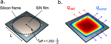
In order to calculate thermal coupling between a freestanding film and its environment, we consider volumetric heat generation () occurring uniformly within the membrane. From a heat transfer standpoint, such internal generation is mathematically analogous to uniform absorption of radiation from an external radiation source (e.g., in the context of radiation sensors). As a result of this internal generation, membrane temperature () rises relative to ambient (), and heat leaves the membrane by conduction to the silicon frame (, in W), and re-emission of radiation to the environment (, in W), as schematized in Fig. 1(b). For example, an extreme case in which the membrane would be perfectly coupled to its environment via radiation would yield , and , where and is the membrane volume. We neglect the contribution of convective heat transfer, an assumption representative of a system in vacuum as in most optomechanics and thermal radiation sensing experiments. In steady state, heat flux out of the system must equal heat generation inside the system, yielding the general heat equation:
| (1) |
where is the membrane conductivity, and is the position-dependent membrane temperature. In Eq. (1), is the radiative exchange, per unit volume, between membrane and the environment at ; is it given by:
| (2) |
Where is the membrane thickness, is Stefan-Boltzmann constant, and is the total hemispherical emissivity of SiN. The factor 2 accounts for emission on both faces of the membrane. We consider Dirichlet boundary conditions, setting the temperature of the SiN membrane edges to be the same as the ambient temperature ().
The non-linear nature of radiative heat exchange () prevents direct derivation of a closed-form solution of the heat equation. We consequently linearize Eq. (2) by considering a small temperature difference between the membrane and the environment, yielding:
| (3) |
Due to the minute scale thickness of the SiN film, we consider uniform temperature along the direction normal to the surface, thus reducing Eq. (1) to a two-dimensional problem.
For a circular membrane of radius , the solution to the linearized heat equation in cylindrical coordinates is conveniently simple:
| (4) |
where
| (5) |
and is the order modified Bessel function of the first kind. From this temperature profile, we calculate heat transfer by conduction at the boundaries, using Fourier law of conduction:
| (6) |
which yields:
| (7) |
From Eq. (7), we can finally calculate the fraction of heat that leaves the membrane radiation ():
| (8) |
In Eq. (8), we note that the right-hand side depends only on intrinsic membrane properties (i.e., independent of ). As such, solving for yields the properties required for a membrane to be thermally coupled to its environment more strongly via radiation than via solid-state conduction.
From the temperature profile of the membrane [see Eq. (4)], we can also express the thermal time constant of the membrane (, in s) and its overall thermal conductance with the environment (, ), both of which are of particular importance for use in sensors [14], and for predicting noise profiles in micro resonators [11, 12, 13]. Note that includes heat transfer both by conduction in the supporting frame () and by radiation (). We obtain and by evaluating the average temperature () of the membrane [i.e., by integrating Eq. (4)] and using:
| (9) | |||
| (10) |
where and are respectively the specific heat capacity and the material density. We note that, when heat transfer becomes entirely dominated by radiation (i.e. for large areas), Bessel terms become negligible and both expressions simplify to radius-independent quantities:
| (11) | |||
| (12) |
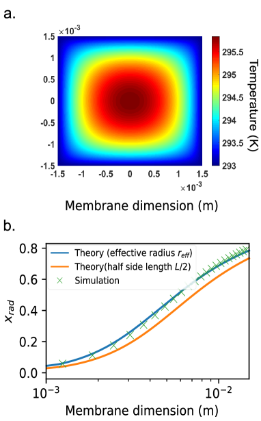
For a square membrane, a geometry much more frequently encountered in practice, an analytical solution to the linearized heat equation also exists, but comprises an infinite amount of Fourier terms in order to respect the boundary conditions ( at the membrane edges). Rather than using this complex solution, we numerically solve for the temperature profile of a square membrane using finite element analysis. From this solution (see supplemental Fig. S1), we determine that the radiative thermal coupling ratio () of a square membrane of side length matches that of a circular membrane if we consider an effective radius:
| (13) |
Logically, this effective radius falls between half of a square membrane side length (), and half of its diagonal (), as shown schematically in Fig. 1(a). By replacing Eq. (13) in Eq. (8), the fraction of heat transfer occurring by radiation in a square membrane () is given by:
| (14) |
The total thermal conductance of a square membrane is subsequently:
| (15) |
while is now given by:
| (16) |
Eq. (16) yields an aberrant when , but this result occurs for , in which case our assumption of a 2-D problem (i.e., ) does not hold.
3 Emissivity of SiN films
From Eq. (8) to Eq. (16), it is obvious that the total hemispherical emissivity () is a key parameter governing radiative heat transfer in free-standing membranes. We calculate for the specific case of SiN using Kirchhoff law–i.e., directional spectral emissivity is equal to absorption:
| (17) |
We calculate using conventional optical multi-layer calculation [21] with the complex permittivity of SiN taken from [22]. and denote the optical power reflection and transmission coefficients, respectively. We find that these coefficients depend non-negligibly on the angle, such that we integrate the emissivity according to Lambert’s cosine law to obtain [23]:
| (18) |
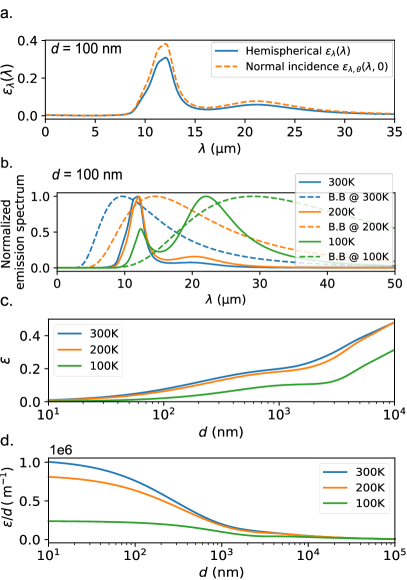
which is plotted in Fig. 2(a) for the specific example of a 100 nm thick membrane. In comparison, the normal directional spectral emissivity is roughly higher than the integrated value . In other words, emission and absorption are slightly stronger at normal incidence. This may be beneficial for radiation sensing applications [14] where a sensor should be more strongly coupled at normal incidence (i.e. pointing at the object to be detected). We finally obtain the total hemispherical emissivity by weighting with the blackbody emission spectrum at temperature :
| (19) |
where . For concision, we use the notation in this work. This weighting is shown, for various membrane temperatures, in Fig. 2(b) while as a function of thicknesses, is presented in Fig. 2(c). We find that both the emission distribution [Fig. 1(b)] and [Fig. 1(c)] weakly depend on temperature unless cryogenic membrane temperatures (e.g., 100 K) are considered.We willingly omit calculations at very low temperatures () as this would presumably require a different model for material properties of SiN. We also note that the hemispherical emissivity for thin films is a strong function of thickness. This emphasizes that the common assumption of [7] for SiN appears appropriate only for bulk SiN materials and not for thin films.
We note that thicker films lead to higher emissivity [see Fig. 2(c)]–however as shown in Eq. (5), the relevant quantity for estimating the contribution of radiation to the total heat transfer is the ratio . This is plotted in Fig. 2(d), from which we conclude that, for a given surface area, thinner membranes are more efficiently coupled via radiation. The thickness dependence is the strongest in the 100 nm–1 range, while the relation reaches a relative plateau for thickness commonly employed in opto-mechanics experiments () [24].

Having calculated the ratio, we can determine the critical membrane length for which heat transfer is dominated by radiation (i.e., ). Using the closed-form relation developed in Eq. (14), we plot as a function of in Fig. 3(a). The value for SiN, for given and , is given in Fig. 3(b). We note that Fig. 3(a) is a universal relation for any freestanding thin film membrane anchored on all sides, while Fig. 3(b) accounts for the specific case of SiN. In Fig. 3(a), we find that thermal coupling of free-standing thin films is radiation dominated for . From this, we finally derive a simple expression for the threshold of a radiation-coupled membrane:
| (20) |
for which the ratio can be obtained graphically from Fig. 2(d), in the specific case of SiN. We note that this equation is the same for a circular membrane, using in lieu of for a square membrane.
4 Experimental results
We verify our model by conducting experiments using a commercially available ( mm side length, 200 nm thickness) low stress SiN membrane. We correlate the membrane temperature to its mechanical resonance frequency () using the relation given in [10]. The change in temperature of the membrane () is measured by comparing its instantaneous resonance () with its initial room-temperature resonance ():
| (21) |
where SiN Young’s modulus is , the thermal expansion coefficient is [18] and the tensile stress is . We consider a uncertainty for this relation given the variability of material constants and on the membrane dimensions [see error bars in Fig. 4(d)]. The experiment is conducted in high vacuum () to eliminate convection heat transfer and viscous damping by air.
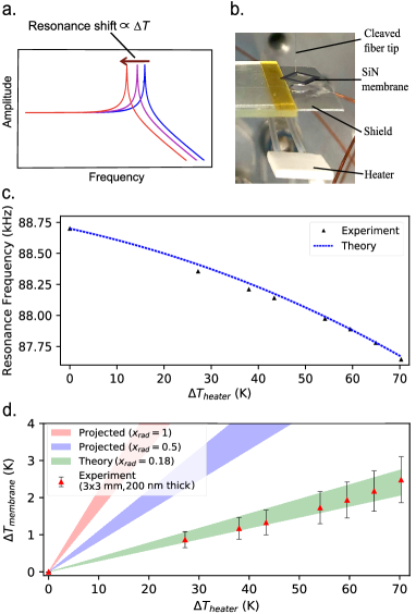
We vary the temperature of the SiN membrane by exposing it to a rough-surfaced aluminum oxide heater [see Fig 4.(b)] placed within a short distance (5 mm) from the membrane. We infer the heater temperature by correlating it to its electrical resistance using a temperature coefficient of resistance of . We measure this value in a separate experiment by placing the heater on a hot plate and by measuring its resistance as a function of temperature. Due to the variability in documented value for the total hemispherical emissivity of rough-surfaced aluminum oxide [23], we assume an upper bound value of and a lower bound of 0.6. A reflective aluminum shield is placed between the membrane and the heater to prevent the silicon frame of the membrane from heating up upon absorption of radiation. A piezoelectric actuator is attached to the same glass slide as the membrane to excite its mechanical resonance. Membrane displacement is measured using an optical interferometer setup [25]. The instantaneous resonance () of the SiN membrane shifts by over 1 KHz when subject to a 70 K increment in heater temperature, as presented in Fig. 4(c).
By neglecting photons having more than one interaction with the heater and membrane (due to the relatively small size of the membrane, the diffusive surface of the heater, and its high emissivity/absorptivity) the temperature of the membrane is correlated to the heater temperature simply by:
| (22) |
where, is the geometrical view factor [23]. The detailed thermal equivalent circuit from which Eq. (22) derived is given in supplementary Fig. S2. From Eq. (22), correlating the membrane temperature with the heater temperature allows measurement of and validation of our model. This is presented in Fig. 4(d), where the experimental points fall within the theoretically expected values from Eq. (14). For illustrative purpose, we also plot the projected values for a membrane that would be on the threshold () or completely radiation-dominated (), for the same geometrical view factor ().
5 conclusion
We expect that our work will be interest for achieving high performance radiation sensors exploiting the high temperature sensitivity of SiN mechanical resonance [10]. In such sensors, one would ideally want to achieve to reach the highest possible detectivity [14]. Our work shows that achieving such value is feasible using realistic membrane dimensions. We readily achieve using commercially available SiN membranes of non-optimized dimensions. We also expect that the provided closed-form expressions for and will be of great use for predicting frequency noise in high Q-factor SiN [11, 12, 13]. Given the high temperature sensitivity of resonance frequency in SiN resonators, we expect temperature fluctuation noise–which is directly linked to and [13]–to have a non-negligible contribution to frequency noise. Finally, we expect that outlining the non-negligible contribution of radiation heat transfer may be useful in experiments involving cooling of SiN membranes. As a striking example, a membrane with could be more efficiently cooled by a cold object facing it, than by direct contact cooling of its supporting silicon frame.
References
- Wilson et al. [2009] D. J. Wilson, C. A. Regal, S. B. Papp, and H. J. Kimble. Cavity optomechanics with stoichiometric sin films. Phys. Rev. Lett., 103:207204, Nov 2009. doi:10.1103/PhysRevLett.103.207204.
- Regal and Lehnert [2011] C. A. Regal and K. W. Lehnert. From cavity electromechanics to cavity optomechanics. In Journal of Physics: Conference Series, 2011. doi:10.1088/1742-6596/264/1/012025.
- Chakram et al. [2014] S. Chakram, Y. S. Patil, L. Chang, and M. Vengalattore. Dissipation in ultrahigh quality factor sin membrane resonators. Phys. Rev. Lett., 112:127201, Mar 2014. doi:10.1103/PhysRevLett.112.127201.
- Hanay et al. [2012] M. S. Hanay, S. Kelber, A. K. Naik, D. Chi, S. Hentz, E. C. Bullard, E. Colinet, L. Duraffourg, and M. L. Roukes. Single-protein nanomechanical mass spectrometry in real time. Nature Nanotechnology, 7(9):602–608, 2012. ISSN 17483395. doi:10.1038/nnano.2012.119.
- Brucoli et al. [2014-02-24] Giovanni Brucoli, Patrick Bouchon, Riad Haïdar, Mondher Besbes, Henri Benisty, and Jean-Jacques Greffet. High efficiency quasi-monochromatic infrared emitter. Applied Physics Letters, 104(8), 2014-02-24. ISSN 0003-6951.
- Larsen et al. [2013] Tom Larsen, Silvan Schmid, Luis G. Villanueva, and Anja Boisen. Photothermal analysis of individual nanoparticulate samples using micromechanical resonators. ACS Nano, 7(7):6188–6193, 2013. ISSN 19360851. doi:10.1021/nn402057f.
- Zhang et al. [2013] X. C. Zhang, E. B. Myers, J. E. Sader, and M. L. Roukes. Nanomechanical torsional resonators for frequency-shift infrared thermal sensing. Nano Letters, 13(4):1528–1534, 2013. ISSN 15306984. doi:10.1021/nl304687p.
- Zhang et al. [2019] C Zhang, M Giroux, T A Nour, and R St-Gelais. Thermal radiation sensing using high mechanical Q-factor silicon nitride membranes. In 2019 IEEE SENSORS, pages 1–4, oct 2019. doi:10.1109/SENSORS43011.2019.8956551.
- Zhu et al. [2013] Shou En Zhu, Murali Krishna Ghatkesar, Chao Zhang, and G. C.A.M. Janssen. Graphene based piezoresistive pressure sensor. Applied Physics Letters, 102(16):2011–2014, 2013. ISSN 00036951. doi:10.1063/1.4802799.
- St-Gelais et al. [2019] Raphael St-Gelais, Simon Bernard, Christoph Reinhardt, and Jack C. Sankey. Swept-Frequency Drumhead Optomechanical Resonators. ACS Photonics, 2019. ISSN 23304022. doi:10.1021/acsphotonics.8b01519.
- Sansa et al. [2016] Marc Sansa, Eric Sage, Elizabeth C. Bullard, Marc Gély, Thomas Alava, Eric Colinet, Akshay K. Naik, Luis Guillermo Villanueva, Laurent Duraffourg, Michael L. Roukes, Guillaume Jourdan, and Sébastien Hentz. Frequency fluctuations in silicon nanoresonators. Nature Nanotechnology, 2016. ISSN 17483395. doi:10.1038/nnano.2016.19.
- Fong et al. [2012] King Y. Fong, Wolfram H. P. Pernice, and Hong X. Tang. Frequency and phase noise of ultrahigh silicon nitride nanomechanical resonators. Phys. Rev. B, 85:161410, Apr 2012. doi:10.1103/PhysRevB.85.161410.
- Cleland and Roukes [2002] A. N. Cleland and M. L. Roukes. Noise processes in nanomechanical resonators. Journal of Applied Physics, 2002. ISSN 00218979. doi:10.1063/1.1499745.
- Rogalski [2003] Antoni Rogalski. Infrared detectors: Status and trends. Progress in Quantum Electronics, 27(2-3):59–210, 2003. ISSN 00796727. doi:10.1016/S0079-6727(02)00024-1.
- Blaikie et al. [2019] Andrew Blaikie, David Miller, and Benjamín J. Alemán. A fast and sensitive room-temperature graphene nanomechanical bolometer. Nature Communications, 2019. ISSN 20411723. doi:10.1038/s41467-019-12562-2.
- Sikora et al. [2012] A. Sikora, H. Ftouni, J. Richard, C. Hébert, D. Eon, F. Omnès, and O. Bourgeois. Highly sensitive thermal conductivity measurements of suspended membranes (SiN and diamond) using a 3-Völklein method, 2012. ISSN 00346748.
- Zhang and Grigoropoulos [1995] Xiang Zhang and Costas P. Grigoropoulos. Thermal conductivity and diffusivity of free-standing silicon nitride thin films. Review of Scientific Instruments, 66(2):1115–1120, 1995. ISSN 00346748. doi:10.1063/1.1145989.
- Tien and Lin [2012] Chuen-Lin Tien and Tsai-Wei Lin. Thermal expansion coefficient and thermomechanical properties of SiN x thin films prepared by plasma-enhanced chemical vapor deposition . Applied Optics, 2012. ISSN 1559-128X. doi:10.1364/ao.51.007229.
- Van Zwol et al. [2015] P. J. Van Zwol, D. F. Vles, W. P. Voorthuijzen, M. Péter, H. Vermeulen, W. J. Van Der Zande, J. M. Sturm, R. W.E. Van De Kruijs, and F. Bijkerk. Emissivity of freestanding membranes with thin metal coatings. Journal of Applied Physics, 2015. ISSN 10897550. doi:10.1063/1.4936851.
- Revaz et al. [2003] B. Revaz, B. L. Zink, D. O’Neil, L. Hull, and F. Hellman. Numerical simulation of the heat transfer in amorphous silicon nitride membrane-based microcalorimeters. Review of Scientific Instruments, 2003. ISSN 00346748. doi:10.1063/1.1605498.
- Edalatpour and Francoeur [2013-03] Sheila Edalatpour and Mathieu Francoeur. Size effect on the emissivity of thin films. Journal of Quantitative Spectroscopy and Radiative Transfer, 118:75,85, 2013-03. ISSN 0022-4073.
- Cataldo et al. [2012] Giuseppe Cataldo, James A Beall, Hsiao-mei Cho, Brendan Mcandrew, Michael D Niemack, and Edward J Wollack. Infrared dielectric properties of low-stress silicon nitride. 37(20):4200–4202, 2012.
- L.Bergman and S.Lavine [2017] Theodore L.Bergman and Adrienne S.Lavine. Fundamentals of Heat and Mass Transfer. Wiley, 8th editio edition, 2017. ISBN 9781119330103.
- Zwickl et al. [2008] B. M. Zwickl, W. E. Shanks, A. M. Jayich, C. Yang, A. C.Bleszynski Jayich, J. D. Thompson, and J. G.E. Harris. High quality mechanical and optical properties of commercial silicon nitride membranes. Applied Physics Letters, 92(10):2006–2009, 2008. ISSN 00036951. doi:10.1063/1.2884191.
- Rugar et al. [1989] D. Rugar, H. J. Mamin, and P. Guethner. Improved fiber-optic interferometer for atomic force microscopy. Applied Physics Letters, 1989. ISSN 00036951. doi:10.1063/1.101987.
Supplementary Information
S.1 Numerical simulation
The 2-D steady-state temperature profile of the squre-sized SiN membrane is simulated using MATLAB PDE solver, such that the closed-form analytical results can be compared with the numerical simulation. We first define the computational geometry to be a square which has the same side length (3 mm) as the sample SiN membrane. We then specify the coefficients for the PDE model by rearranging the heat equation as:
| (S1) |
where is the Stefan-Boltzmann constant, is the total hemisphereical emissivity of the 200 nm () SiN membrane which is calculate to be 0.11, is the ambient temperature (293 K), is the conductivity of the SiN membane which is found to be 12 . Note that is the heating power being absorbed by the SiN membrane per unit volume. Here we arbitrarily set . The simulated temperature profile is shown in Fig. S1(a).
With the numerical simulation, we can obtain the fraction of heat that leaves the membrane by radiation () using the simulated temperature profile. By plotting this result and the analytical results for many side lengths values, we find that the correction ratio between the effective radius and half of the side length to be 1.252 which is presented in Eq. (13)
S.2 Thermal equivalent circuit
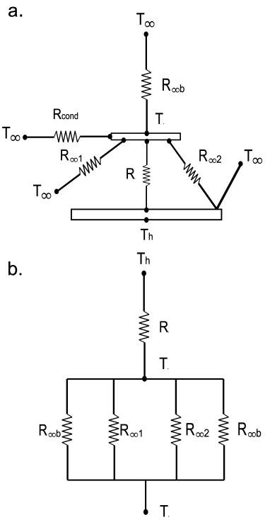
The analogy of the electric circuit is useful to understand the heat transfer of the SiN membrane with its environment. Here we neglect multiple heat exchanges between the SiN membrane and the heater by only considering single photon interaction. In other words, photons leaving the membrane and reflected by the surface of the heater will be directed to the environment, which results in resistance in Fig. S2. This assumption is based on the fact that the surface of the heater is highly diffusive, and the surface area of the membrane is substantially smaller than the area of the heater. Hence, photons emitted by the membrane and then hit the surface of the heater have minimal chance of being reflected back to the membrane.
By rearranging the thermal circuit schematic in Fig. S2(a), we reach the simplified thermal circuit shown in Fig. S2(b) for which the resistances are expressed as:
| (S2) |
| (S3) |
| (S4) |
| (S5) |
| (S6) |
Here, is the total hemispherical emissivity of the SiN membrane, is the total hemispherical emissivity of the ceramic heater, is the geometrical view factor from the membrane to the heater and is surface area of the SiN membrane. By following the thermal circuit in Fig. S2(b), we obtain Eq. (22) in the main text.