Towards Optimal Kinetic Energy Harvesting for the Batteryless IoT
Abstract
Traditional Internet of Things (IoT) sensors rely on batteries that need to be replaced or recharged frequently which impedes their pervasive deployment. A promising alternative is to employ energy harvesters that convert the environmental energy into electrical energy. Kinetic Energy Harvesting (KEH) converts the ambient motion/vibration energy into electrical energy to power the IoT sensor nodes. However, most previous works employ KEH without dynamically tracking the optimal operating point of the transducer for maximum power output. In this paper, we systematically analyze the relation between the operating point of the transducer and the corresponding energy yield. To this end, we explore the voltage-current characteristics of the KEH transducer to find its Maximum Power Point (MPP). We show how this operating point can be approximated in a practical energy harvesting circuit. We design two hardware circuit prototypes to evaluate the performance of the proposed mechanism and analyze the harvested energy using a precise load shaker under a wide set of controlled conditions typically found in human-centric applications. We analyze the dynamic current-voltage characteristics and specify the relation between the MPP sampling rate and harvesting efficiency which outlines the need for dynamic MPP tracking. The results show that the proposed energy harvesting mechanism outperforms the conventional method in terms of generated power and offers at least one order of magnitude higher power than the latter.
Index Terms:
IoT, Wearable, Batteryless, Kinetic, Energy harvester, Power, Vibrations, Maximum power point, FrequencyI Introduction
The IoT is identified as one of the major technologies impacting various applications including healthcare, agriculture, transportation, smart homes and more, by enabling many sensors to collect and exchange data for smarter and effective decisions [1]. However, IoT sensors rely mostly on batteries for their operation. Batteries are bulky, expensive, hazardous and have limited charge/discharge cycles which impedes the pervasive deployment of IoT [2]. As a way of tackling these challenges, energy harvesting from ambient sources such as solar, kinetic, thermal and RF waves has been used to convert the environmental energy into electrical energy to power batteryless IoT sensors without human intervention [1]. With recent technological advancements, energy harvesting can enable perpetual operation of IoT sensor nodes which is the key for realising a truly pervasive, batteryless IoT.
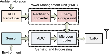
Kinetic Energy Harvesting is an attractive option to realise a truly pervasive batteryless IoT by converting the ambient vibration, motion and mechanical energy into electrical energy. A Power Management Unit (PMU) is used to manage the harvested energy [3] to power a load (or a node) as depicted in Fig. 1. The harvested energy is stored in an energy storage unit (i.e., a capacitor/battery) which is used to power a sensor node. The harvested energy is consumed by various hardware components within the sensor node including the sensor module, Analog-to-Digital Converter (ADC), microcontroller and transceiver to sample the physical attribute as well as its transmission to the destination/server. Depending upon the application, the harvested energy can be large enough to power the sensors without the need of any external depletable energy source leading to Energy Neutral Operation (ENO).
Piezoelectric transducers are often used to power the sensors in human-centric IoT applications including the human activity [4] and transport modes. In order to harvest maximum energy from the transducer, it must operate at its MPP. Although, MPP tracking has been used in KEH [4] to increase harvested energy, it has not been systematically compared with the conventional design in terms of harvested energy. In addition, the dynamic tracking of MPP of the KEH transducer is still unexplored. Furthermore, there is no detailed study to compare the performance of the energy harvesting circuits with and without MPP tracking of the transducer under a wide set of conditions typically found in human-centric applications.
In this paper, we explore the operation of a KEH transducer at the MPP using a DC-DC boost converter at different frequency and amplitude levels for human-centric IoT applications. A DC-DC boost converter consumes some amount of energy during its operation which may impact the overall harvested energy compared to a converter-less design. In this document, we refer to DC-DC boost converter as DC-DC converter and converter interchangeably. In order to do a fair comparison, we perform the experiments in a controlled environment using a stable load shaker whose vibration frequency and amplitude can be adjusted manually. We study the relation between harvesting efficiency and MPP sampling rate which outlines the need for dynamic MPP tracking. The results show that exploiting the MPP of the transducer, the proposed mechanism harvests, on average, at least one order of magnitude higher power, than the conventional converter-less design, depending on the vibration amplitude.
The main contributions of the this paper are given as:
-
•
We analyze the dynamic electrical characteristics of a KEH transducer and explore its MPP.
-
•
We design two hardware circuit prototypes; converter-less and converter-based, to explore the impact of MPP tracking using a DC-DC converter.
-
•
We perform an experiment in a controlled environment using a stable load shaker and find that the proposed converter-based circuit harvests, on average, one order of magnitude higher power than the conventional converter-less design due to its operation at MPP.
The remainder of the paper is organized as follows. Section II discusses the previous energy harvesting based IoT devices and Section III presents the proposed energy harvesting design. The prototyping and experimental setup is described in Section IV. Section V explores the MPP of the KEH transducer and provides the results. Finally, Section VI concludes the paper and gives the future direction.
II Related Work
In batteryless IoT nodes, energy harvesters are employed to provide unceasing energy for their operation. Zhao et al. [5] design a KEH based shoe to harvest energy from the human motion. Their prototype harvests of power while walking at a frequency of about . Their work shows the feasibility of using energy harvesters to power the batteryless wearable devices. Authors in [6] design a KEH based wearable device to be placed on the wrist to harvest energy from human motion. As human arms offer lower vibrations compared to legs, they harvest of energy during small human movements. Ryokai et al. [7] design a KEH based wearable device for children to harvest energy from their movements. The harvested energy from the wrist based wearable devices is used to turn on the Light Emitting Diode (LED) to inspire the children to learn about energy and its transformation from one form to another. Olivo et al. [8] propose a fast start-up mechanism for wearable sensors using KEH. They employ a boosting circuit to step-up the harvesting voltage to power the wearable nodes. Authors in [9] employ KEH to harvest energy from human movements to power the wearable devices. They design backpack-based and insole-like harvesters which generate large enough energy to power the on-body nodes. Xiang et al. [10] use KEH transducer to harvest energy from the air flow of indoor Heating, Ventilation, and Air Conditioning (HVAC) system. The harvested energy is used to transmit information about the air flow speed to the server. Kuang et al. [4] employ KEH to harvest energy from the knee-joint energy harvester during human motion. They design KEH hardware which operates the transducer at its MPP to harvest higher energy to power the body sensor.
Some of the previous works [10, 6, 8] employ DC-DC boost converters in the KEH circuits to harvest higher energy for IoT nodes. However, they do not explore the MPP of the KEH transducer which is challenging due to the rapid changes in its output power. The authors in [4] do not employ dynamic tracking of MPP under a wide set of conditions typically found in human-centric applications. Furthermore, to the best of our knowledge, there is no detailed study that compares the performance of employing the MPP of the KEH transducer with the conventional energy harvesting mechanisms for miniaturized IoT sensor nodes. This papers presents the operation of a KEH transducer at MPP to harvest higher energy and compares its performance with the conventional converter-less energy harvesting circuit under a wide set of conditions typically found in human-centric applications.
III Kinetic Energy Harvesting
There are three mechanisms for converting the kinetic energy to electrical energy: piezoelectric, electromagnetic and electrostatic [11]. Piezoelectric is the most favourable choice for wearable applications due to its simplicity and compatibility with micro-electro-mechanical systems. We discuss the functionality of the piezoelectric transducer and the proposed energy harvesting circuits in the following subsections in detail.
III-A Piezoelectric transducer
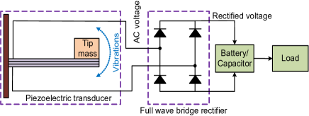
A piezoelectric transducer is used to convert the ambient vibration and kinetic energy into electrical energy as shown in Fig. 2. Under mechanical stress, it generates an electric field with alternating polarity [11]. The harvesting AC voltage is rectified using a bridge rectifier and is used to charge a capacitor. Then, the energy stored in the capacitor is used to power a load as shown in Fig. 2. The harvested energy from the piezoelectric transducer depends upon many factors including the resonance frequency, amplitude and frequency of vibration. The resonance frequency is an intrinsic property of the piezoelectric transducer, depending on its geometry, manufacturing parameters and material properties which can not be changed later. Using a tip mass, the resonance frequency of the harvester can be tuned according to specific application requirements. However, it requires human intervention each time while there is a change in vibration characteristic. The amount of energy harvested from a piezoelectric transducer depends upon the dynamic vibration characteristics which in turn depends upon the application in which the transducer is being deployed. These dynamics also change the optimum operating point of the transducer in terms of mechanical tuning as well as electrical loading. Therefore, there is a need to devise a method that harvest maximum energy under given vibration characteristics without human intervention (i.e., without replacing piezoelectric transducers and/or tuning the resonance frequency). Accordingly, we explore the impact of these uncontrollable parameters (vibration amplitude and frequency) on the harvested energy using different energy harvesting hardware designs employing the MPP of the transducer, as described in the following subsections and find the best design under a given nature of vibration characteristics.
III-B Energy harvesting circuits using KEH transducer
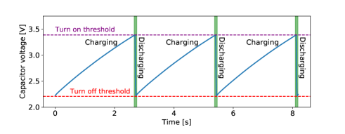
In batteryless IoT devices, the load is turned on when the capacitor voltage reaches to a turn-on threshold and is turned off when the capacitor voltage drops to a turn-off threshold as shown in Fig. 3. The stored energy in the capacitor is calculated as:
| (1) |
where, is the capacitance and is the capacitor voltage. Fig. 3 shows the typical intermittent execution pattern of a batteryless device. The energy consumed by the load is given as:
| (2) |
As Fig. 3 depicts, the frequency of executing the load depends on the rate of charging of the capacitor. There are two main design options for charging the capacitor which are described in detail below.
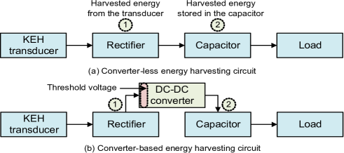
Converter-less design. This is a conventional circuit for harvesting energy and powering a load. In a converter-less design, the capacitor is placed in parallel to the rectifier. Therefore, the voltage across the transducer is given as:
| (3) |
where, is the capacitor voltage and is the voltage drop across the corresponding diode in the full wave rectifier. If the open circuit voltage is higher than the voltage on the capacitor, is approximately constant (one diode drop, typically 111Using schottky diodes) and thus, the voltage across the transducer equals the capacitor voltage plus two diode drops. This may result in low energy yield. For example, if the capacitor voltage is and the input vibration is low, then the open circuit voltage of the transducer may be less than . In this case, no current can flow and thus energy that could have potentially been harvested is wasted. The dependence between capacitor voltage and transducer voltage has important implications for the harvested energy.
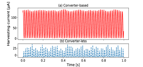
Converter-based design. In a converter-based design, a DC-DC boost-converter [10] is placed between the rectifier and the capacitor. This allows to optimize the operating point (i.e., harvesting voltage) of the transducer independent of the voltage on the capacitor. For example, the converter can be configured to regulate the transducer voltage at its input to by dynamically controlling the current flow from the transducer. This allows to extract energy from the transducer for charging the capacitor even under very low motion or vibrations. It can also be used to fix the transducer voltage to its MPP, extracting higher energy from the transducer. The decoupling of the transducer from the capacitor and load has a significant impact on the current flow from the transducer. Fig. 4 shows the harvesting current from converter-less and converter based designs. In the converter-based design, the capacitor is decoupled from the transducer using DC-DC converter with fixed input voltage threshold according to MPP of the transducer which allows four times higher current flow than the converter-less design.
IV Prototyping and Experimental Setup
For our study, we design two KEH hardware prototypes for collecting data from two types of energy harvesting circuits: converter-less (Fig. 5a) and converter-based (Fig. 5b). We use an S230-J1FR-1808XB two-layered piezoelectric bending transducer from MIDÉ technology222https://www.mide.com/ with a block tip mass of 0.5% which has a resonance frequency of . All signals are sampled at a frequency of using a 12-bit ADC. Both designs in Fig. 5 use a capacitor to temporarily store the harvested energy and an intermittently powered load333In this experiment, we set = and = consisting of two LEDs, mimicking the behaviour of a batteryless device. The converter-based design (in Fig. 5b) uses an ultra low power TI BQ25504 DC-DC boost converter to step up the transducer voltage. The input threshold voltage of the converter is linearly swept from to in steps. The prototypes are designed as dataloggers with a focus on enabling accurate measurements of energy rather than on optimizing the harvesting efficiency.
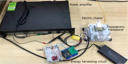
We use a 1-lb load shaker444https://controlledvibration.com/product-item/1lb-load-shaker/ along with a power amplifier00footnotemark: 0, DSi 1000, to excite the transducer at varying amplitude and frequency of vibration. An arbitrary waveform generator555https://www.rigolna.com/products/waveform-generators/dg4000/, RIGOL DG4162, is used to provide a single tone sinusoidal signal to the power amplifier which drives the load shaker. The experimental setup for measuring the harvested power in converter-less and converter-based designs is shown in Fig. 6. In this experiment, we fixed the signal from the waveform generator to a sine wave with varying amplitude levels (referred as vibration amplitudes in the rest of the paper) from to peak-to-peak and frequency from to . These values of vibration amplitude and frequency are selected by considering the real vibration characteristics from various transport modes [12]. A piezoelectric transducer is mounted on the load shaker, and the converter-less and converter-based energy harvesting circuits are employed consecutively to sample the generated voltage and current signals.
V Results and Discussion
In this section, we present the harvested power from the converter-less and converter-based designs, and study the benefit of operating the KEH transducer at its MPP.
V-A MPP of the KEH transducer
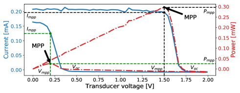
In the converter-based energy harvesting circuit, we can choose the input voltage threshold of the DC-DC converter in order to operate the transducer at its MPP. As shown in Fig. 7, the MPP of the piezoelectric transducer is defined by its current-voltage characteristics. We explore the IV characteristics of the piezoelectric transducer to find its MPP using an uncontrolled bridge rectifier and a KEITHLEY 2602B source meter666https://www.tek.com/keithley-source-measure-units/smu-2600b-series-sourcemeter. We rapidly sweep through the range of voltage and record the corresponding current at a sampling frequency of . In order to analyze the MPP of the piezoelectric transducer, we plot two IV curves in Fig. 7. It shows that the current from the transducer decreases with the increase in the output voltage, reaching to zero at the open circuit voltage . Fig. 7 also plots the output power over the transducer voltage. It depicts that the MPP lies near 50-80% of the open circuit voltage.
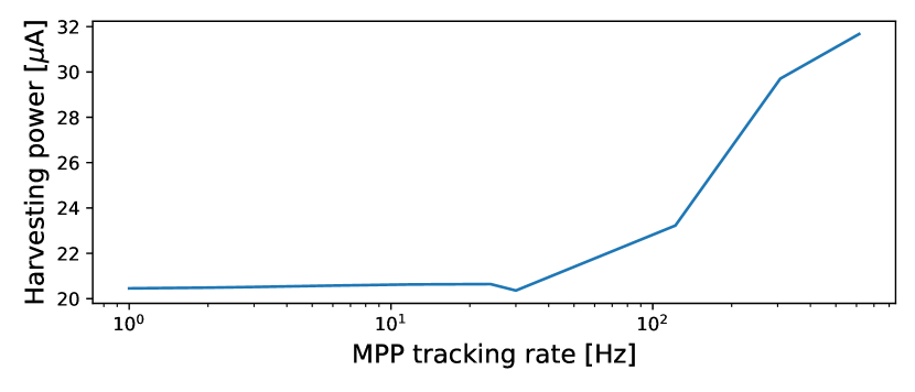
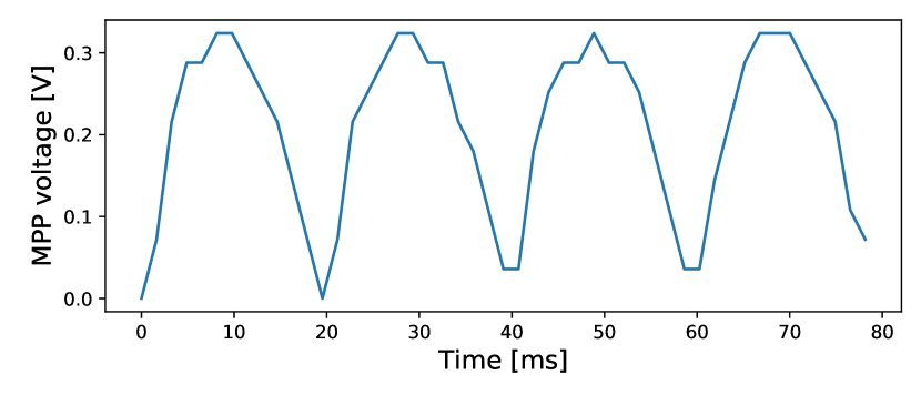
It also shows the corresponding current and power at MPP. From the figure, it is clear that with the change in IV curve, the MPP also changes according to the open circuit voltage. Fig. 8 shows the dynamic pattern of MPP voltage with time. The MPP varies with the oscillations of the transducer due to the change in the output voltage. We analyse the effect of slow MPP tracking by calculating the power when undersampling the MPP, i.e., we select the harvesting voltage at the MPP and then keep harvesting at that voltage for seconds, where is the tracking frequency. Fig. 9 shows that harvested power significantly increases with increased MPP tracking speed. This means, that in order to extract maximum power from the transducer, we would need to dynamically track its MPP. Practical MPP tracking circuits usually disconnect the harvester and sample the open circuit voltage in order to estimate the MPP. This incurs significant losses while the harvester is disconnected. These losses linearly increase with increasing MPP sampling rate. Furthermore, off-the-shelf DC-DC converters, like the one used in our prototype offer only a fixed MPP sampling interval of , which is far too low to track the MPP of a KEH transducer. Therefore, for this study, we only consider static MPP tracking, where the MPP is estimated once for the given vibration characteristics and then kept constant.
Recalling, the intermittent execution pattern from Fig. 3, we note that the capacitor voltage is always in the range of turn-on and turn-off thresholds under normal operating conditions. From Eq. 3, we know that the rectified transducer operating voltage equals the capacitor voltage. Thus, without a DC-DC converter, the transducer is operated at voltages between and in our prototype. However, Fig. 12 shows that the MPP voltage is often significantly lower. With the converter-less design, the transducer is operated far from the MPP, which can significantly reduce the output power as shown in figure 7. In contrast, by using a DC-DC converter, we can optimize the operating point of the transducer and as a result achieve greatly improved energy yield even with static MPP tracking.
V-B Harvested power stored in the capacitor
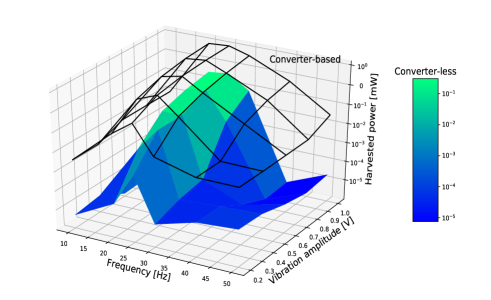
We employ converter-less and converter-based designs to harvest power at varying levels of input vibrations. Fig. 10 shows the harvested power calculated from the stored energy in the capacitor at varying frequency and amplitude levels of input vibrations. For the converter-based design, the harvested power is at the MPP. Fig. 10 shows that both designs harvest highest power at the resonance frequency due to the higher output power from the transducer. However, the converter-based circuit harvests higher power than the converter-less design at all frequency and amplitude levels of input vibrations. It offers about 26.5 to 409 times (on average, 112 times) higher power than the converter-less design while operating at the resonance frequency under varying vibration amplitudes. The reason for higher harvested power in converter-based design is the operation of the piezoelectric transducer at its MPP.
V-C Impact of threshold voltage of DC-DC converter on the harvested power
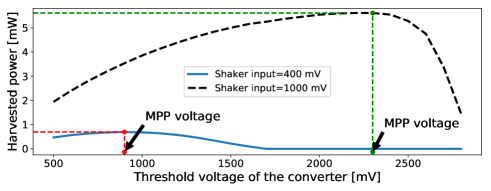
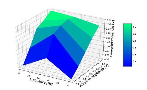
We calculate the harvested power stored in the capacitor in the converter-based design using different voltage thresholds of the DC-DC converter and plot the results in Fig. 11. It shows that at a specific voltage threshold of the DC-DC converter, higher power is harvested which corresponds to the MPP of the transducer. Fig. 11 also shows that increasing the vibration amplitude (from to ) generates a higher transducer voltage, which in turn shifts the dynamic MPP towards a higher voltage as discussed in Section V-A. The MPP voltage depends on the underlying vibration characteristics. Fig. 12 plots the voltage threshold of DC-DC converter at MPP with varying vibration frequency and amplitude levels. It shows that the threshold voltage of the converter at which maximum power is attained (i.e., MPP), increases with the escalation in the vibration amplitude. For a given vibration level, the MPP threshold is highest at the resonance frequency of the piezoelectric transducer due to the higher transducer voltage at this specific frequency.
V-D Power consumption of DC-DC converter
In the converter-less design, the rectifier is the only significant source of losses. The actual charging of the capacitor is almost lossless. In the converter-based design instead, the converter itself causes significant losses, affecting the overall efficiency of the system. Even if the converter is not operational, for example, when there is no vibration exciting the transducer, it still consumes a so-called quiescent current. The ultra low power DC-DC boost converter777http://www.ti.com/lit/ds/symlink/bq25504.pdf TI BQ25504 that we use in our prototype, consumes a maximum of of power at a typical capacitor voltage of . This is in the same range as the sleeping current of state of the art microcontrollers. While the converter is actively charging the capacitor, it consumes additional power that, together with various switching losses reduces the efficiency, i.e. the ratio of output power to input power The datasheet shows that the efficiency of the converter generally increases with the increase in input voltage and input current from the transducer. For example, at typical harvesting conditions of and , the converter reaches at an efficiency of more than .
Despite these losses, we find that the gain from operating the transducer at the MPP by far outweighs the losses incurred by the DC-DC converter.
VI Conclusion and Future Work
KEH converts the ambient vibration, motion and mechanical energy into electrical energy to power the IoT sensor nodes. The conventional energy harvesting circuit employs a rectifier which rectifies the harvesting voltage to charge a capacitor which is further used to drive a load/node. However, this configuration lacks the operation of the transducer at its MPP which results in lower harvested energy. In this paper, we explore the MPP of the KEH transducer for optimal energy harvesting. We fix the voltage from the transducer to its MPP resulting in higher harvested energy. We experimentally analyze the dynamic IV characteristics and based on that specify the relation between the MPP sampling rate and harvesting efficiency, outlining the need for real, dynamic MPP tracking which is not currently available on commercial off-the-shelf hardware. We study the performance of converter-less and converter-based energy harvesting circuits in a controlled environment using a stable load shaker. The results show that the converter-based circuit harvests, on average, at least one order of magnitude higher power, than the converter-less design, due to its operation at MPP, under a wide set of conditions typically found in human-centric applications.
In future, we intend to study the performance of converter-less and converter-based circuits in a real world scenario using real-time MPP tracking. In addition, an energy efficient circuit can be designed that solely operates on the harvested energy resulting in ENO of the batteryless IoT sensor node.
References
- [1] J. Lin, et al., “A survey on internet of things: Architecture, enabling technologies, security and privacy, and applications,” IEEE Internet Things J., vol. 4, no. 5, pp. 1125–1142, 2017.
- [2] J. Hester, et al., “The future of sensing is batteryless, intermittent, and awesome,” in Proc. 15th ACM SenSys, 2017, p. 21.
- [3] J. J. Estrada-López, et al., “Multiple input energy harvesting systems for autonomous iot end-nodes,” J. Low Power Electron. Appl., vol. 8, no. 1, p. 6, 2018.
- [4] Y. Kuang, et al., “Energy harvesting during human walking to power a wireless sensor node,” Sens. Actuator A-Phys., vol. 254, pp. 69–77, 2017.
- [5] J. Zhao, et al., “A shoe-embedded piezoelectric energy harvester for wearable sensors,” Sensors, vol. 14, no. 7, pp. 12 497–12 510, 2014.
- [6] M. Magno, et al., “Kinetic energy harvesting: Toward autonomous wearable sensing for internet of things,” in Proc. 2016 IEEE SPEEDAM, 2016, pp. 248–254.
- [7] K. Ryokai, et al., “Energybugs: energy harvesting wearables for children,” in Proc. 2014 ACM CHI, 2014, pp. 1039–1048.
- [8] J. Olivo, et al., “A kinetic energy harvester with fast start-up for wearable body-monitoring sensors,” in Proc. 4th PervasiveHealth. IEEE, 2010, pp. 1–7.
- [9] L. Xie, et al., “Human motion: sustainable power for wearable electronics,” IEEE Pervasive Comput., vol. 13, no. 4, pp. 42–49, 2014.
- [10] T. Xiang, et al., “Powering indoor sensing with airflows: a trinity of energy harvesting, synchronous duty-cycling, and sensing,” in Proc. 11th ACM SenSys, 2013, p. 16.
- [11] S. Khalifa, et al., “Harke: Human activity recognition from kinetic energy harvesting data in wearable devices,” IEEE Trans. Mobile Comput., vol. 17, no. 6, pp. 1353–1368, 2017.
- [12] S. Hemminki, et al., “Accelerometer-based transportation mode detection on smartphones,” in Proc. 11th ACM SenSys, 2013, p. 13.