Joint Interleaver and Modulation Design For Multi-User SWIPT-NOMA
Abstract
Radio frequency (RF) signals can be relied upon for conventional wireless information transfer (WIT) and for challenging wireless power transfer (WPT), which triggers the significant research interest in the topic of simultaneous wireless information and power transfer (SWIPT). By further exploiting the advanced non-orthogonal-multiple-access (NOMA) technique, we are capable of improving the spectrum efficiency of the resource-limited SWIPT system. In our SWIPT system, a hybrid access point (H-AP) superimposes the modulated symbols destined to multiple WIT users by exploiting the power-domain NOMA, while WPT users are capable of harvesting the energy carried by the superposition symbols. In order to maximise the amount of energy transferred to the WPT users, we propose a joint design of the energy interleaver and the constellation rotation based modulator in the symbol-block level by constructively superimposing the symbols destined to the WIT users in the power domain. Furthermore, a transmit power allocation scheme is proposed to guarantee the symbol-error-ratio (SER) of all the WIT users. By considering the sensitivity of practical energy harvesters, the simulation results demonstrate that our scheme is capable of substantially increasing the WPT performance without any remarkable degradation of the WIT performance.
Index Terms:
RF based WPT, energy interleaving, constellation rotation based modulation, NOMA, SWIPTI Introduction
I-A Background
In the upcoming era of 5G and Internet of Things (IoT), massive machine-type communications are enabled by the deployment of low-power IoT devices, which triggers more difficulties on the spectrum efficiency [1], energy efficiency [2], or security [3]. In order to accommodate the explosive growth of the machine-type tele-traffic, non-orthogonal-multiple-access (NOMA) [4][5] emerges as a critical technique for substantially increasing the spectrum efficiency. The NOMA aided transmitter differentiates the symbols destined to the different users by allocating various transmit power to these symbols superimposed in the same time-frequency resource block. The successive interference cancellation (SIC) technique [6] is adopted by the users for recovering their requested symbols from the superposition one. For a specific user, the symbols requested by the other users are sequentially demodulated and removed from the superposition symbol until its own requested one is successfully recovered. In order to further increase the spectrum efficiency, the multiple-input-multiple-output (MIMO) technique [7] is combined with the NOMA by providing additional multiplexing gain in the spatial domain. By allowing the downlink and uplink transmissions in the same time-frequency resource block, the full-duplex technique may further double the spectrum efficiency of the NOMA [8], if the self-interference can be appropriately mitigated.
Furthermore, in order to alleviate their energy shortage, radio frequency (RF) signal based wireless power transfer (WPT) can be relied upon for remotely charging these battery-powered IoT devices [9]. However, coordinating the conventional wireless information transfer (WIT) and the wireless power transfer (WPT) in the same RF band is a challenging task, which thus stimulates substantial research interest in the topic of simultaneous wireless information and power transfer (SWIPT) [10]. In a SWIPT systems, the simultaneous reception of both the information and energy is realised by invoking a signal splitter at the receiver, which is capable of splitting the received RF signal either in the time-domain [11], or in the power-domain [12] or in the spatial domain [13]. Furthermore, by exploiting the broadcast nature of the wireless channels, the transmitter is capable of simultaneously transferring RF signals to both the WIT users and the WPT users [14]. Specifically, the WIT users recover the requested information from the received RF signals, while the WPT users harvest energy from their received RF signals.
I-B Related Works
Recently, some pioneering works have studied the multi-user SWIPT-NOMA system. For instance, Zheng et al. [15] considered a NOMA aided cooperative NOMA network, where a transmitter communicates with a pair of receivers via a single wireless powered relay. The optimal power allocation scheme was found for maximising the total downlink throughput. Moreover, Liu et al. [16] proposed a novel protocol for the NOMA aided cooperative network, in which the users close to the transmitters operate as the wireless powered relays for the sake of forwarding the information to the distant users. Xu et al. [17] proposed a joint design of the transmit beamforming and receive power splitting in a similar NOMA aided cooperative network, which aims for maximising the achievable throughput of the so-called ‘strong users’, while ensuring the minimum throughput requirements of other ‘weak users’. Diamantoulakis et al. [18] studied a wireless-powered communication network, in which the uplink transmission of multi-user is supported by the NOMA. Furthermore, Alsaba et al. [19] studied a NOMA aided cooperative system, where the ‘strong user’ adopts the full-duplex technique for simultaneously receiving the RF signal from the base station and for relaying information to the ‘weak user’. The sum-throughput was then maximised by invoking a two-step convex optimisation method. Mohammadali et al. [20] studied a NOMA-SWIPT system having a battery powered access point and a pair of energy harvesting users. They investigated the information-energy trade-off, while studying the performance of cognitive radio aided NOMA. In their scheme, the transmit power is allocated to the user having poor channel conditions in order to satisfy certain quality of service (QoS) requirements. Dai et al. [21] investigated a millimeter-wave aided NOMA-SWIPT system on order to further enhance the spectrum efficiency. Moreover, Wei et al. [22] proposed a transceiver design in a cooperative NOMA-SWIPT system, where the power allocation, the power splitting (PS) ratio and the receiver filter, as well as the transmit beamformer are jointly optimized for maximising the SWIPT performance.
In the most of the existing works concerning the NOMA aided WIT and SWIPT systems, the WIT performance was always characterised by the classic Shannon-Hartley channel capacity, which inherently assumes infinite Gaussian-distributed continuous channel input. However, the attainable performance is always overestimated, since the channel input of any practical WIT or SWIPT system is normally finite and discrete [23]. As a result, we may attain more accurate performance when a practical modulator is considered. Cheng et al. [24] studied the receive spatial modulation (RSM) aided SWIPT, where the optimal power allocation scheme between the information signal and the energy signal is optimised for achieving a balance between the information decoding and the energy harvesting requirements of the receiver. Mohjazi et al. [25] analysed the end-to-end bit-error-ratio (BER) performance of the differential modulation in a SWIPT aided cooperation networks, where the wireless powered relay adopts the amplify-and-forward approach for relaying the information to the destination. Unfortunately, few works really consider the modulation design of improving the SWIPT performance. There have been a number of works studying the modulation design in NOMA aided WIT systems [26]-[27]. Furthermore, Liu et al. [28] proposed a beneficial amalgamation of the spatial modulation and the sparse code-division multiple-access (SCDMA), which is capable of supporting a very high user-load by exploiting the multiplexing gains provided by the multiple antennas and the non-orthogonality of the SCDMA.
In order to alleviate the impact of the cascaded errors imposed by bursty interference and deep fading, the symbols have to be shuffled and reordered by the interleaver before transmission. For instance, Li et al. [29] studied a bit-interleaving scheme in space-time trellis coding in block-fading channels. Jun et al. [30] proposed a serially concatenated continuous phase modulation by adopting symbol-level interleaving. On the other hand, constellation rotation was proposed for increasing the constrained capacity by rotating the constellations of different users with certain angles. In [31], Neng et al. studied constellation rotation of NOMA with SIC receiver, while the bit error rate was reduced and the capacity was enlarged compared with conventional NOMA. Lin et al. [32] proposed an optimal inter-constellation rotation based on minimum distance criterion for uplink NOMA, while the robustness and fairness among users are both guaranteed.
I-C Contributions
Introducing the WPT into the same RF band may make the precious spectrum even more congested. As a result, we have to exploit the high spectrum efficiency of the NOMA by satisfying both the WPT and WIT users’ various requirements [15]. However, superimposing the modulated RF signals destined to multiple users in the same time-frequency resource block may inevitably degrade the actual energy carried by the resultant superposition signal, since these modulated signals having diverse phases may be destructively superimposed. Therefore, the resultant WPT performance is impaired. Recently, most existing works [20]-[24] for NOMA-SWIPT system mainly focus on the power allocation and the beamforming design for maximising the SWIPT performance, where the classic Shannon capacity is relied upon for characterising the upper-bound WIT performance. However, in a practical NOMA-SWIPT system with a practical modulation scheme having finite alphabet, this overestimated WIT performance may result in unfair resource allocation among the WIT and WPT performance. Apart from the front-end transceiver and air-interface design, the potential of modulation design on improving the SWIPT performance has not been well understood. Unfortunately, few works studied the impact of modulation design in the NOMA-SWIPT system, except for our first attempt [33]. We proposed a constellation rotation modulation scheme in [33] for a three-user NOMA-SWIPT system, which includes a pair of WIT users and a single WPT user. The modulated signal destined to the WIT user pair is constructively superimposed in order to maximise its WPT performance. However, our design in [33] is only suitable for supporting a pair of WIT users, whose requested symbols are superimposed on a single sub-carrier (or a single resource block). In practice, we have to map symbols of different WIT users to the multiple sub-carriers available. Therefore, the energy interleaving is originally proposed for the sake of mitigating the destructive superposition of multiple symbols scheduled on each sub-carrier.
| Symbols | The meaning of these symbols | Symbols | The meaning of these symbols |
|---|---|---|---|
| total transmit power on the -th sub-carrier | transmit power of on the -th sub-carrier | ||
| the -th symbol-block of | the -th symbol in | ||
| normalised amplitude of | phase of | ||
| the symbol-block of on the -th sub-carrier | the -th symbol in | ||
| normalised amplitude of | phase of | ||
| after constellation rotation | the -th symbol in | ||
| normalised amplitude of | phase of | ||
| superimposed of WIT users | the -th symbol in | ||
| modulated signal of | energy carried by | ||
| energy interleaving matrix | constellation rotation angle matrix | ||
| constellation distortion of | utility function on the -th sub-carrier |
In order to improve the WPT performance of the NOMA aided SWIPT system, we aim for maximising the amount of energy carried by the superposition signals by jointly designing the energy interleaver and the constellation rotation aided modulator of the transmitter in the symbol-block level, which may not remarkably degrade the WIT performance. To the best of our knowledge, this is the first attempt to the interleaver and modulator design of the multi-user NOMA aided SWIPT system. Our novel contributions are summarised as below:
-
•
A novel transceiver architecture of the NOMA aided SWIPT system is proposed for simultaneously transferring energy to multiple WPT users and transferring information to multiple WIT users.
-
•
The transmitter design is obtained by jointly optimising the constellation rotation aided modulator and by optimising the energy interleaver for the sake of maximising the attainable WPT performance.
-
•
A feasible transmit power allocation scheme among the WIT users is obtained without any remarkable degradation of the WIT performance in terms of symbol-error-ratio (SER).
-
•
The impact of the practical energy harvester’s sensitivity on the attainable WPT performance is also evaluated.
The rest of the paper is organized as follows: The transceiver architecture of the NOMA aided SWIPT system is introduced in Section II. The problem of the energy interleaver and the constellation rotator design is formulated in Section III, which is followed by the optimal design proposed in Section IV. The simulation results is then presented in Section V. The paper is finally concluded in Section VI.
II System Model and Transceiver Architecture
Our NOMA aided SWIPT system consists of WIT users denoted as , WPT users denoted as and a single hybrid access-point (H-AP), which is capable of simultaneously delivering information to the WIT users and transferring energy to the WPT users. All the users and the H-AP are equipped with a single antenna. The H-AP transmits the superposition signal to the WIT users by adopting the power-domain NOMA technique, while the WPT users harvest energy from this superposition signal by exploiting the broadcast nature of the wireless channels. The transmitter architecture of the H-AP, the receiver architecture of the WIT users and that of the WPT users are all portrayed in Fig.1. The definition of the key mathematical notations appearing in this paper are provided in TABLE I.
II-A Transmitter Architecture of The H-AP
We illustrate the transmitter architecture of the H-AP in the midlle of Fig. 1, where the H-AP transmits all requested symbols on different sub-carriers . The transmitter architecture includes the power allocator, the modulator, the energy interleaver and the constellation rotator.
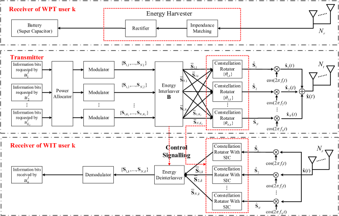
II-A1 Power Allocator
As illustrated in the middle of Fig. 1, the symbols requested by the WIT user are assigned allocated with different power on the -th sub-carrier, respectively. An appropriate power allocation scheme is capable of alleviating the mutual interference induced by the superposition symbol. More details will be provided in Section III-C.
II-A2 Modulator
Since the WIT receivers require the knowledge of the energy interleaver and the constellation rotators for the sake of successful demodulation, this knowledge also needs to be transmitted to the receivers as the control overhead. In order to reduce the control overhead, both the energy interleaving and the constellation rotation operate in a symbol-block level. Each symbol-block consists of modulated symbols. The transmitter generates modulated symbols for every WIT user, which are divided into symbol-blocks111The number of the symbol-blocks requested by a WIT user is equal to the number of sub-carriers.. The symbol-blocks requested by WIT user are denoted as , which is originally scheduled to be transmitted on the -th carrier222This scheduling may be altered by the energy interleaver..
For the modulated symbols transmitted on the -th sub-carrier to the WIT user , the minimum Euclidean distance in the constellation is . Without loss of generality, M-QAM modulator is adopted as a case study in this manuscript, since it has been widely adopted in modern wireless communications, e.g. the Long Term Evolution (LTE) and 802.11 based system. Specifically, when the M-QAM is adopted, we have [34]. If the symbol-block is transmitted to the WIT user on the -th sub-carrier, the -th symbol within it can be expressed as
| (1) |
for , where represents the phase, represents the amplitude normalised by . Moreover, and are the normalised amplitudes of in-phase and quadrature in the constellation of M-QAM, respectively. Specifically, we have .
II-A3 Energy Interleaver
The symbol-blocks requested by all the WIT users flow into an energy interleaver for the following pair of purposes:
-
•
Converting the serial symbol-blocks requested by every WIT user into the parallel ones.
-
•
Scheduling the transmissions of all the symbol-blocks on the sub-carriers. The scheduling scheme should avoid the superposition of the symbols having opposite phases, since it may degrade the actual energy carried by the resultant superposition symbols.
The energy interleaver can be represented by a three-dimensional binary tensor having the size of , where indicates that the symbol-block is transmitted on the -th sub-carrier, while indicates that is not transmitted on the -th sub-carrier. After the energy interleaving, all the symbol-blocks are scheduled on the sub-carriers. The symbol-block requested by WIT user is denoted as , which is transmitted on the -th sub-carrier.
II-A4 Constellation Rotator
After the energy interleaving, the modulated symbol-blocks transmitted on every sub-carrier then flow into the respective constellation rotator, as portrayed in the middle of Fig. 1. The symbol-blocks requested by different WIT users are then rotated with some certain angles, respectively, in order to counteract the energy degradation induced by superimposing the symbols having opposite phases. After the constellation rotation, the symbol-block is then converted to . The constellation rotation angles are also represented by a matrix having the size of , in which indicates the constellation rotation angle of the symbol-block .
Finally, all the rotated symbol-blocks are superimposed together. The resultant superposition symbol-block is represented by . After being modulated onto the -th sub-carrier, the corresponding signal is then broadcast to all the WIT and WPT users.
II-B Receiver Architecture of WIT users
The receiver architecture of the WIT users is illustrated in the bottom of Fig. 1. At the receiver of WIT user , the superposition symbol-blocks transmitted on sub-carriers are firstly recovered from the received analogue signal. Then, these symbol-blocks are further processed by the constellation rotation based SIC in order to extract the symbols requested by , as presented in the bottom of Fig. 1.
II-B1 Constellation Rotation Based SIC
According to the classic SIC, the symbols having the higher power should be firstly demodulated. Without loss of generality, we assume on each sub-carrier. Accordingly, the minimum Euclidean distances of the WIT users’ constellations satisfy the inequality of . Then, the WIT user demodulates its requested symbol-block on the -th sub-carrier by obeying the following steps:
-
•
Step 1: Initialize the label of the firstly demodulated WIT user as ;
-
•
Step 2: Rotate the superposition symbol-block with an angle of ;
-
•
Step 3: Recover the symbol-block according to the maximum-likelihood (ML) algorithm [35], by regarding the symbol-blocks of all the other WIT users in as the interference. If , then is the symbol-block requested by on the -th sub-carrier. Otherwise, remove from and come back to Step 2 by setting .
II-B2 Energy Deinterleaver
After the constellation rotation based SIC, the recovered symbol-blocks of on all the sub-carriers are then processed by an energy deinterleaver for the following purposes:
-
•
Convert the parallel symbol-blocks to the serial ones.
-
•
Sort the symbol-blocks to their original order according to generated at the transmitter.
The sorted symbol-blocks after the energy deinterleaver are represented by . After the demodulation, these symbols are finally decoded into information bits.
II-C Receiver Architecture of WPT users
The receiver architecture of WPT users is illustrated in the top of Fig. 1. The WPT users only harvest energy from the superposition signal destined to the WIT users by exploiting the broadcast nature of wireless channel. A typical energy harvester consists of an impendance matching circuit and a rectifier [10]. The impedance matching circuit guarantees an efficient energy transfer from the receive antennas to the electronic loads, while the rectifier converts the RF signals into the direct current (DC), whose energy can be finally stored in the battery or in the super capacitor.
The energy harvesters of the WPT users can only be activated, if the power of the received superposition signal is higher than a threshold , which is also regarded as the sensitivity of the energy harvester [36]. For simplicity, we assume an identical sensitivity for the energy harvesters of all the WPT. Specifically, the actual energy harvested by the WPT user within a symbol duration is , where is the received power of the superposition signal, is an indicator function, which is one only when the bracketed condition is satisfied, but zero, otherwise.
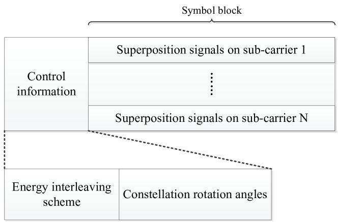
II-D Control signal
For the sake of symbol demodulation and of reordering the interleaved symbol blocks, the WIT users have to be aware of the energy interleaving schemes and constellation rotation angles adopted by the transmitter. As a result, these control signalling overhead has to be transferred from the transmitter to the WIT users before actual data transmission, which is portrayed in Fig. 2. These control signalling overhead can be compressed by adopting some appropriate encoding methods. For example, we have symbol block allocation schemes in total for a specific WIT user, since the transmitter has to establish a one-on-one mapping between symbol block of this WIT user and sub-carriers. Therefore, the energy interleaving matrix can be encoded into a binary sequence having a length of , where indicates the minimum integer not lower than . For the constellation rotation angles, we may divide the range of into non-overlapping regions, namely . Since constellation rotation angles are relative to one another, we may keep the constellation of an arbitrary WIT user unchanged while rotating the constellation of the other WIT users by certain angles. Therefore, all the constellation rotation angles of the WIT users can be encoded as a binary sequence having a length of .
III Specification of Key Functional Modules
In this section, we will specify the key operations in the transmitter, which includes the energy interleaving, the constellation rotation and the power allocation.
III-A Energy Interleaving
The energy interleaving is adopted at the transmitter in order to prevent the destructive superposition of the symbol-blocks requested by different WIT users on a single sub-carrier. Specifically, the WIT user requests symbol-blocks of on sub-carriers, as portrayed in Fig. 1. The transmitter has to carefully map these symbol-blocks onto the sub-carriers. Each symbol-block is only allowed to be scheduled on a single sub-carrier. The transmitter superimposes symbol-blocks requested by WIT users on every sub-carrier by adopting the power-domain NOMA. However, superimposing the symbols having various amplitudes and phases sometimes results in substantial degradation of the energy carried by the resultant superposition symbol, particularly when the symbols requested by the WIT users have opposite phases. As a result, we have to design an efficient interleaving scheme in order to appropriately map the symbol-blocks onto the sub-carriers and to avoid the degradation of the energy carried by the resultant superposition signal, which is regarded as the energy interleaving.
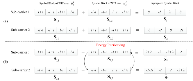
Observe from Fig. 3(a) that when we do not adopt the energy interleaving, the energy carried by the superposition symbol-blocks and is substantially reduced. This is because some of the symbols in the blocks of and and some in and have opposite phases. By contrast, observe from Fig. 3(b) that when the energy interleaving is adopted, the transmitter may map the symbol-block onto the first sub-carrier and map the symbol-block onto the second sub-carrier. Therefore, the resultant superposition symbol-blocks and still carries considerable energy. As a result, the energy interleaving substantially increases the WPT performance of the superposition symbols.
According to the energy interleaving tensor , we have
| (2) |
Furthermore, the -th symbol in the block can be expressed as
| (3) |
In (III-A), and are the normalised amplitude and phase of the symbol , which are formulated as
| (4) |
III-B Constellation Rotation
Constellation rotation aims for avoiding the destructive superposition among the symbol-blocks transmitted on a single sub-carrier by rotating the symbol blocks requested by different WIT users with different angles. As a result, the WPT performance of the resultant superposition symbol-block can be substantially improved.
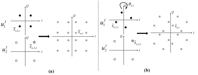
The symbol superposition between a pair of WIT users with and without the constellation rotation has been exemplified in Fig. 4. Specifically, observe from Fig. 4(a) that the actual power carried by the superposition symbol is lower than the sum power of the individual symbols and . The opposite phases of and substantially impair the attainable WPT performance. By contrast, if we rotate ’s constellation with a certain angle , while keeping the constellation of the WIT user unchanged, we may observe from Fig. 4 that the resultant superposition symbol after the constellation rotation carries a higher power than its counterpart .
After the constellation rotation, the symbol-block is converted into
| (5) |
where represents the rotation angle for all the symbols in the symbol-block . The -th symbol in is thus formulated as
| (6) |
Then, after the superposition of the WIT users’ symbol-blocks, the resultant superposition symbol-block transmitted on the -th sub-carrier is formulated as
| (7) |
Moreover, the -th superposition symbol in is derived as
| (8) |
where we have and .
Finally, the modulated RF signal corresponding to the superposition symbol can be formulated as
| (9) |
III-C Power Allocation for WIT Assurance
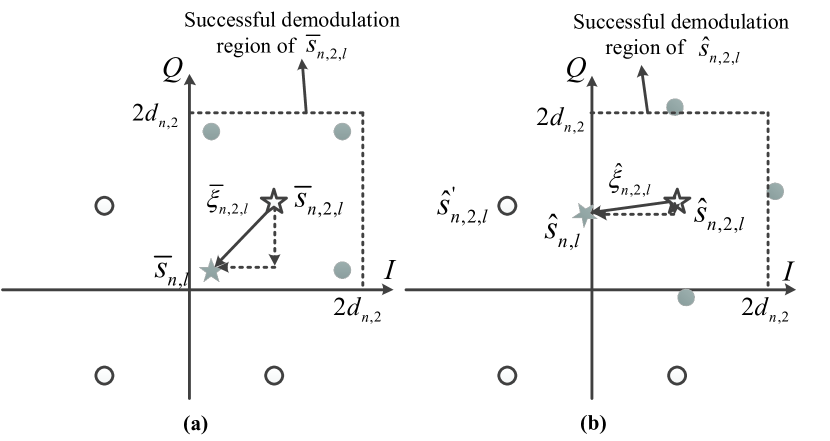
Although the attainable WPT performance can be increased by the constellation rotation, it may incur the adverse symbol offset, which may degrade the associated WIT performance. According to the SIC, when demodulating the symbol (or ), its counterpart (or ) is regarded as interference, as exemplified in Fig. 5. Observe from Fig. 5(a) that without the constellation rotation, the superposition symbol is still within the successful demodulation region of . By contrast, in the case of the constellation rotation, the superposition symbol is drifted beyond the successful demodulation region of , as presented in Fig. 5(b), which substantially degrades the demodulation performance of the symbol . Since we adopt the SIC for sequentially demodulating the symbols requested by different WIT users, we may suffer from severe error propagation when we demodulate the symbols of the rest of WIT users.
According to the SIC , after demodulating the symbol-blocks requested by other WIT users and remove them from the superposition symbol, the WIT user then rotates the residual superposition symbol with an angle of for demodulating its own requested symbol-block , according to the SIC specified in Section II-B-1. As a result, the distortion induced by the -th symbols belonging to the blocks on the -th symbol belonging to the block can be formulated as
| (10) |
where represents the in-phase component of the distortion vector and represents the corresponding component in the quadrature phase. In order to reduce the SER of the WIT user , the distortion induced by the symbol superposition should be carefully controlled. Therefore, the residual superposition symbol should be still within the successful demodulation region of the symbol requested by the WIT user , which can be represented by a square having the side length of , as exemplified in Fig.5. The constraints on the symbol distortion is then formulated as
| (11) |
for , , , where indicates the absolute value of the complex number .
In order to satisfy the symbol distortion constraint of (11), we opt to control the transmit power allocated to the symbols requested by all the WIT users. As a result, the constellation rotation angles may gain the highest degree of freedom for the sake of maximising the energy carried by the superposition symbol. The following theorem thus provides a feasible power allocation scheme:
Theorem 1
In order to satisfy the symbol distortion constraint of (11), the transmit power of the symbols requested by all the WIT users should satisfy the following inequality:
| (12) |
for , where represents the normalised maximum amplitude, when the M-QAM is adopted for generating the modulated symbols.
Proof:
Please refer to Appendix A for detailed proof. ∎
In order to guarantee the fairness among users but to satisfy the symbol distortion constraint (11), we take the equality of (12). Therefore, the transmit power of the symbols requested by the WIT user can be expressed as
| (13) |
Given the total transmit power on the -th sub-carrier, the transmit power of the symbols requested by the WIT users can be thus formulated as
| (14) |
IV Optimal Design of Energy Interleaver and Constellation Rotator
IV-A Problem Formulation
The actual energy carried by the -th superposition signal transmitted to all the WIT users on the -th sub-carrier can be expressed as (15).
| (15) |
Given the specific power allocation scheme (14) among the symbols requested by different WIT users, the joint design of the energy interleaver and the constellation rotator for maximising the energy carried by the superposition symbols on the multi-carriers can be formulated as
| (16) | |||
| (16a) | |||
| (16b) | |||
| (16c) | |||
| (16d) |
where (16a) and (16b) constraint the optional range of and , (16c) and (16d) indicate that for a single WIT user , only a single symbol-block is allowed to be transmitted on a single sub-carrier.
The optimisation problem (P1) is a mixture of integer and real number programming. It’s impossible to obtain a closed-form solution. This problem can be addressed by sequentially solving sub-problem of the constellation rotator design and that of the energy interleaver design. Note that our design actually maximises the total energy carried by the multi-carrier signal before it goes to the radio front, as illustrated in Fig.1. Therefore, our design may naturally adapt to any arbitrary number of antennas.
IV-B Constellation Rotator Design
IV-B1 Utility Function
Given a specific energy interleaver , the original optimisation problem (P1) can be simplified as
| (17) |
As portrayed in Fig.1, every sub-carrier has a constellation rotator. Therefore, the constellation rotator design on a specific sub-carrier is independent with others. As a result, the optimisation problem (P2) can be further decomposed into sub-problems in order to obtain the optimal constellation rotation angles for every WIT user on the sub-carriers, respectively. Specifically, the optimal constellation rotator design on the -th sub-carrier can be formulated as
| (18) |
Given the symbol-blocks transmitted on the -th sub-carrier, the utility function of this sub-carrier can be defined as , where is the resultant maximum by solving the problem (P3).
Observe from (P3) and (15) that the non-convex cosine function exists in the objective of (18). As a result, the optimisation problem (P3) is not convex and we cannot solve it by exploiting the convex optimisation. However, we may obtain its sub-optimal solution by exploiting the method of alternating optimisation [37].
IV-B2 Iterative Algorithm
The iterative algorithm for solving (P3) has the following steps:
-
•
Step 1: Randomly initialise the constellation rotation angles according to the constraint (16a).
-
•
Step 2: Optimise the constellation rotation angle for the symbols requested by the WIT user for by solving (P3), when the other angles are regarded as constants. According to the trigonometry, the optimal rotation angle is derived as
(19) where , and .
-
•
Step 3: Sequentially optimise the rotation angles for all the WIT users by using the same method of Step 2.
-
•
Step 4: Repeat Steps 3 and 4 until the constellation rotation angles converge to their optimums .
The pseudo code of the iterative algorithm is then provided in Algorithm 1.
INPUT:
User number ; Symbol blocks ; Convergence accuracy ;
OUTPUT:
Constellation rotation angles .
In Step 2 of every iteration, we may obtain the optimal solution of , although the problem is non-convex. We let represent the energy carried by the superposition symbol on the -th sub-carrier, when is updated at the -th iteration according to Algorithm 1. The following inequalities can be readily obtained:
| (20) |
This is because in every round of optimisation, the objective of (P3) is a non-decreasing function. Furthermore, according to (15), we also have
| (21) |
which indicates that is an increasing function with respect to the iteration round , while is also upper-bounded. Therefore, Algorithm 1 finally converges as the iteration round increases. When the algorithm converges, it returns us the sub-optimal solution.
IV-C Energy Interleaver Design
The utility of a specific symbol-blocks’ transmission arrangement on the -th sub-carrier can be characterised by the function of , which is obtained by solving problem (P3). Since the transmission arrangement of the symbol-blocks on all the sub-carriers is determined by the energy interleaving tensor , the utility function of the -th sub-carrier can also be expressed as . Furthermore, the optimal constellation rotation angles are also functions of the energy interleaving tensor . Therefore, the original optimisation problem (P1) can be simplified as
| (22) |
in which the energy interleaver tensor is the only parameter needs to be optimised for maximising the total energy transferred by the transmitter.
Since is a binary tensor having all its elements either 0 or 1, the optimisation problem (P4) is an integer programming problem. The exhaustive searching can be relied upon for the sake of obtaining the optimal solution.
IV-C1 Exhaustive Searching
A specific WIT user requests symbol-blocks on the sub-carriers in total. A single symbol-block of this WIT user is only allowed to be transmitted on a single sub-carrier. Therefore, we have schemes for mapping the symbol-blocks of the WIT user to the sub-carriers. We denote having the size of as the feasible searching space for the energy interleaver tensor , where the element represents a symbol-block-to-sub-carrier mapping scheme for the WIT user . We then traverse all the feasible mapping schemes for every WIT user and choose the optimal one for maximising the objective of (P4). The complexity of the exhaustive searching is as high as . Although may not be very large in a power-domain NOMA systems, the complexity will be substantially increased, if we have more sub-carriers.
IV-C2 Greedy Algorithm
In order to reduce the complexity of the exhaustive searching, another greedy algorithm is proposed by sacrificing some optimality of the solution. The main steps of the greedy algorithm is summarised as below:
-
•
Step 1: Initialise the optimal utility function of every sub-carrier as for . A binary matrix having the size of is defined. Its element indicates that the -th symbol-block of has already been scheduled on a specific sub-carrier but represents that the -th symbol-block has not been scheduled on any sub-carrier. All the elements in are initialised as . Only the symbol-blocks having the indicators of can be scheduled on the free sub-carriers. With the aid of , it can be thus guaranteed that each symbol-block requested by is scheduled on a single sub-carrier.
-
•
Step 2: When we start to schedule the symbol-blocks of WIT users on the -th sub-carrier, the first sub-carriers have already accepted the transmissions of symbol-blocks for each. Accordingly, the WIT user only has symbol-blocks to be scheduled, whose binary indicators in the matrix are all zeros. Hence, we have possible schemes in total for scheduling the rest of symbol-blocks of all the WIT users on the -th sub-carrier. We denote all these scheduling schemes as a set .
-
•
Step 3: We then traverse all the scheduling schemes in the set and find the optimal one for maximising the objective of (P4). When a specific scheduling scheme is chosen, the symbol-blocks scheduled on the -th sub-carrier are thus determined, which can be denoted as . Therefore, we are capable of calculating the utility function of the -th sub-carrier. Finally, the optimal scheduling scheme on the -th sub-carrier can be found for the sake of maximising its utility function. In order to prevent these symbol-blocks from being scheduled again, we update the corresponding indicators in the matrix .
The pseudo code of the greedy algorithm is provided in Algorithm 2. The proposed greedy algorithm concludes after iterations. Its complexity is , which is substantially lower than of the exhaustive searching.
INPUT:
User number ;
Sub-carrier number ;
Symbol blocks ;
OUTPUT:
Optimal energy interleaving tensor .
V Simulation Results
Without specific statement, the parameters in our simulation are set as follows: We have WIT users and WPT user in the NOMA-SWIPT system. The classic additive white Gaussian noise (AWGN) channels are conceived between the transmitter and the WIT/WPT users, while the noise power is set to be dBm. The channel power gain between the WPT user and the H-AP is dB, while those between the WIT users and the H-AP are dB, respectively. The transmitter has modulated symbols to be transmitted to every WIT user, which are randomly generated by the QAM based modulator. The symbol duration is set to be s. There are 10 sub-carriers in the simulation. The total transmit power on every sub-carrier is all W.
V-A Convergence and Validity
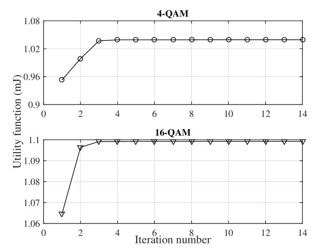
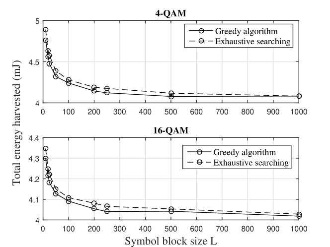
We firstly investigate the convergence of Algorithm 1 in Fig. 6, where we maximise the energy carried by a specific sub-carrier by solving the optimisation problem (P3). Observe from Fig. 6 that Algorithm 1 converges within 5 iterations at most, when the 4-QAM and 16-QAM are adopted. Furthermore, we compare the WPT performance of the greedy algorithm and the exhaustive searching based algorithm for solving the problem (P4) in Fig. 7, where we consider sub-carriers in total. Observe from Fig. 7 that the WPT performance of the greedy algorithm is almost the same as that of the exhaustive searching. Therefore, in the rest of simulation, the greedy algorithm is adopted for solving the optimisation problem (P1), since its complexity is far lower than the exhaustive searching based counterpart.
V-B WPT Performance
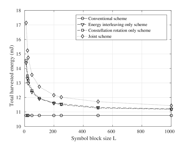
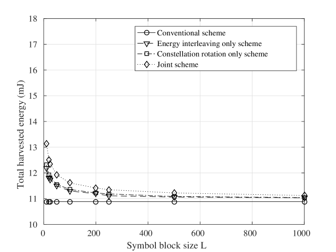
We evaluate the total energy harvested by the WPT user in Fig. 8-9 by invoking the following different interleaving and modulation schemes:
-
•
Conventional scheme: Neither energy interleaving nor constellation rotation is invoked;
-
•
Energy interleaving only scheme: constellation rotation is not invoked;
-
•
Constellation rotation only scheme: energy interleaving is not invoked;
-
•
Joint scheme: both interleaving and constellation rotation are invoked.
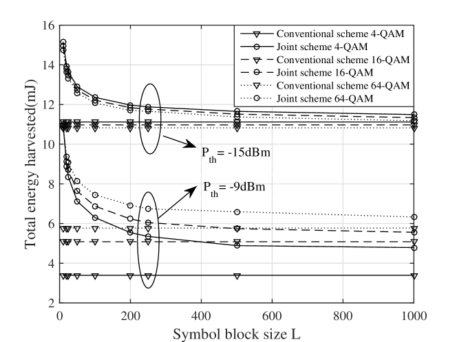
Observe from Fig. 8-9 that the joint scheme achieves the highest WPT performance for both the 4-QAM and 16-QAM. Moreover, the energy interleaving only scheme and the constellation rotation only scheme achieve the moderate WPT performance, which is still much higher than the conventional scheme. Furthermore, the WPT performance of the conventional scheme keeps constant but that of all the other three schemes all reduces, as the symbol-block size increases. This is because a lower value of represents that the transmitter may update the energy interleaver and the constellation rotator more frequently, which results in more constructive symbol superposition. However, when we update the energy interleaver and the constellation rotator more frequently, more control signalling has to be transmitted to the WIT receivers, since the knowledge of the energy interleaver and the constellation rotators is indispensable for the demodulation and deinterleaving. Therefore, it’s important to design an appropriate symbol-block size for the sake of compromising between the WPT performance and the control signalling overhead. By contrast, the WPT performance of the conventional scheme is not affected by the symbol-block size .
Moreover, observe from Fig. 8-9 that the 4-QAM based modulator achieves a higher WPT performance than the 16-QAM based modulators. According to the power allocation scheme of (13), when the higher order modulation is adopted, also becomes higher, which indicates that the power difference among the symbols requested by different WIT users is enlarged. As a result, when we have a fixed total transmit power, the WPT performance gain incurred by the energy interleaving and the constellation rotation becomes lower, since the energy carried by a symbol having a very high power cannot be substantially degraded by a symbol having a very low power after their superposition. Under this consideration, if we want to achieve a higher energy harvesting gain, a lower rate is a better choice.
V-C Sensitivity of Energy Harvester
We investigate the impact of energy harvester’s sensitivity in Fig. 10. The power allocation scheme is derived by substituting of the 64-QAM into (13). The same power allocation scheme is also invoked for both the 4-QAM and 16-QAM in order to minimise the effect of the power difference on the attainable WPT performance. Observe from Fig. 10 that when the energy harvester’s sensitivity is low, say dBm, the 4-QAM achieves the highest WPT performance, while the 64-QAM achieves the lowest WPT performance. When increases to -9 dBm, we observe an inverse trend from Fig. 10. This is because a modulation scheme of high order may generate a lot of symbols carrying lower power than the rectifier’s sensitivity. The energy carried by these symbols cannot be harvested by the WPT user. By contrast, a modulation scheme of lower order generate symbols carrying almost identical power. If the sensitivity is low, all the symbols can be relied upon for energy harvesting. However, when the sensitivity is high, none of the symbols generated by a low-order modulation scheme are capable of delivering energy to the WPT users. By contrast, since a high-order modulation scheme may generate some symbols carrying very high power, these symbols can still deliver some energy to the WPT users.
V-D WIT Performance
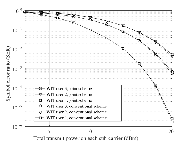
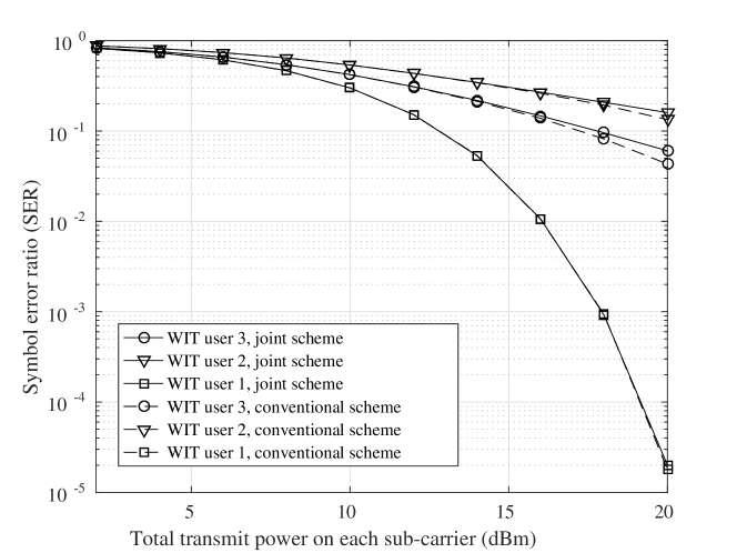
Finally, we plot the SER performance of the joint and conventional schemes versus the total transmit power on each sub-carrier in Fig. 11-12, when 4-QAM and 16-QAM are adopted, respectively. In this simulation, the transmitter has modulated symbols to be transmitted to each WIT user in order to achieve more accurate results. Observe from Fig. 11-12 that the joint scheme has almost the same SER performance as the conventional scheme, when the 4-QAM is adopted. When the 16-QAM are adopted, the joint scheme only suffers from a tiny degradation of the SER performance, when compared to the conventional counterpart.
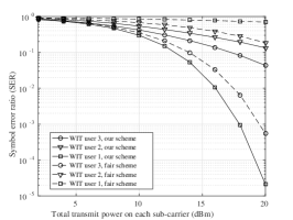
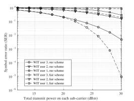
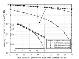
We also compared the SER performance in Fig. 13 between our scheme and another fair scheme proposed in [38], where the power allocation scheme is designed by letting the signal to interference and noise ratio (SINR) of all the WIT users be the same. Observe from Fig. 13 that when 16-QAM is adopted, for WIT user 3 having the worst channel condition, our scheme achieves a higher SER than the counterpart. However, for WIT user 1 having the best channel condition, our power allocation scheme achieves a much lower SER than the fair scheme. When 64-QAM is adopted, our scheme achieves lower SER differences among WIT users than the counterpart. Moreover, observe from Fig. 13(c) that our power allocation scheme achieves lower average SER among all the WIT users than the fair scheme. In a nutshell, our power allocation scheme outperforms the benchmark of [38] in terms of the SER fairness.
V-E Spectrum Efficiency
Let us now discuss the spectrum efficiency of our NOMA-SWIPT system. As for the WIT user , the total achievable throughput is formulated as
where is the bandwidth of a single sub-carrier. Therefore, the spectrum efficiency of the system is derived as
In our simulation, the spectrum efficiency is thus calculated as , which is around higher than of the OFDMA based counterpart. Meanwhile, observe from Fig. 8-9 that if the symbol block size is set to be , our joint design is capable of achieving and higher WPT performance than the conventional scheme, when 4-QAM and 16-QAM are adopted, respectively.
VI Conclusion
In this paper, we jointly design the energy interleaving and the constellation rotation in a multi-user NOMA-SWIPT system. In our design, the energy interleaving tensor as well as the constellation rotation angles are optimised for maximising the actual energy carried by the superposition signals. Furthermore, a power allocation scheme among the symbols requested by the WIT users is proposed for the sake of reducing the SER of the WIT users, when the SIC is adopted for the demodulation of the superposition symbols. The simulation results demonstrate that our joint design is capable of substantially increasing the attainable WPT performance, while the SER degradation can be rigorously controlled. Furthermore, our simulation results also demonstrate that for a more sensitive energy harvester associated with a higher activation threshold, the higher-order modulation scheme outperforms its low-order counterparts. By contrast, for an energy harvester having a lower activation threshold, the lower-order modulation scheme performs better than its high-order counterparts.
Appendix A
For an arbitrary WIT user , the distortion constraint (11) has to be satisfied in order to reduce the distortion incurred by the other symbols requested by the WIT users in the SIC aided demodulation. In the worst case, the symbol distortion of (III-C) is maximised, when its in-phase component and quadrature component both achieve their maximums. As a result, the symbols transmitted to the WIT users all have the highest normalised amplitudes, say , while they also have the same phase, say . Since we have
| (23) |
the symbol distortion constraint (11) can be reformulated as
| (24) |
Since is a linear function of , we can readily obtain the constraint (12) on the transmit power of the symbols requested by different WIT users.
References
- [1] G. Zhang, K. Yang, P. Liu, and J. Wei, “Power allocation for full-duplex relaying-based D2D communication underlaying cellular networks,” IEEE Transactions on Vehicular Technology, vol. 64, no. 10, pp. 4911–4916, Oct 2015.
- [2] K. Wang, K. Yang, and C. S. Magurawalage, “Joint energy minimization and resource allocation in C-RAN with mobile cloud,” IEEE Transactions on Cloud Computing, vol. 6, no. 3, pp. 760–770, July 2018.
- [3] G. Xu, H. Li, Y. Dai, K. Yang, and X. Lin, “Enabling efficient and geometric range query with access control over encrypted spatial data,” IEEE Transactions on Information Forensics and Security, vol. 14, no. 4, pp. 870–885, 2019.
- [4] Z. Ding, X. Lei, G. K. Karagiannidis, R. Schober, J. Yuan, and V. K. Bhargava, “A survey on non-orthogonal multiple access for 5G networks: Research challenges and future trends,” IEEE Journal on Selected Areas in Communications, vol. 35, no. 10, pp. 2181–2195, Oct 2017.
- [5] Z. Ding, Y. Liu, J. Choi, Q. Sun, M. Elkashlan, I. Chih-Lin, and H. V. Poor, “Application of non-orthogonal multiple access in LTE and 5G networks,” IEEE Communications Magazine, vol. 55, no. 2, pp. 185–191, 2017.
- [6] Y. Huang, C. Zhang, J. Wang, Y. Jing, L. Yang, and X. You, “Signal processing for MIMO-NOMA: Present and future challenges,” IEEE Wireless Communications, vol. 25, no. 2, pp. 32–38, April 2018.
- [7] M. Zeng, A. Yadav, O. A. Dobre, and H. V. Poor, “Energy-efficient power allocation for MIMO-NOMA with multiple users in a cluster,” IEEE Access, vol. 6, pp. 5170–5181, 2018.
- [8] L. Zhang, J. Liu, M. Xiao, G. Wu, Y. C. Liang, and S. Li, “Performance analysis and optimization in downlink NOMA systems with cooperative full-duplex relaying,” IEEE Journal on Selected Areas in Communications, vol. 35, no. 10, pp. 2398–2412, Oct 2017.
- [9] X. Zhou, C. K. Ho, and R. Zhang, “Wireless power meets energy harvesting: A joint energy allocation approach in OFDM-based system,” IEEE Transactions on Wireless Communications, vol. 15, no. 5, pp. 3481–3491, May 2016.
- [10] J. Hu, K. Yang, G. Wen, and L. Hanzo, “Integrated data and energy communication network: A comprehensive survey,” IEEE Communications Surveys Tutorials, vol. 20, no. 4, pp. 3169–3219, Fourthquarter 2018.
- [11] H. Lee, K. J. Lee, H. Kim, and I. Lee, “Joint transceiver optimization for MISO SWIPT systems with time switching,” IEEE Transactions on Wireless Communications, vol. 17, no. 5, pp. 3298–3312, May 2018.
- [12] Z. Hu, C. Yuan, and F. Gao, “Maximizing harvested energy for full-duplex SWIPT system with power splitting,” IEEE Access, vol. 5, pp. 24 975–24 987, 2017.
- [13] S. Guo, H. Zhang, Y. Wang, and D. Yuan, “Spatial modulated simultaneous wireless information and power transfer,” in 2016 IEEE Global Communications Conference (GLOBECOM), Dec 2016, pp. 1–6.
- [14] Y. Zhao, J. Hu, Y. Diao, Q. Yu, and K. Yang, “Modelling and performance analysis of wireless lan enabled by RF energy transfer,” IEEE Transactions on Communications, vol. 66, no. 11, pp. 5756–5772, Nov 2018.
- [15] Z. Yang, Z. Ding, P. Fan, and N. Al-Dhahir, “The impact of power allocation on cooperative non-orthogonal multiple access networks with SWIPT,” IEEE Transactions on Wireless Communications, vol. 16, no. 7, pp. 4332–4343, July 2017.
- [16] Y. Liu, Z. Ding, M. Elkashlan, and H. V. Poor, “Cooperative non-orthogonal multiple access with simultaneous wireless information and power transfer,” IEEE Journal on Selected Areas in Communications, vol. 34, no. 4, pp. 938–953, April 2016.
- [17] Y. Xu, C. Shen, Z. Ding, X. Sun, S. Yan, G. Zhu, and Z. Zhong, “Joint beamforming and power-splitting control in downlink cooperative SWIPT NOMA systems,” IEEE Transactions on Signal Processing, vol. 65, no. 18, pp. 4874–4886, Sept 2017.
- [18] P. D. Diamantoulakis, K. N. Pappi, Z. Ding, and G. K. Karagiannidis, “Wireless-powered communications with non-orthogonal multiple access,” IEEE Transactions on Wireless Communications, vol. 15, no. 12, pp. 8422–8436, Dec 2016.
- [19] Y. Alsaba, C. Y. Leow, and S. K. A. Rahim, “Full-duplex cooperative non-orthogonal multiple access with beamforming and energy harvesting,” IEEE Access, vol. 6, pp. 19 726–19 738, 2018.
- [20] M. Hedayati and I. Kim, “On the performance of NOMA in the two-user SWIPT system,” IEEE Transactions on Vehicular Technology, vol. 67, no. 11, pp. 11 258–11 263, Nov 2018.
- [21] L. Dai, B. Wang, M. Peng, and S. Chen, “Hybrid precoding-based millimeter-wave massive MIMO-NOMA with simultaneous wireless information and power transfer,” IEEE Journal on Selected Areas in Communications, vol. 37, no. 1, pp. 131–141, Jan 2019.
- [22] W. Wu, X. Yin, P. Deng, T. Guo, and B. Wang, “Transceiver design for downlink SWIPT NOMA systems with cooperative full-duplex relaying,” IEEE Access, vol. 7, pp. 33 464–33 472, 2019.
- [23] J. Hu, Y. Zhao, and K. Yang, “Modulation and coding design for simultaneous wireless information and power transfer,” IEEE Communications Magazine, vol. 57, no. 5, pp. 124–130, May 2019.
- [24] C. C. Cheng, M. D. Renzo, F. Graziosi, and A. Zappone, “On simultaneous wireless information and power transfer for receive spatial modulation,” IEEE Access, vol. 5, pp. 23 204–23 211, 2017.
- [25] L. Mohjazi, S. Muhaidat, and M. Dianati, “Performance analysis of differential modulation in SWIPT cooperative networks,” IEEE Signal Processing Letters, vol. 23, no. 5, pp. 620–624, May 2016.
- [26] C. Jiang and Z. Wu, “A novel uplink noma scheme based on low density superposition modulation,” in 2017 IEEE 86th Vehicular Technology Conference (VTC-Fall), Sept 2017, pp. 1–5.
- [27] G. Niharika, “Performance comparison of modulation schemes for downlink NOMA,” in 2018 2nd International Conference on Inventive Systems and Control (ICISC), Jan 2018, pp. 1431–1433.
- [28] Y. Liu, L. Yang, and L. Hanzo, “Spatial modulation aided sparse code-division multiple access,” IEEE Transactions on Wireless Communications, vol. 17, no. 3, pp. 1474–1487, March 2018.
- [29] Y. Li and J. Moon, “Error probability bounds for bit-interleaved space ctime trellis coding over block-fading channels,” IEEE Transactions on Information Theory, vol. 53, no. 11, pp. 4285–4292, Nov 2007.
- [30] J. Ning and M. Fu, “Design of serially concatenated continuous phase modulation with symbol-wise interleaving,” IEEE Communications Letters, vol. 13, no. 10, pp. 785–787, October 2009.
- [31] N. Ye, A. Wang, X. Li, W. Liu, X. Hou, and H. Yu, “On constellation rotation of NOMA with SIC receiver,” IEEE Communications Letters, vol. 22, no. 3, pp. 514–517, March 2018.
- [32] C. Lin, S. Shieh, T. Chi, and P. Chen, “Optimal inter-constellation rotation based on minimum distance criterion for uplink NOMA,” IEEE Transactions on Vehicular Technology, vol. 68, no. 1, pp. 525–539, Jan 2019.
- [33] Y. Zhao, J. Hu, Z. Ding, and K. Yang, “Constellation rotation aided modulation design for the multi-user SWIPT-NOMA,” in 2018 IEEE International Conference on Communications (ICC), May 2018, pp. 1–6.
- [34] M. K. Simon and M. S. Alouini, Digital Communication over Fading Channels: A Unified Approach to Performance Analysis. Wiley.
- [35] M. Belebi and H. Arslan, “Theoretical analysis of the co-existence of LTE-A signals and design of an ML-SIC receiver,” IEEE Transactions on Wireless Communications, vol. 14, no. 8, pp. 4626–4639, Aug 2015.
- [36] J.-S. Yuan and E. Kritchanchai, “RF energy harvesting using emerging TFET technology,” in 2016 13th IEEE International Conference on Solid-State and Integrated Circuit Technology (ICSICT), Oct 2016, pp. 49–52.
- [37] J. C. Bezdek and R. J. Hathaway, “Convergence of alternating optimization,” Neural Parallel and Scientific Computations, vol. 11, no. 4, pp. 351–368, 2003.
- [38] S. Timotheou and I. Krikidis, “Fairness for non-orthogonal multiple access in 5G systems,” IEEE Signal Processing Letters, vol. 22, no. 10, pp. 1647–1651, Oct 2015.