Cooperative NOMA for Downlink Asymmetric Interference Cancellation
Abstract
This letter advances the non-orthogonal multiple access (NOMA) technique for cellular downlink co-channel interference mitigation, via exploiting the (limited) cooperation among base stations (BSs). Specifically, we consider a simplified but practically relevant scenario of two co-channel cells with asymmetric interference, i.e., only the user in one cell receives the strong interference from the BS in the other cell. To mitigate such interference, we propose a new cooperative NOMA scheme, where the interfered user’s serving BS sends a superposed signal comprising both the desired message and the co-channel user’s message (shared by the interfering BS). The co-channel user’s signal is aimed to add constructively with the interfering BS’s signal at the interfered user’s receiver so that the combined interference with enhanced power can be effectively decoded and cancelled. This thus leads to a new problem on how to optimally allocate the transmit power for the two superposed messages. We provide the closed-form solution to this problem and investigate the conditions under which the performance of the proposed scheme is superior over the existing schemes.
Index Terms:
Cooperative NOMA, cellular downlink, asymmetric interference cancellation, power allocation.I Introduction
Thanks to its ability to realize massive connectivity, low latency and high spectral efficiency in wireless communications, non-orthogonal multiple access (NOMA) technique has been recognized as a key enabler for future cellular networks. As such, NOMA has drawn a great deal of attention from both academia and industry (see, e.g., [1, 2, 3] and the references therein). However, most of the existing studies on NOMA are limited to the single-cell setup, while only a handful of works have recently addressed the more challenging multi-cell scenario (see e.g., [4, 5, 6, 7]). For multi-cell NOMA, inter-cell interference (ICI) is a major issue as it makes the successive interference cancellation (SIC) design far more complicated as compared to the single-cell case without ICI, especially for cell-edge user equipments (UEs) that generally suffer strong co-channel interference from other cells.
To resolve the above issue, NOMA has been combined with various interference mitigation techniques such as ICI coordination (ICIC) and cooperative multi-point (CoMP), generally referred to as cooperative NOMA, to reap its benefits as in the single-cell system. Specifically, cooperative NOMA involves multiple BSs to serve the cell-edge UEs at the same time by leveraging the message sharing among cooperating BSs. For example, in [4], the author proposed a coordinated superposition coding scheme in a two-cell downlink network, where a cell-edge UE is served by two BSs via Alamouti code. To reduce the complexity of multi-user NOMA, an opportunistic NOMA scheme was proposed in [5], where each cell-edge UE is allowed to select its own preferred set of serving BSs. Furthermore, the work [6] developed a general cooperation model with coexisting CoMP and non-CoMP UEs, and NOMA is applied at each BS to schedule their communications over the same resource block (RB). The authors in [7] proposed two interference alignment-based cooperative NOMA schemes so as to completely eliminate the ICI suffered by cell-edge UEs.
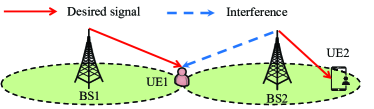
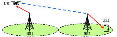
As shown in Fig. 1, we consider in this letter a simplified two-cell system with asymmetric interference, where only the downlink transmission from BS1 to UE1 is strongly interfered by that from BS2 to UE2. This scenario can occur in practice, e.g., when UE1 is at the cell edges of both BS1 and BS2 and the distance between BS1 and UE2 is much longer than that between BS1/BS2 and UE1 (see Fig. 1(a)). Alternatively, if UE1 is an unmanned aerial vehicle (UAV)[8], then it suffers much stronger ground-to-air interference from the co-channel BS2 as compared to the terrestrial interference caused by BS1 to UE2, even if UE1 (the UAV) is much closer to its serving BS (BS1) than the interfering BS (BS2), as shown in Fig. 1(b). This is because for high-altitude UAVs, their channels with ground BSs are dominated by line-of-sight (LoS) propagation[9], and thus suffer less path-loss, shadowing and multi-path fading as compared to the typical terrestrial channels (e.g., that between BS1 and UE2 in Fig. 1) with rich scatterers111Please refer to [8] and [10, 11, 12] for more details on the aerial-ground interference mitigation techniques for the downlink and uplink cellular UAV communications, respectively.. In both the above scenarios, despite that UE1 can perform SIC to subtract the interference from BS2, its achievable rate can be limited for satisfying the rate demand of UE2 due to the comparable signal and interference links from BS1 and BS2, respectively. To improve the rate performance of UE1 without affecting the co-channel transmission for UE2, we propose a new cooperation scheme by exploiting only one-sided message sharing from BS2 to BS1 (as opposed to the two-sided message sharing between the two BSs required by CoMP-based NOMA as in [4, 5, 6, 7]). Specifically, BS2 via the backhaul link shares the data symbol for UE2 with BS1, which then transmits a superposed signal comprising both UE1’s and UE2’s data symbols. As a result, UE2’s signal can be added destructively or constructively with BS2’s interference at UE1’s receiver to suppress it (for decoding UE1’s signal directly) or enhance it (for decoding and cancelling UE2’s signal first before decoding UE1’s signal), respectively. In both cases, BS1’s transmit power allocations for UE1’s and UE2’s signals need to be optimized accordingly to maximize the achievable rate of UE1. For the former case, the optimal power allocation has been derived in our prior work [8], while in this letter we address this problem in the latter case. Note that in this case, the proposed cooperative NOMA resembles the conventional NOMA [1, 2, 3] in the sense that BS1 sends a superposed signal of both UEs, and the near UE (UE1) applies SIC to decode and cancel the interference due to the far UE (UE2). However, a key difference between them lies in that the transmitted UE2’s signal in our scheme is not intended for UE2 (as in conventional NOMA), but instead for enhancing the combined interference at UE1’s receiver to facilitate its SIC. We compare the proposed cooperative NOMA scheme with other existing schemes both analytically and numerically to characterize the conditions under which it gives superior rate performance.
Notations: For a complex number , denotes its amplitude, denotes its phase, and means that it is a circularly symmetric complex Gaussian (CSCG) random variable with mean and variance . denotes the expected value of random variables.
II System Model and Problem Formulation
As shown in Fig. 1, we consider a two-cell setting222This is for the convenience of illustrating the proposed scheme, while we will leave the extension to the general multi-cell system for our future work., where two BSs (BS1 and BS2) serve their respective UEs (UE1 and UE2) in the downlink over the same time-frequency RB. We assume that each BS employs an antenna array with fixed directional gain pattern, while each UE has a single antenna. We consider the asymmetric interference scenario as explained in Section \@slowromancapi@, where UE1 receives the strong co-channel interference from BS2, while the interference from BS1 to UE2 is negligible and thus ignored. It is assumed that the downlink transmission from BS2 to UE2 has already started over the considered RB before BS1 serves UE1 using the same RB. As such, we consider that BS2 cannot change its transmission to UE2 and thus the CoMP-based cooperative NOMA[4, 5, 6, 7] is not applicable. Nonetheless, BS2 can help BS1 mitigate its interference to UE1 by sharing some useful information via their backhaul link (e.g., the X2 interface in Long Term Evolution (LTE)[13]), such as UE2’s data symbol and the channel gain from it to UE1, which thus enables our proposed cooperative NOMA scheme. For ease of reference, the main symbols used in this letter are listed in Table I.
| Symbol | Description |
|---|---|
| Maximum transmit power of BS1 | |
| Maximum transmit power of BS2 | |
| Baseband equivalent channel from BS1 to UE1 | |
| Baseband equivalent channel from BS2 to UE1 | |
| Complex data symbol for UE1 | |
| Complex data symbol for UE2 | |
| UE1’s receiver noise power | |
| UE1’s maximum SINR achievable by scheme | |
| Complex weight for transmitting by BS1 | |
| Complex weight for transmitting by BS1 | |
| Amplitude of of , i.e., | |
| Amplitude of of , i.e., | |
| Minimum SINR required for decoding UE2’s message |
II-A Conventional Schemes
First, we characterize the achievable signal-to-interference-plus-noise ratio (SINR) of UE1 via the conventional single-cell schemes by BS1 without BS2’s cooperation. Two schemes are considered, with or without SIC applied at UE1. Let be the complex-valued baseband equivalent channel gain from BS1 to UE1, and be that from BS2 to UE1. Let and denote the maximum transmit power of BS1 and BS2, respectively. Then, the received signal at UE1 can be expressed as
| (1) |
where denotes the transmit power of BS1, and denote the complex-valued data symbols for UE1 and UE2 with and , respectively, and denotes UE1’s receiver noise with denoting the power.
Scheme 1: If SIC is not implemented at UE1, then the co-channel interference is treated as Gaussian noise at its receiver. In this case, BS1 should transmit at its full power, i.e., , to maximize UE1’s receive SINR, which can be expressed as
| (2) |
Scheme 2: On the other hand, if UE1 first decodes UE2’s message and then subtracts it, UE1 will be free of co-channel interference. As a result, its receive SINR is given by
| (3) |
Note that to successfully cancel UE2’s signal, its receive SINR at UE1 is given by
| (4) |
As a result, the maximum receive SINR of UE1 under scheme 2 can be obtained by solving the following optimization problem
| (5) |
where denotes the minimum SINR required for decoding UE2’s message (say, at UE2’ receiver), which is assumed to be given and fixed. Obviously, (P-S2) is feasible if and only if . Assuming that (P-S2) is feasible, its optimal solution, denoted as , can be easily shown to be
| (6) |
Accordingly, its optimal value, denoted as , is given by
| (7) |
II-B Cooperation Schemes
Next, we consider the case where BS2 cooperatively sends and to BS1 to facilitate the interference cancellation at UE1. With available at BS1, it transmits the superposition of and , i.e., , where and denote the complex weights. To satisfy the power constraint at BS1, it must hold that . Then, the received signal at UE1 becomes
| (8) |
Based on (8), we introduce two interference cancellation schemes for UE1, depending on whether is designed to be in- or out-of-phase with the interference channel gain .
Scheme 3[8]: If is designed to be opposite to , i.e., , the interference due to at UE1 can be suppressed, and its receive SINR can be improved as compared to (2), which is given by
| (9) |
For convenience, let and be the amplitude of the complex weights and , respectively. Then the problem for maximizing (9) can be formulated as
| s.t. | (10) |
Notice that with in (P-S3), scheme 3 reduces to scheme 1. Consequently, the solution to (P-S3) should generally yield a higher receive SINR for UE1 than scheme 1 without BS2’s cooperation.
From [8], the optimal solution to (P-S3), denoted by , is given by
| (11) |
where . Moreover, UE1’s maximum receive SINR, denoted as , is given by
| (12) |
where . It is worth noting that SIC is not applied at UE1’s receiver in this scheme. Moreover, it is shown in [8] that monotonically increases with . This implies that if the interference power becomes stronger (relative to the desired signal power ), scheme 3 achieves lower SINR and thus becomes less effective.
Scheme 4: Note that in scheme 2, the use of SIC for canceling UE2’s signal at UE1 limits the achievable rate of UE1, especially when the desired signal power becomes comparable with the interference power or is large (i.e., when the first case in (7) is likely to be true). To improve over scheme 2, a new cooperative NOMA scheme, referred to as scheme 4, is proposed in this letter, where is designed to be in-phase with the interference channel gain , i.e., , for enhancing the combined interference due to UE2’s signal so as to cancel it more effectively by SIC at UE1’s receiver.
As a result, with scheme 4, UE1’s and UE2’s achievable SINRs with SIC can be expressed as
| (13) |
respectively. To ensure that UE2’s signal can be decoded, the following inequality should be met, i.e., .
The new power allocation problem for maximizing is thus formulated as
| s.t. | (14a) | |||
| (14b) | ||||
Notice that with in problem (P-S4), (P-S4) reduces to (P-S2). Consequently, the proposed cooperative NOMA scheme generally yields a higher SINR or achievable rate for UE1 than the conventional NOMA (scheme 2) without BS2’s cooperation.
III Optimal Solution and Performance Comparison
In this section, we first derive the optimal solution to (P-S4) which achieves the maximum receive SINR of UE1 by our proposed scheme (scheme 4). Then, we compare the performance of the proposed scheme with that of scheme 3 to reveal the conditions under which the proposed scheme achieves superior performance.
III-A Optimal Solution to (P-S4)
It is easy to show, by contradiction, that the constraint (14b) must hold with equality at the optimality of (P-S4), i.e., . Otherwise, we can construct a new solution with . Obviously, we have and
| (15) |
with . Since is a feasible solution to (P-S4), it should satisfy the constraint (14a), i.e., . Moreover, as , it follows that the right-hand side (RHS) of (15) is greater than . Hence, is a feasible solution to (P-S4). However, since , this new solution yields a larger objective value of (P-S4) than . This contradicts the presumption, and thus must hold at the optimality of (P-S4). By substituting into (P-S4), we obtain the following equivalent problem with only a single variable , i.e.,
| (16) |
where the constant term is omitted in the objective function. Since , the above problem is equivalent to
| (17) |
where .
It is easy to verify that as increases, the numerator and the denominator of increase and decrease, respectively. As such, is a monotonically increasing function of . It then follows that problem (17) is feasible if and only if , which can be shown equivalent to
| (18) |
Moreover, if , i.e., the optimal solution to problem (17) is , scheme 4 becomes equivalent to scheme 2. Finally, if , the optimal solution to (P2) should be the solution to the equation , or equivalently, the quadratic equation , where
| (19) |
Since , the quadratic equation only has a single positive root, which is the optimal solution to problem (16) and given by
| (20) |
where .
Correspondingly, if scheme 4 is feasible, i.e., , UE1’s maximum receive SINR can be expressed as
| (21) |
It follows from (20) that when the interference power increases, the numerator of decreases. As such, monotonically decreases with . This implies that UE1’s maximum receive SINR, as given in (21), is non-decreasing with . This is in a sharp contrast to scheme 3 for which UE1’s maximum receive SINR, i.e., in (12), decreases with . The above observations imply that our proposed scheme (scheme 4) is more advantageous over scheme 2 or 3 when is larger or the interference power is larger, respectively.
III-B Performance Comparison
Since scheme 2 is a special case of scheme 4, while scheme 1 is a special case of scheme 3, it suffices to compare the performance of our proposed scheme 4 with that of scheme 3 analytically, as pursued in this subsection. For convenience, we define and .
To this end, we compare (12) with (21). Firstly, if , scheme 4 (or scheme 2) outperforms scheme 3 as . Secondly, if , it can be shown that if , where . Since is the unique positive root of the quadratic equation , the above inequality holds if and only if , which, after some manipulations, can be shown equivalent to
| (22) |
where .
By combining the results in the above two cases, it follows that scheme 4 yields a better performance than scheme 3 if the condition (22) is met. Since and monotonically increase and decrease with the interference power , respectively, the threshold given in the RHS of (22) must monotonically increase with or the interference power at UE1, , which is in accordance with our previous discussion at the end of Section III-A, as will be also shown via numerical results in the next section.
IV Numerical Results
In this section, numerical results are provided to evaluate the performance of the proposed cooperative NOMA scheme (scheme 4), as compared to the benchmark schemes 1, 2 and 3. We consider a cellular-connected UAV for UE1, while UE2 is a terrestrial user. Unless otherwise specified, the simulation settings are as follows. The bandwidth is set to 180 kHz, which is equal to the width of a time-frequency RB in LTE[13]. The carrier frequency is GHz, and the noise power spectrum density at UE1’s receiver is dBm/Hz. The height of BSs is set to be 25 in meter (m). The altitude of the UAV is fixed as 200 m. The horizontal distance between the UAV and BS1 (BS2) is 0.92 km (2.88 km). The BS antenna elements are placed vertically with half-wavelength spacing and electrically steered with 10-degree downtilt angle. The UAV-BS channels follow the probabilistic LoS channel model based on the urban macro scenario in [9]. The transmit power of BS1 is set to be dBm.
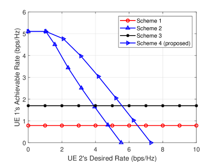
Fig. 2 shows UE1’s achievable rate (defined as in bits per second per Hertz (bps/Hz), where SINR denotes the maximum achievable SINR in each scheme) by different schemes versus UE2’s given rate, . The transmit power of BS2 is assumed to be identical to that of BS1, i.e., dBm. It is observed that the performance of schemes 2 and 4 decreases with increasing UE2’s rate or , since more transmit power needs to be allocated for transmitting UE2’s message by BS1 in order to cancel its (combined) interference at UE1 by SIC. In contrast, without the need of applying SIC at UE1’s receiver to cancel UE2’s interference, the performance of schemes 1 and 3 is observed to be unaffected by UE2’s rate. In addition, it is observed that the proposed scheme 4 significantly outperforms schemes 1 and 3 when UE2’s rate is not high. Moreover, the performance gap between schemes 2 and 4 is observed to be enlarged as UE2’s rate increases, which is consistent with our discussion at the end of Section III-A.
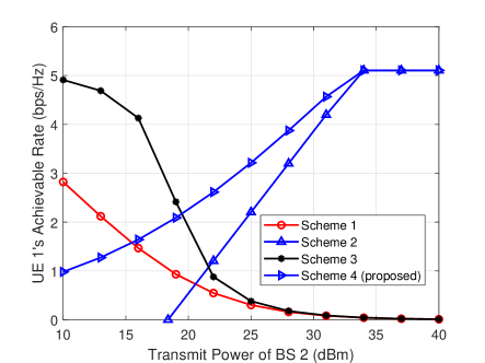
Next, we plot UE1’s achievable rate versus BS2’s transmit power in Fig. 3 by fixing bps/Hz. It is observed that UE1’s achievable rates by schemes 1 and 3 quickly diminish as increases, due to the increasing (residual) co-channel interference. In contrast, UE1’s achievable rates by schemes 2 and 4 increase with or the interference power and finally converge to the same maximum value when UE2’s rate can be satisfied even without BS2’s cooperation, i.e., , corresponding to the second case of (7) and (21). It is also observed that scheme 4 outperforms scheme 3 when or the interference power at UE1 is sufficiently large, as analytically shown in Section III-B.
V Conclusions
This letter proposes a new cooperative NOMA scheme for cellular downlink to resolve the strong asymmetric interference issue. The key difference from the conventional NOMA lies in the new superposition signal design for the purpose of enhancing the co-channel interference at the receiver to facilitate SIC. It is shown both analytically and numerically that the proposed scheme significantly outperforms the conventional NOMA with SIC (scheme 2) when the co-channel interference is comparable to the desired signal in power, as well as the existing interference transmission and cancellation (ITC) scheme without SIC (scheme 3)[8] when the co-channel interference is strong. Both scenarios may practically occur in cellular networks (e.g., for cellular-connected UAVs).
References
- [1] S. R. Islam, N. Avazov, O. A. Dobre, and K.-S. Kwak, “Power-domain non-orthogonal multiple access (NOMA) in 5G systems: Potentials and challenges,” IEEE Commun. Surveys Tuts., vol. 19, no. 2, pp. 721–742, 2nd Quart. 2017.
- [2] Z. Ding, X. Lei, G. K. Karagiannidis, R. Schober, J. Yuan, and V. K. Bhargava, “A survey on non-orthogonal multiple access for 5G networks: Research challenges and future trends,” IEEE J. Sel. Areas Commun., vol. 35, no. 10, pp. 2181–2195, Oct. 2017.
- [3] 3GPP-TR-36.859, “Study on downlink multiuser superposition transmission (MUST) for LTE,” 2015, 3GPP technical report. [Online]. Available: www.3gpp.org/dynareport/36859.htm
- [4] J. Choi, “Non-orthogonal multiple access in downlink coordinated two-point systems,” IEEE Commun. Lett., vol. 18, no. 2, pp. 313–316, Feb. 2014.
- [5] Y. Tian, A. R. Nix, and M. Beach, “On the performance of opportunistic NOMA in downlink CoMP networks,” IEEE Commun. Lett., vol. 20, no. 5, pp. 998–1001, May 2016.
- [6] M. S. Ali, E. Hossain, A. Al-Dweik, and D. I. Kim, “Downlink power allocation for CoMP-NOMA in multi-cell networks,” IEEE Trans. Commun., vol. 66, no. 9, pp. 3982–3998, Sep. 2018.
- [7] W. Shin, M. Vaezi, B. Lee, D. J. Love, J. Lee, and H. V. Poor, “Coordinated beamforming for multi-cell MIMO-NOMA,” IEEE Commun. Lett., vol. 21, no. 1, pp. 84–87, Jan. 2016.
- [8] W. Mei and R. Zhang, “Cooperative downlink interference transmission and cancellation for cellular-connected UAV: A divide-and-conquer approach,” IEEE Trans. Commun., to be published. [Online]. Available: https://arxiv.org/pdf/1906.00220.pdf
- [9] 3GPP-TR-36.777, “Study on enhanced LTE support for aerial vehicles,” 2017, 3GPP technical report. [Online]. Available: www.3gpp.org/dynareport/36777.htm
- [10] W. Mei and R. Zhang, “Uplink cooperative NOMA for cellular-connected UAV,” IEEE J. Sel. Topics Signal Process., vol. 13, no. 3, pp. 644–656, Jun. 2019.
- [11] L. Liu, S. Zhang, and R. Zhang, “Multi-beam UAV communication in cellular uplink: Cooperative interference cancellation and sum-rate maximization,” IEEE Trans. Wireless Commun., vol. 18, no. 10, pp. 4679–4691, Oct. 2019.
- [12] W. Mei, Q. Wu, and R. Zhang, “Cellular-connected UAV: uplink association, power control and interference coordination,” IEEE Trans. Wireless Commun., vol. 18, no. 11, pp. 5380–5393, Nov. 2019.
- [13] E. Dahlman, S. Parkvall, and J. Skold, 4G: LTE/LTE-advanced for mobile broadband. Oxford, UK: Academic press, 2013.