The Detectors of the Mu2e Experiment
Abstract
The Mu2e experiment aims to test Charge Lepton Flavour Violation to an unprecedented level, enhancing the current sensitivity by four orders of magnitude for the neutrinoless conversion of muons into electrons. A series of graded solenoids convey an intense, pulsed muon beam to an aluminum target. The main detector components are a low mass straw drift tubes tracker, a pure Cesium Iodide calorimeter and an extruded plastic scintillator cosmic ray veto. Requirements, tests on prototypes and status of the production will be discussed.
1 The Mu2e Experiment
The Mu2e experiment [1] at Fermilab will search for the charged-lepton flavor violating neutrino-less coherent conversion of a negatively charged muon into an electron in the field of an aluminum nucleus. The process produces a mono-energetic electron with an energy slightly below the muon rest mass (104.967 MeV). If no events are observed, Mu2e will set a limit on the ratio between the conversion rate and the muon capture rate of (@ 90 C.L.). This will improve the current limit [2] by four orders of magnitude. On the other hand, an observation of Charge Lepton Flavour Violation (CLFV) events will provide a clear indication of New Physics (NP) beyond the Standard Model up to mass scales of nearly TeV, far beyond the direct search reach at colliders, complementing and extending other CLFV searches on a wide range of NP scenarios [3].
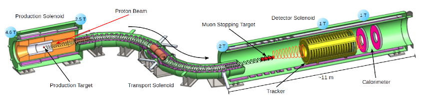
The Mu2e design is based on the MELC concept [4]. An intense pulsed muon beam (sec) is produced by 8 GeV, 8 kW protons hitting a tungsten target and it is stopped on an aluminum target after travelling inside a very long, curved series of solenoids (Fig. 1). The strong negative gradient of the Production Solenoid, from 4 to 2.5 T, confines soft pions and increases the yield through magnetic reflection. The S-shaped Transport Solenoid efficiently transfers low energy, negatively charged particles while allowing a large fraction of pions to decay into muons. The Detector Solenoid has a graded field from 2 to 1 Tesla in the upstream region of the stopping target to increase acceptance for Conversion Electron (CE) events.
The Mu2e detector, just downstream of the aluminum target inside a 1T solenoid, is composed of a tracker and an electromagnetic calorimeter. The Mu2e tracker measures the momentum of the conversion electron and separates it from the background. The crystal calorimeter plays an important role in providing particle identification capabilities and a fast online trigger filter, while also aiding the track reconstruction capabilities. The detector solenoid is in vacuum, at Torr, and in a high radiation environment. The entire detector region and part of the transport solenoid are surrounded by a Cosmic Ray Veto (CRV) that reduces the cosmic ray background. A High Purity Germanium Detector and a Lanthanum Bromide crystal constitute the Stopping Target Monitor, placed m after the stopping target, which provides normalization to CLFV events by detecting -rays emitted from muon capture in the aluminum target.
In order to reach the required sensitivity, control of the background to the level of less than 0.5 expected events is required. The background coming from the beam is reduced by means of a pulsed beam structure with a proton extinction lower than 10-10: a delay in the start of the live window of 700 ns after the bunch arrival time removes the prompt background from the acquired data. The extinction level is monitored by detecting scattered protons from the production target to evaluate the fraction of out-of-time beam.
2 The tracking system
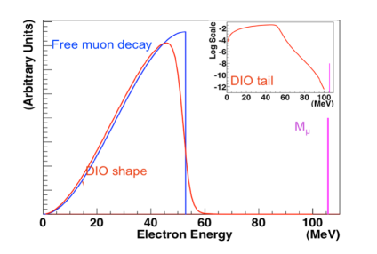
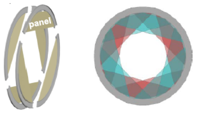
The Mu2e tracker system [5] is designed to maximize acceptance for conversion electrons while minimizing the contamination from the muon Decay-In-Orbit (DIO) background, where nuclear modifications push the DIO spectrum towards the CE signal (Fig. 2 left). Energy loss and detector resolution produce an overlap of the two processes. The selected design is based on nearly 20,000 low mass straw drift tubes of 5 mm in diameter, with a 15 m Mylar wall and 25 m sense wire. Straws of lengths ranging from 430 to 1220 mm are oriented transversely to the solenoid axis and arranged in 18 stations (Fig. 2 right), for a total length of 3.2 metres along the solenoid axis. A central hole, 38 cm in diameter, makes the device blind to low momentum background particles ( MeV/c) which are constrained to low radius by the solenoidal field.
 |
 |
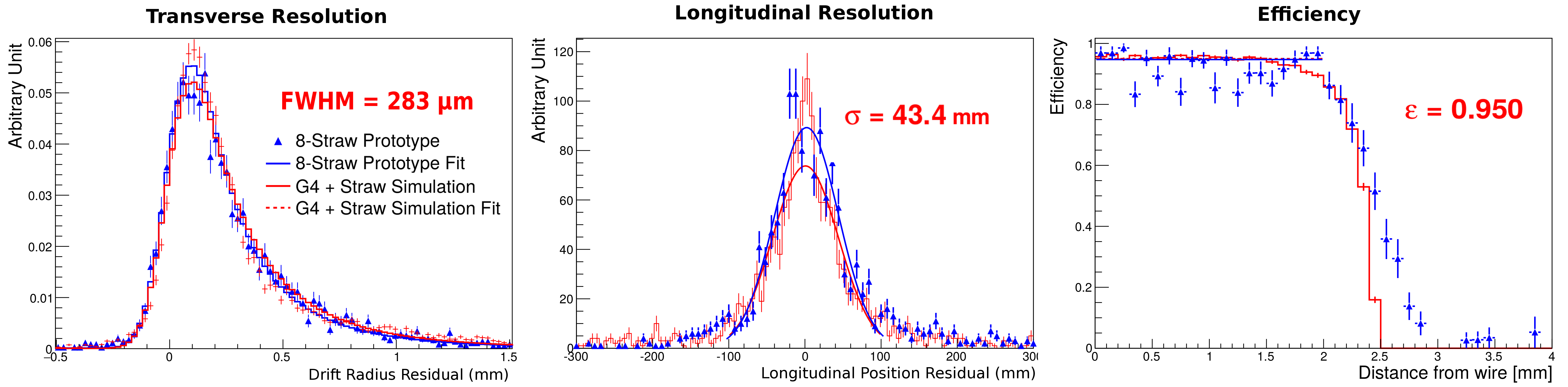
An eight channel tracker prototype was built and tested with cosmics rays to measure performances and tune detector simulations. In Fig. 3, the position resolution and straw efficiency are compared with Monte Carlo expectations. Good reproducibility of data is observed.
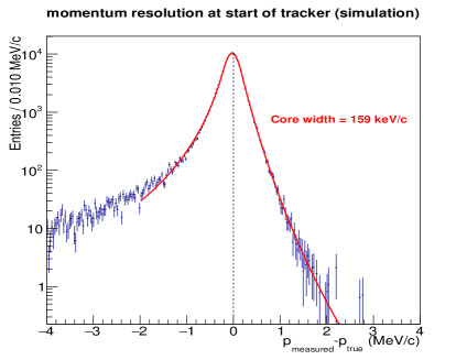
The tracker performance is studied with Monte Carlo using the full Mu2e simulation. Results are reported in Fig. 4. The core momentum resolution of 159 keV/c is well within physics requirements and stable when increasing accidental hit rate. The total track efficiency of is fully dominated by geometric acceptance.
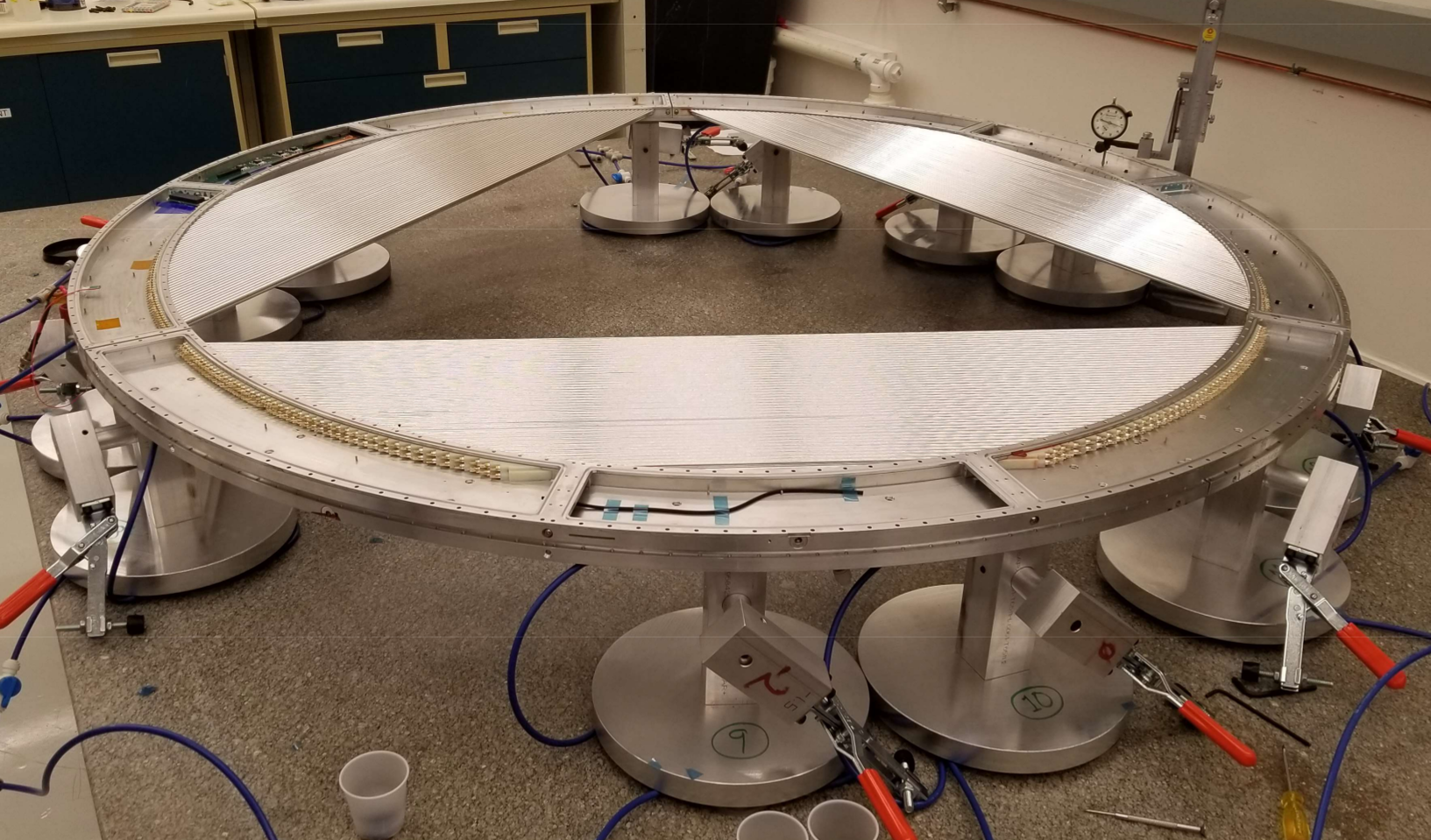
At the moment of writing, twelve pre-production panels are under construction and testing. In Fig. 5, three panels are assembled to form a tracking plane. A vertical slice test on fully instrumented panels with the entire Front-End Electronics chain will be performed.
3 The calorimeter system
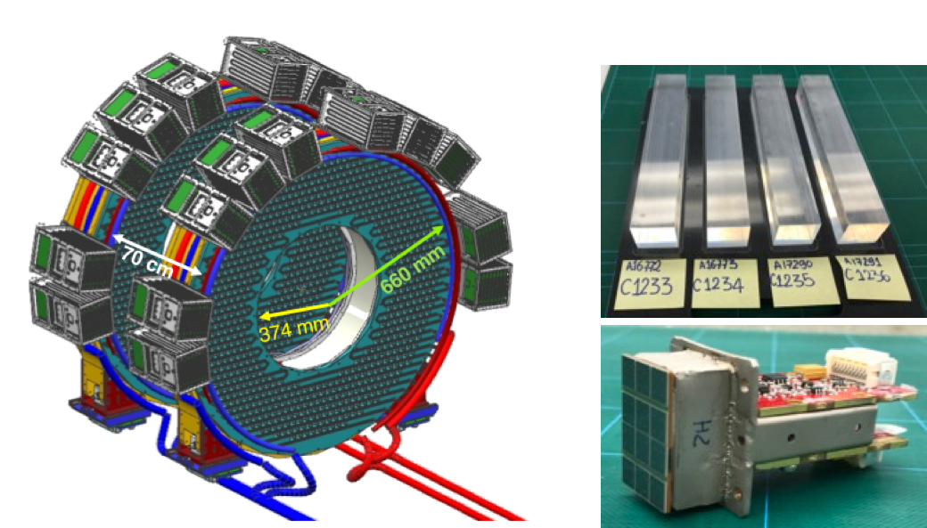
The Mu2e calorimeter [6] has to provide confirmation for CE signal events, a powerful separation - with a muon rejection factor of , a standalone trigger and seeding for track reconstruction. An energy resolution of ) and a time resolution of ps for 100 MeV electrons are sufficient to fulfil these requirements. The calorimeter design consists of two disks made from 674 undoped CsI scintillating crystals with () mm3 dimension. Each crystal is read-out by two custom array large area ( of mm2 cells) UV-extended Silicon Photo-Multipliers (SiPMs). Each SiPM is connected to a Front-End Electronics (FEE) board providing amplification and shaping of the signal. Groups of 20 signals are sent to a custom digitizer module (DIRAC, DIgitizer and ReAdout Controller) where they are sampled at 200 Mega samples per second and transferred to the Mu2e data acquisition system. A radioactive source and a laser system allow setting the energy scale and monitor the fast changes of response and resolution. The crystals will receive an ionizing dose of 90 krad and a fluence of n/cm2. The photosensors, being shielded by the crystals, will get a three times smaller dose. The layout of the calorimeter system and pictures of crystals and a readout channel are shown in Fig. 6.
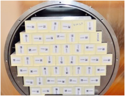
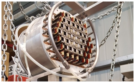
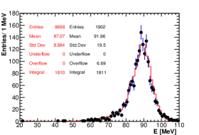
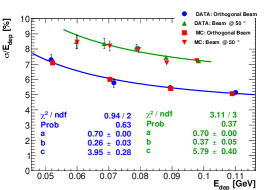
A long R&D phase with small prototypes demonstrates that the calorimeter design easily satisfies the requirements [7, 8, 9, 10]. Pre-production components have been used to build a large size calorimeter prototype, Module-0 (Fig. 7), with 51 crystals and 102 SiPMs and front end boards [11]. It represents a portion of the final disk and has been used to test the integration and assembly procedures and to evaluate the operations of running in vacuum and at low temperatures. Module-0 performance was tested with an electron beam of 60-120 MeV at the INFN Beam Test Facility in Frascati [12]. The energy distribution for 100 MeV electrons is well reproduced by the calorimeter simulation, Fig. 8 left. Energy and time resolution are evaluated with particles impinging on the calorimeter surface both at 0 and 50 degrees. The latter is the expected incidence angle for conversion electrons in Mu2e. An energy resolution of 5% (7%) and a time resolution of 120 ps (150 ps) are obtained for 100 MeV particles impinging at (), Fig. 8 center and right. Results satisfy physics requirements and are well reproduced by simulation.
 |
 |
 |
 |
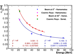 |
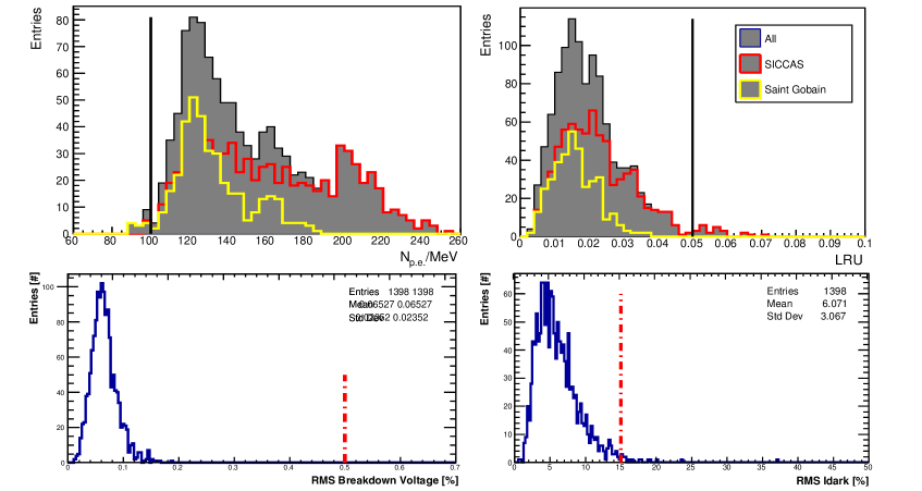
The complete production components for SiPMs and 85% of production crystals have been received and characterized. For all of the 4000 sensors, the breakdown voltage and the dark current are measured at different temperatures. The spread of these quantities over the six cells of each sensor is used as quality control parameter (Fig. 9 bottom). The overall rejection factor is 1.2%, dominated by those sensors whose dark current RMS is too large. The Quality Control of CsI crystals foresees a dimensional control, with 0.1 mm tolerance with respect to nominal values, and a measurement of the optical properties [13]. In Fig. 9 (top) the number of photoelectrons and the uniformity response along the crystals are reported for both of the CsI producers. About 10% of the crystals have been rejected, mostly due to problems with mechanical tolerances. Irradiation tests have been carried out for small CsI and SiPM production subsamples. Results show that the calorimeter will be able to operate at the end of the Mu2e lifetime at a temperature below C. Mean Time To Failure tests on photosensors demonstrate an MTTF value 10 times larger than the experiment needs.
The prototypes of FEE and DIRAC have been exposed to a large ionization dose and neutron fluence to qualify rad-hard components. A slice test with the whole calorimeter electronic chain provides results comparable to those achieved using a commercial digitizer. A DIRAC prototype is currently used to read 16 channels of Module-0.
4 Cosmic Ray Veto
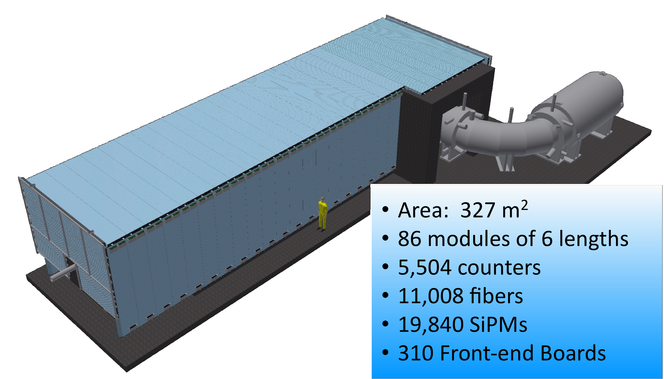
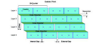
In absence of the vetoing system, cosmic ray muons interacting with the detector materials produce false signal CE candidates at a rate of approximately one/day. In order to maintain the background under the required level, the CRV has to provide a vetoing efficiency of at least 99.99% for cosmic ray tracks while withstanding an intense radiation environment. The Cosmic Ray Veto system [14] is made by four staggered layers of extruded plastic scintillation counters with two embedded 1.4 mm diameter Wavelength Shifting Fibers/counter, alternated with absorber slabs (Fig. 10). Each fiber is readout by means of 22 mm2 SiPMs. To achieve the required coverage, a total of 5,504 counters are needed, organized in 86 modules of six different lengths for a total surface coverage of 327 m2.
 |
 |
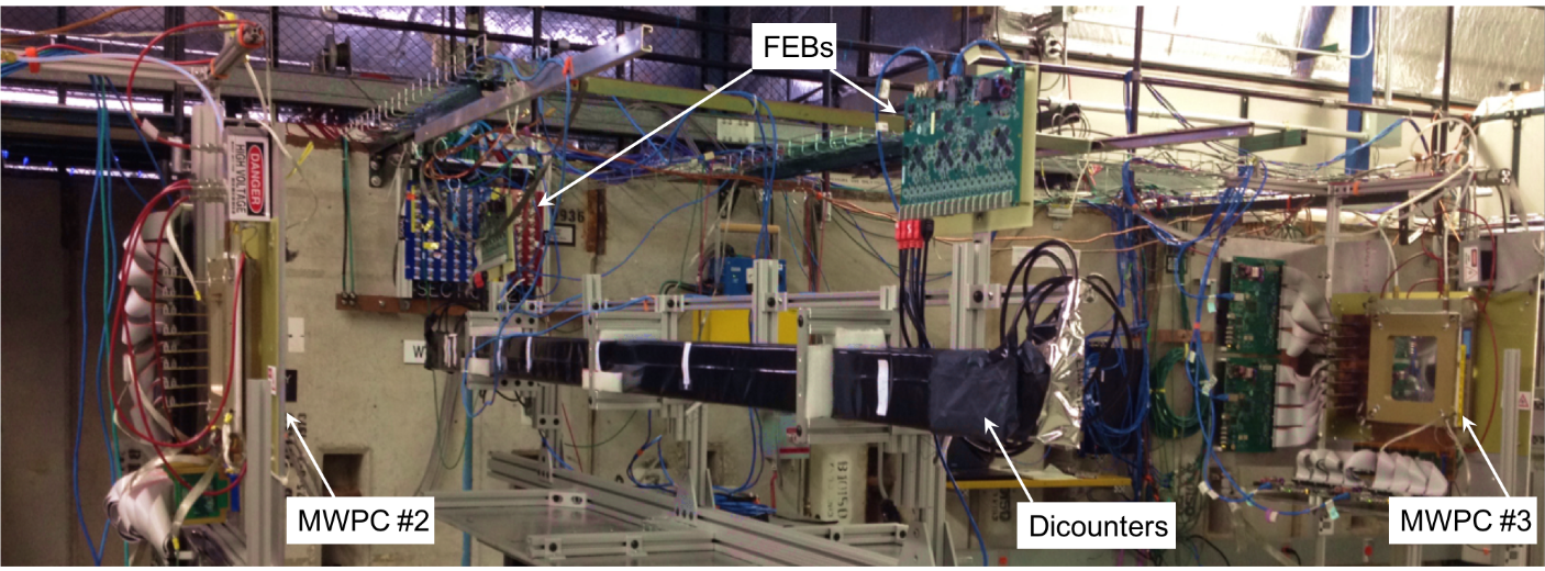
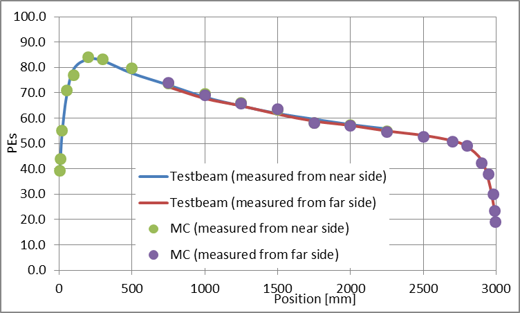
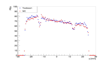
Measurements on a full size prototype with 120 GeV protons in the Fermilab test beam area was carried out (Fig. 11) demonstrating that the needed light yield can be reached: the number of photo-eletrons obtained at 1 meter from the readout end provides a safety factor of with respect to the requirements [15]. In Fig. 12 test beam results are compared with the results obtained from the CRV counter simulation, which includes scintillation and Cerenkov photon production/transport, SiPM and electronics responses. Good agreement is obtained after tuning the Monte Carlo parameters. Irradiation of CRV SiPMs with neutrons was also tested to understand the maximum level of fluence acceptable for operations [16]: neutrons could deteriorate the sensors response and increase the detector occupancy and dead-time so that shielding is mandatory.
 |
 |
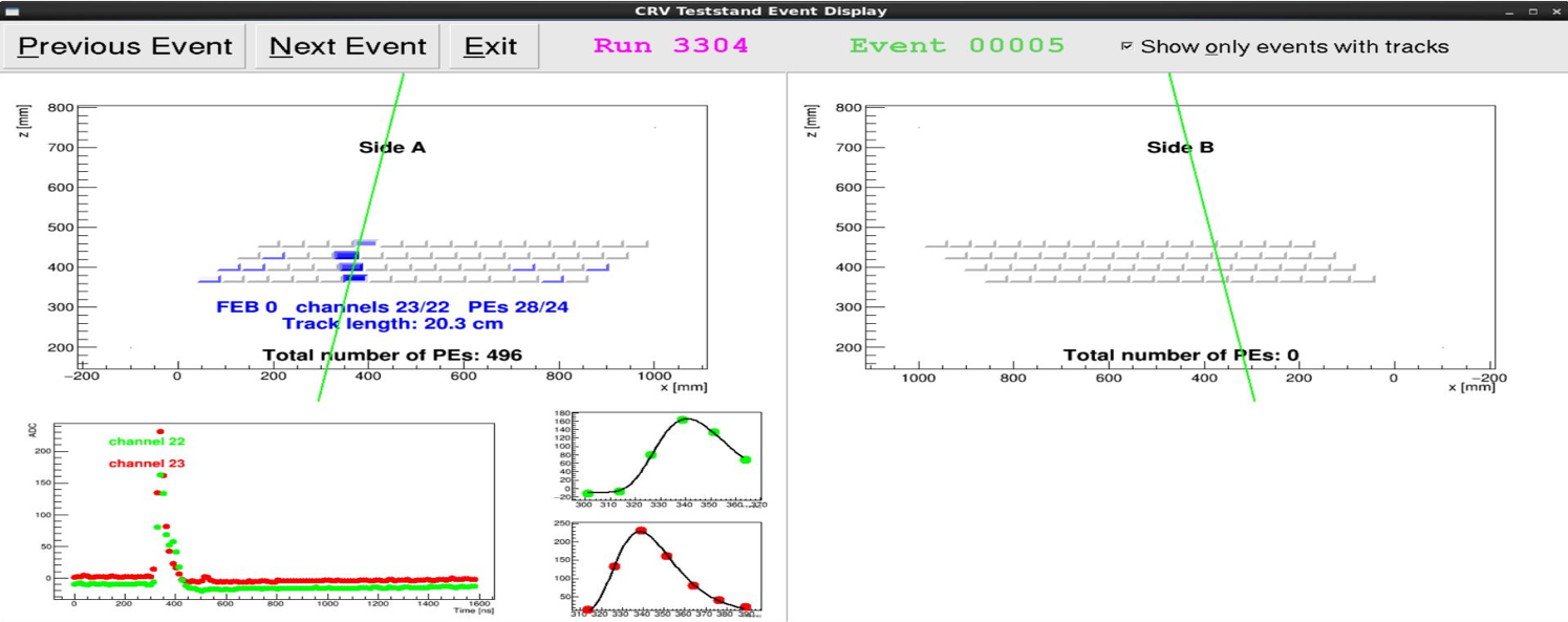
The assembly of CRV di-counters started in June 2018 and about half of them have been produced. Production of photosensors and electronics are also underway and 6% of the modules have been assembled. A test stand with cosmic rays is used to control the modules after production. An example of a cosmic ray event, as recorded by the test stand and by the CRV module under test, is shown in Fig. 13.
5 Conclusions and perspectives
The Mu2e experiment will exploit the world’s highest intensity muon beams of the Fermilab Muon Campus to search for CLFV, improving current sensitivity by a factor and with a discovery capability over a wide range of New Physics models. A low mass straw tube tracker, a pure CsI crystal calorimeter with SiPM readout and a high efficiency cosmic ray veto have been selected to satisfy the demanding requirements. Tests on prototypes and pre-production modules meet the experimental needs. Detector construction is in progress and is expected to be completed by the end of 2020. Installation will begin in 2021, followed by commissioning, with data beginning in late 2023.
Acknowledgments
We are grateful for the vital contributions of the Fermilab staff and the technical staff of the participating institutions. This work was supported by the US Department of Energy; the Istituto Nazionale di Fisica Nucleare, Italy; the Science and Technology Facilities Council, UK; the Ministry of Education and Science, Russian Federation; the National Science Foundation, USA; the Thousand Talents Plan, China; the Helmholtz Association, Germany; and the EU Horizon 2020 Research and Innovation Program under the Marie Sklodowska-Curie Grant Agreement No. 690835 and 734303. This document was prepared by members of the Mu2e Collaboration using the resources of the Fermi National Accelerator Laboratory (Fermilab), a U.S. Department of Energy, Office of Science, HEP User Facility. Fermilab is managed by Fermi Research Alliance, LLC (FRA), acting under Contract No. DE-AC02-07CH11359.
References
- [1] L. Bartoszek et al., “Mu2e Technical Design Report”, arXiv:1501.05241, Fermilab-TM-2594, Fermilab-Design-2014-01.
- [2] W.H. Bertl et al., SINDRUM II Collaboration, “A search for – conversion in muonic gold”, Eur. Phys. J. C 47 (2006) 337.
- [3] A. de Gouva and P. Vogel, “Lepton flavor and number conservation, and physics beyond the standard model”, Progress in Particle and Nuclear Physics 71 (2013) 75.
- [4] R. Dzhilkibaev and V. Lobashev, “On the Search for Conversion on Nuclei”, Sov. J. Nucl. Phys. 49 (1989) 384
- [5] M.J. Lee on behalf of the Mu2e collaboration, “The Straw-tube Tracker for the Mu2e Experiment”, Nuclear and Particle Physics Proceedings 273-275 (2016) 2530.
- [6] N. Atanov et al., “The Mu2e Calorimeter Final Technical Design Report”, arXiv:1802.06341 (2018).
- [7] N. Atanov et al., “Energy and time resolution of a LYSO matrix prototype for the Mu2e experiment”, Nucl. Instrum. Meth. A 824 (2016) 684.
- [8] N. Atanov et al., “Measurement of time resolution of the Mu2e LYSO calorimeter prototype”, Nucl. Instrum. Meth. A 812 (2016) 104.
- [9] N.Atanov et al., “Design and status of the Mu2e electromagnetic calorimeter”, Nucl. Instr. Meth. A 824 (2016) 695.
- [10] O. Atanova et al., “Measurement of the energy and time resolution of a undoped CsI + MPPC array for the Mu2e experiment”, JINST 12 (2017) P05007, arXiv:1702.03720.
- [11] N. Atanov et al., “Design and status of the Mu2e crystal calorimeter”, IEEE-TNS 65 (2018) 2073, arXiv:1802.06346.
- [12] G. Mazzitelli et al., “Commissioning of the DANE beam test facility ”, Nucl. Instr. Meth. A 515 (2003) 524.
- [13] N. Atanov et al., “Quality Assurance on Undoped CsI Crystals for the Mu2e Experiment”, IEEE 65 (2018) 752.
- [14] A. Artikov et al., “Performance of Scintillator Counters with Silicon Photomultiplier Readout”, arXiv:1511.00374 (2015).
- [15] A. Artikov et al., “Photoelectron Yields of Scintillation Counters with Embedded Wavelength-Shifting Fibers Read Out With Silicon Photomultipliers”, Nucl. Instr. Meth. A 890 (2018) 84, arXiv:1709.06587.
- [16] G. Blazey et al., “Radiation Tests of Hamamatsu Multi-Pixel Photon Counters”, Nucl. Instr. Meth. A. 927 (2019) 463.