Scattering of Dirac electrons from a skyrmion: emergence of robust skew scattering
Abstract
We study electron scattering from a closed magnetic structure embedded in the top surface of a topological insulator (TI). Outside of the structure there is a uniform layer of ferromagnetic insulator (FMI), leading to a positive effective mass for the Dirac electrons. The mass inside the structure can be engineered to be negative, leading to a skyrmion structure. The geometric shape of the structure can be circular or deformed, leading to integrable or chaotic dynamics, respectively, in the classical limit. For a circular structure, the relativistic quantum scattering characteristics can be calculated analytically. For a deformed structure, we develop an efficient numerical method, the multiple multipole method, to solve the scattering wavefunctions. We find that, for scattering from a skyrmion, anomalous Hall effect as characterized by strong skew scattering can arise, which is robust against structural deformation due to the emergence of resonant modes. In the short (long) wavelength regime, the resonant modes manifest themselves as confined vortices (excited edge states). The origin of the resonant states is the spin phase factor of massive Dirac electrons at the skyrmion boundary. Further, in the short wavelength regime, for a circular skyrmion, a large number of angular momentum channels contribute to the resonant modes. In this regime, in principle, classical dynamics are relevant, but we find that geometric deformations, even those as severe as leading to fully developed chaos, have little effect on the resonant modes. The vortex structure of the resonant states makes it possible to electrically “charge” the skyrmion, rendering feasible to manipulate its motion electrically. In the long wavelength regime, only the lowest angular momentum channels contribute to the resonant modes, making the skew scattering sharply directional. These phenomena can be exploited for applications in generating dynamic skyrmions for information storage and in Hall devices.
I Introduction
This paper is devoted to studying relativistic quantum scattering of Dirac electrons in systems involving magnetism. There are two motivations. Firstly, quantum scattering of spin-1/2 fermions is fundamental to developing two-dimensional (2D) Dirac material based devices. Secondly, magnetic materials have been efficient carriers of information and the physics of magnetic textures has been a topic of significant interest. In general, in quantum scattering, the nature of the underlying classical dynamics can play a role. For example, consider electronic scattering from a 2D electrical potential domain generated by an external gate voltage. In the classical limit of zero wavelength, the electrons are point particles and the domain is effectively a 2D billiard system in which electrons move along straight lines and are reflected when “hitting” the boundary. For a circular domain, the classical dynamics are integrable. However, for a deformed domain, e.g., a stadium shaped domain, the classical dynamics can be ergodic in the phase space. In this case, there is sensitive dependence on initial condition because two nearby trajectories will diverge from each other exponentially - the hallmark of chaos. Since geometric deformations are inevitable in applications, it is necessary in the study of quantum scattering to take into account the nature of classical dynamics. Especially, it is useful to consider deformed domains to uncover the possible effects of classical chaos on quantum scattering.
We employ the setting of a two-dimensional (2D), closed magnetic structure embedded in a uniform layer of ferromagnetic insulating (FMI) materials on the top of a 3D topological insulator (TI). Outside of the structure, due to the FMI layer and the proximity effect, the electrons obey the Dirac equation with a positive mass. The mass of the closed structure can be engineered to be negative, making it a skyrmion Nagaosa and Tokura (2013); Fert et al. (2013); Everschor-Sitte et al. (2018); Ochoa and Tserkovnyak (2018). The skyrmion structure can be deformed so that the classical particle motions inside are chaotic. The massive Dirac electrons moving on the surface of the TI are scattered by the structure. The system thus not only provides a setting for exploring new physics associated with scattering of Dirac electrons from a magnetic skyrmion for applications (e.g., in spintronics), but also represents a paradigm to study the effects of classical chaos on relativistic quantum scattering in the presence of magnetism.
To be systematic and general, we consider the cases where the magnetic structure on the top of TI can be of either the skyrmion or the non-skyrmion type. The structure can simply be a circle, in which case the classical dynamics are integrable, or it can be deformed from the circular shape, e.g., a stadium, where there is fully developed chaos in the classical limit. For a circular structure, the various scattering cross sections can be obtained analytically from the standard partial wave analysis. For a deformed structure, we adopt an efficient method, the multiple multipole (MMP) method in optics, to solving the scattering wavefunctions of the two-component Dirac fermion in the magnetic system. We focus on two regimes: the short wavelength regime where the size of the magnetic structure is larger than the wavelength so that the underlying classical dynamics are relevant, and the long wavelength regime where the structure size is comparable or smaller than the wavelength. There are two main results. Firstly, a skyrmion can lead to strong skew scattering due to the emergence of resonant modes that manifest themselves as confined vortices inside the skyrmion in the short wavelength regime or confined edge states in the long wavelength regime. The resonant modes are the result of mass sign change across the skyrmion boundary. For a circular skyrmion, in the short wavelength regime, a large number of angular momentum channels contribute to the resonant modes and electron charging arises, providing a way to electrically manipulate the skyrmion motion. In the long wavelength regime, only the lowest angular momentum channels contribute to the resonant states, leading to strongly directional skew scattering with implications in developing Hall devices. The second result is that classical chaos generated by geometrical deformations has little effect on the scattering from a skyrmion. The scattering phenomena uncovered for the circular case are thus robust. The immunity of the scattering dynamics to severe deformation of the skyrmion structure is advantageous for spintronic device applications.
This paper is organized as follows. In Sec. II, we provide the background of our research in terms of magnetic skyrmion, TIs, the “marriage” between skyrmion and TI, and relativistic quantum chaos. In Sec. III, we describe the Hamiltonian and outline the methods (analytic and numerical). In Sec. IV, we demonstrate the emergence of robust resonant states in scattering from skyrmion for both integrable and chaotic classical dynamics. In Sec. V, we develop a partial-wave decomposition based analysis for resonances associated with scattering corresponding to classical integrable dynamics. In Sec. VI, we summarize the main findings and discuss experimental feasibility and open issues. Finally, in Appendix, we detail the developed MMP method for numerically calculating the scattering wave functions associated with deformed domain hosting chaotic dynamics in the classical limit.
II Background
Magnetic skyrmion.
Generally, a skyrmion is a particle-like magnetic excitation with a swirling topological 2D spin texture, i.e., the spin at the core and the spin at the perimeter point are in opposite directions Nagaosa and Tokura (2013); Fert et al. (2013); Everschor-Sitte et al. (2018); Ochoa and Tserkovnyak (2018). The small size of the skyrmions and the possibility of moving them with electrical currents of small density (A/m2) make them promising candidates for spintronic storage or logic devices Nagaosa and Tokura (2013); Fert et al. (2013). Skyrmions have been experimentally observed in chiral magnets Mühlbauer et al. (2009); Yu et al. (2010) as a result of the competition between the Dzyaloshiskii-Moriya (DM) interactions, Heisenberg exchange, and Zeeman interactions. It has been demonstrated that metallic skyrmions can be driven by spin transfer torque (STT) from the electric current Jonietz et al. (2010); Zang et al. (2011); Yu et al. (2012). Optical skyrmion lattices have been achieved in an evanescent electromagnetic field Tsesses et al. (2018). In addition, the topological spin Hall effect has been demonstrated in which a pure transverse spin current is generated from a skyrmion spin texture Yin et al. (2015); Denisov et al. (2016, 2017); Ndiaye et al. (2017a); Denisov et al. (2018).
Topological insulators.
TIs are quantum materials with surface states residing in the bulk insulating gap Hasan and Kane (2010); Qi and Zhang (2011). The edge states are topologically protected and are robust against nonmagnetic disorders due to a strong spin-momentum locking. The electron motions on the surface follow the 2D linear dispersion with a single band-touching Dirac point and are described by the Dirac equation. In spite of the strong spin-momentum locking, the surface electronic states are sensitive to magnetic perturbations. That is, the electrons will be scattered off upon encountering a magnetic structure on the surface of the TI. The interaction between the topological surface states and magnetic materials in a quasi-one dimensional setting has been studied Tserkovnyak and Loss (2012); Wei et al. (2013); Katmis et al. (2016) where, due to the spin-momentum locking, the exchange coupling between the magnetization and the surface electronic states can lead to intriguing phenomena such as anomalous magnetoresistance and unconventional transport behaviors Yokoyama et al. (2010a); Wu et al. (2010). The interaction can also lead to nonlinear or even chaotic dynamics in the evolution of magnetization of the FMI Wang et al. (2016, 2018a). For example, complicated dynamics can emerge in the magnetization switching due to a Hall-current-induced effective anisotropic field Garate and Franz (2010); Yokoyama et al. (2010b); Yokoyama (2011); Tserkovnyak and Loss (2012) and steady self-oscillations can arise in an FMI/TI heterostructure Semenov et al. (2014); Duan et al. (2015); Ndiaye et al. (2017b). A quite recent computational study has revealed phase locking in the magnetization dynamics of two FMIs on the top of a 3D TI Wang et al. (2018b).
Skyrmion and TI.
Efforts in improving thermal efficiency and better manipulating skyrmions have led to the “marriage” between skyrmion and TI, where skyrmions arise on the surface of a TI. Electric charging of magnetic vortices on the surface of a TI was investigated Nomura and Nagaosa (2010), and the confinement state in the skyrmion structure on the surface of a TI was discovered, paving the way to driving skyrmion motion using an applied electric field Hurst et al. (2015). Electron skew scattering induced by the skyrmion structure on the TI surface was also studied Araki and Nomura (2017). Quite recently, the combination of two skyrmions with opposite winding numbers, called skyrmionum in an FMI/TI heterostructure was observed in the physical space Zhang et al. (2016); Pylypovskyi et al. (2018); Göbel et al. (2019). Theoretically, fluctuation-induced Néel and Bloch skyrmions on the surface of a TI have been predicted Nogueira et al. (2018).
Previous studies focused on scattering of electrons from radially symmetric skyrmion structures. Deformed skyrmion structure has been studied in recent years. For example, it was found that Majorana modes are robust against skyrmion deformations Garnier et al. (2019). Quantum engineering of Majorana fermions in deformed skyrmion structure was also studied Rachel et al. (2017); Mascot et al. (2018) and deformed (elongated) skyrmions were used for stabilization and control of Majorana bound states in proximity to an s-wave superconductor Güngördü et al. (2018). Shape dependent resonant modes have been discovered recently in skyrmions in magnetic nanodisks Liu et al. (2018).
Relativistic quantum chaos.
The study of the manifestations of classical chaos in relativistic quantum systems was pioneered by Sir Michael Berry and his collaborator Berry and Mondragon (1987) and recently emerged as an interdisciplinary field of research Lai et al. (2018); Huang et al. (2018) with applications to Dirac material systems Neto and Novoselov (2011); Ajayan et al. (2016). In contrast to the traditional field of (nonrelativistic) quantum chaos Stöckmann (2006); Haake (2010) where classical chaos often bears strong signatures in the corresponding quantum systems, such “fingerprints” tend to be weakened in the relativistic quantum counterparts Xu and Lai (2019); Han et al. (2019). For example, in scattering (e.g., electronic transport through a quantum dot structure), chaos tends to smooth out fluctuations in scattering matrix elements, quantum transmission, or conductance Blümel and Smilansky (1988); Jalabert. et al. (1990); Lai et al. (1992); Marcus et al. (1992); Ketzmerick (1996); Yang et al. (2012) if the quantum behaviors are governed by the Schrödinger equation. However, in two-dimensional (2D) Dirac materials such as graphene, strong fluctuations of the quantum scattering characteristics can persist to certain extent in spite of classical chaos Yang et al. (2011); Ying et al. (2012). Another example is a 2D deformed ring with a line of magnetic flux through the center, where Schrödinger electrons are localized but Dirac electrons can keep circulating along the edges of the ring domain, generating a superpersistent current in spite of fully developed classical chaos in the domain Xu et al. (2015a) - a phenomenon that can be exploited for creating a robust relativistic qubit Xu et al. (2015b). Quite recently, the weakening of the manifestations of chaos in spin-1/2 Dirac fermion systems was studied Han et al. (2019) using the approach of out-of-time-ordered correlator Larkin and Ovchinnikov (1969). It has also been revealed that, for scattering in spin-1 Dirac-Weyl fermion systems, a class of robust resonant modes can emerge that defy classical chaos completely Xu and Lai (2019).
III Model and method
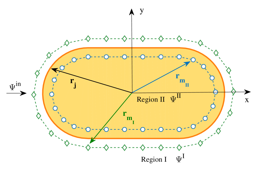
We place an FMI thin film (e.g., Cu2OSeO3) on the top of a TI with a single magnetic structure at the center of the thin film, as schematically illustrated in Fig. 1. The motions of the surface electrons are affected by the structure with the magnetization vector . The Hamiltonian of the system is
| (1) |
where is the Fermi velocity, is the momentum operator, are the Pauli matrices, and is the spin-splitting energy from the exchange interaction between the electron and the magnetization. In the polar coordinates , for a circular structure, the magnetization vector can be parameterized as
| (2) |
For a deformed magnetic structure, there is swirling spin texture with magnetic moment points up on the edge and down in the center Schütte and Garst (2014). The out-of-plane component of the magnetic texture acts as a Dirac mass term, which opens a gap in the electronic band structure. The in-plane component can lead to an emergent magnetic field in the form
For a swirling skyrmion structure, the emergent magnetic field is zero and the in-plane component can be gauged away Hurst et al. (2015); Araki and Nomura (2017). In this case, the “hard-wall” approximation can be invoked Hurst et al. (2015); Araki and Nomura (2017), with the point inside and outside of the skyrmion structure taking on the value of minus one and one (, ), respectively. In experiments, such a structure can be realized using materials with a strong out-of-plane magnetic anisotropy. In our study, we assume that the magnetic structure is fixed and unaffected by the interface electrons. Experimentally, a skyrmion structure can be stabilized via the Dzyaloshinskii-Moriya (DM) interaction in the FMI Nagaosa and Tokura (2013); Fert et al. (2013), where the skyrmion size depends on materials parameters such as the relative strength of the Heisenberg and DM exchange interactions Nagaosa and Tokura (2013); Fert et al. (2013). Our model is valid for skyrmion with a vortical magnetic texture as described. However, for hedgehog skyrmions, the in-plane magnetic field cannot be gauged away due to the emergent magnetic flux and the structure is not as stable as vortical skyrmions Nagaosa and Tokura (2013); Fert et al. (2013).
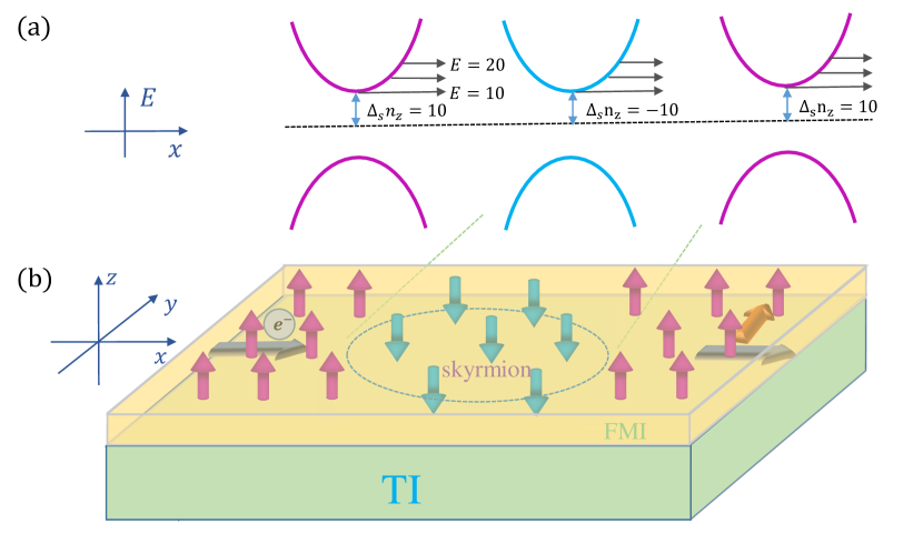
The energy-momentum dispersion for electrons in free space with a uniform magnetic texture (constant mass) is given by
| (3) |
as shown in Fig. 1(a). While the energy dispersion curve inside of the skyrmion appears similar to that outside of skyrmion, the spin direction is different for the electronic state due to the opposite signs of mass. An electron will then go through a scattering process in this 2D system. Because of the breaking of the time reversal symmetry, skew scattering will arise.
For a circular magnetic structure, the scattering wavefunction and the related behavior can be solved analytically using the partial-wave decomposition method (Sec. V). For a deformed skyrmion, analytic solutions of the scattering wavefunction are not feasible. We have developed an MMP based method, which has its origin in optics Leviatan and Boag (1987); Imhof (1996); Kaklamani and Anastassiu (2002); Moreno et al. (2002); Tayeb and Enoch (2004) and has recently been extended to scattering of pseudospin-1 particles Xu and Lai (2019). The basic idea is to assume two sets of fictitious poles along and in the vicinity of the entire boundary of the magnetic structure: one outside and another inside of the boundary. Each pole emits a wave in the form of Hankel function (spherical wave in the far field). The transmitted wavefunction at each point inside of the scatterer can be expressed as the superposition of the waves emitted by the poles outside of the scatterer. Similarly, the refracted wavefunction at each point outside of the scatterer can be written as the combination of the waves emitted by the poles inside of the scatterer. The incident plane wave as well as the reflected and transmitted waves are matched on the boundary to enable the poles to be determined, and the expansion coefficients can be obtained by solving the matrix eigenfunctions. (The details of the MMP method adopted to scattering from a magnetic structure are given in Appendix) We validate the method by comparing the MMP solutions with the analytic solution based on partial wave expansion for a circular skyrmion. Overall, the MMP method is effective and efficient for solving both the near- and far-field scattering problem for a magnetic scatterer of arbitrary shape.
In our calculation, we use the dimensionless quantity obtained via considerations of the scales of the physical quantities involved. In particular, the energy scale in the FMI/TI heterostructure is on the order of meV. In free space with zero mass, the wavevector corresponding to the energy of meV is . We take the dimensionless radius of the magnetic structure (circular shape) to be , which corresponds to a real structure of size of nm. We then set the dimensionless energy corresponding to meV to be . For , the corresponding energy gap is meV.
IV Emergence of robust resonant states in scattering from skyrmion
IV.1 Short wavelength regime - resonant vortices and edge modes
We concentrate on regime where the wavelength of the incoming Dirac electron is smaller than the size of the magnetic structure so that the classical dynamics inside the structure are relevant. We consider a circular structure as well as a deformed structure that leads to chaos in the classical limit to identify any effect of chaos on the electron scattering behavior.
Far-field behavior. Far away from the scattering center, for unit incident density the spinor wavefunction can be written as
| (8) |
where is the normalization factor, is the electron wavevector, and are the mass terms outside and inside of the magnetic structure, denotes the 2D far-field scattering amplitude in the direction defined by angle with the -axis. For a circular structure, can be obtained analytically. For a chaotic structure, once the reflection function is calculated from the MMP method, can be obtained. The differential cross section is
| (9) |
The transport and skew cross sections are defined, respectively, as
| (10) |
and
| (11) |
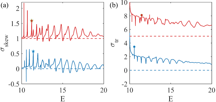
Figures 2(a) and 2(b) show, respectively, the skew scattering and transport cross sections as a function of incident electron energy, for a skyrmion (negative value of ) of circular shape (upper panel) and stadium shape (lower panel) of the same area in dimensionless units. The stadium shape is chosen because of its mirror symmetry for the incident plane waves so as to avoid an unnecessary complication: mixing of skew scattering and back-scattering (or reflection). For both skyrmion shapes, there are sharp resonant peaks in the skew cross section in the lower energy range close to the gap - an indication of the emergence of anomalous Hall effect associated with Dirac electron scattering from the skyrmion. As the incident energy is increased, the peak height is reduced but its width becomes larger, as a larger energy value corresponds to less distortion in the energy-momentum dispersion with the mass gap. Note that there is little difference in the skew scattering cross section curves for the two skyrmion shapes, indicating that the nature of the classical dynamics hardly affects the scattering. For the curves of the transport cross section, as shown in Fig. 2(b), its value decreases with increasing energy. For low energy values, the valleys in the transport cross section correspond exactly to the skew scattering peaks. Sharp peaks also exist in the backscattering cross section curve. Similar to the skew cross section, the nature of the classical dynamics has no appreciable effect. The results in Fig. 2 indicate that skyrmion skew scattering is robust against geometric deformations that are so severe as to change the classical behavior completely: from integrable dynamics to chaos.
Near-field behavior. To understand the origin of the deformation (chaos) independent far-field scattering (transport) behavior, we study the near-field scattering behavior by examining the probability density and the current density distribution associated with some specific energy state. In particular, the probability density is given by , where is the wavefunction, and the probability current operator is . The current density can be obtained as
| (12) |
The probability density distribution of the spin- component is given by
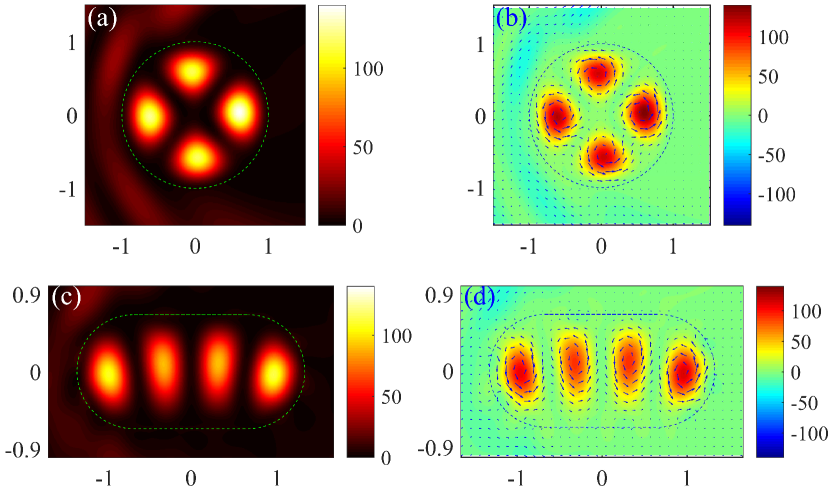
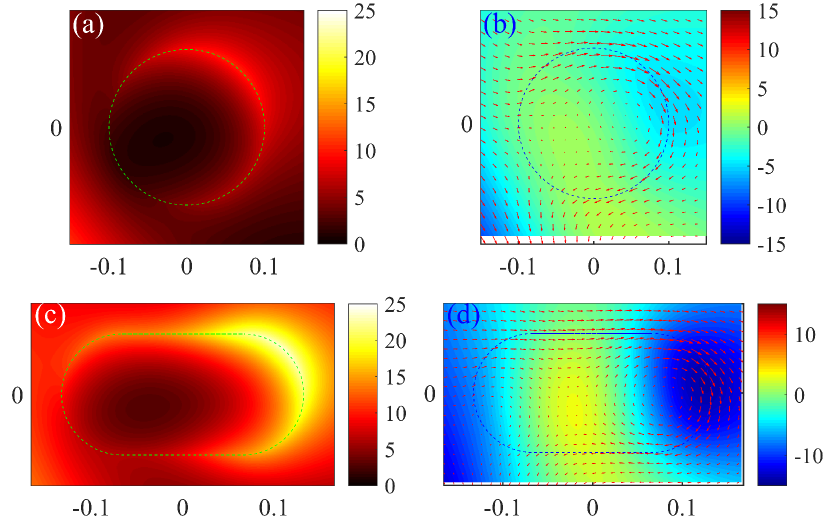
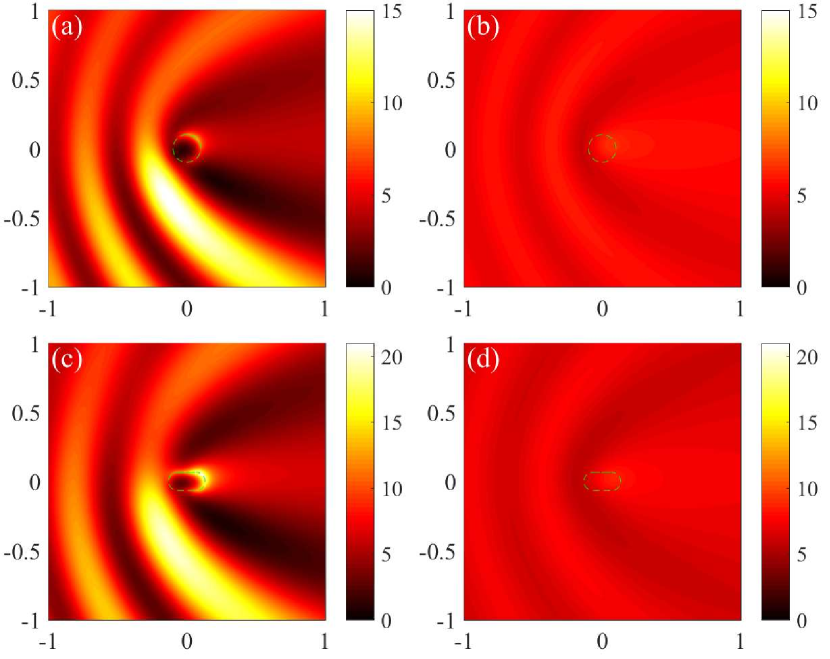
We choose a representative energy value corresponding to a skew scattering cross section peak: for the circular skyrmion and for the stadium-shaped skyrmion - marked as the red and blue stars in Fig. 2(a), respectively. The probability and the current density distributions are shown in Fig. 3. From both skyrmion structures, there are scattering resonant states, as shown in Figs. 3(a) and 3(c). The resonant patterns correspond to weak backscattering but stronger skew scattering cross sections, indicating that these are effectively quasi-confined states. Further insights into the contribution of the resonant states to skew scattering can be gained by examining the current density distribution (marked as arrows) and the spin- component density distribution (color coded) in the 2D skyrmion structure, as shown in Figs. 3(b) and 3(d). We see that the confined resonant states form vortices with counter-clockwise currents. There is also an out-of-plane spin component along the positive direction. The vortices have an apparent directionality, so they can affect the skew scattering direction and magnitude. The vortices are formed by interference of waves reflected from the boundary and are robust against boundary deformation. As a result, the nature of the classical dynamics, integrable or chaotic, has no significant effect on scattering.

In addition to the confined vortex states inside of the skyrmion structure, another form of confined states arises along the skyrmion boundary, as shown in Figs. 4(a) and 4(c), for scattering from a circular and a stadium-shaped skyrmion, respectively. There is strong confinement of the scattering wavefunction near the boundary with clockwise current and spin- component along the negative axis direction, as shown in Figs. 4(b) and 4(d). The edge states correspond to sharp resonant peaks in the backscattering cross section marked as the filled circles in Fig. 2(b). For the circular skyrmion, the edge states have no corresponding sharp peaks in skew scattering. For the stadium-shaped skyrmion, the edges states correspond to sharp valleys in the skew scattering cross section.
IV.2 Long wavelength regime - resonant modes near the boundary
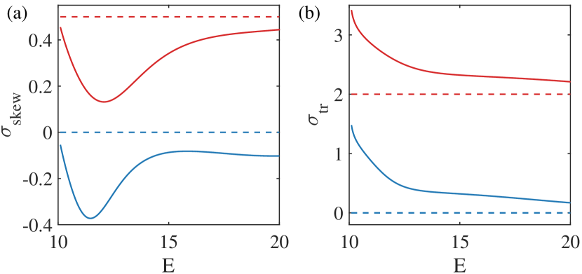
Far-field behavior. We consider the regime where the skyrmion size is smaller than the electronic wavelength: . This can be realized by setting the area of the skyrmion structure to be for both circular () and stadium-shaped skyrmions. In this long wavelength regime, for a deformed skyrmion structure, the MMP method is still effective for calculating the far-field cross sections and the near-field state distribution. Representative results on the skew scattering and transport cross sections versus the incident energy are shown in Fig. 5. Different from the scattering behaviors in the short wavelength regime, the oscillations of the skew scattering cross section with energy are weak. For example, in the energy range , only one smooth peak appears. There is hardly any difference in the scattering characteristics between the two skyrmion structures, which is understandable as any structural differences are not resolved in the long wavelength regime. Because of lack of appreciable oscillations, there is directional skew scattering over a large energy range - a desired feature in Hall device applications.
Near-field behavior. We examine the state associated with the energy value that leads to the lowest skew scattering cross section: for the circular and for the stadium-shaped skyrmion, and the respective probability density distributions are shown in Figs. 6(a) and 6(c). The states are concentrated in the vicinity of the boundary, which are different from the vortex states observed in the short-wavelength regime. The edge states thus represent a different type of resonant states with directional current, as shown in Figs. 6(b) and 6(d). It can be seen that the current direction is downward at the edge, contributing to skew scattering. The spin- component is along the negative direction.
IV.3 Further demonstration of strong skew scattering from a skyrmion structure
To further demonstrate the shape-independent skew scattering behavior of Dirac electrons from a magnetic structure, we study the effects of changing the mass of the skyrmion texture. To be concrete, we set and choose a set of positive and negative values. In this setting, there is a skyrmion for but the magnetic structure is non-skyrmion for .
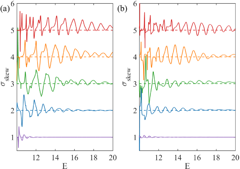
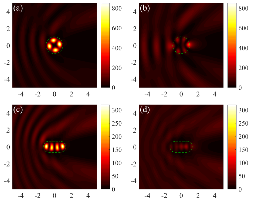
We first examine the short-wavelength regime to probe into the origin of the emerged confined vortex states. Figures 7(a) and 7(b) show the skew scattering cross sections for the circular and stadium-shaped magnetic structure, respectively, for and . It can be seen that, among the five cases, the resonant oscillations of the cross section with energy last longer for . On the contrary, for (non-skyrmion), the oscillations diminish rapidly as the energy is increased. These behaviors hold regardless of whether the underlying classical dynamics are integrable or chaotic. Overall, a large difference between the masses inside and outside of the magnetic structure can lead to stronger and long-lasting resonant modes and, consequently, to more pronounced skew scattering. Figures 8(a) and 8(b) show the probability density distribution for and , respectively, for the circular magnetic structure. The corresponding results for the stadium-shaped structure are shown in Figs. 8(c) and 8(d). For both structures, there are resonant modes for (when the magnetic structure is of the skyrmion type) but not for the case of .
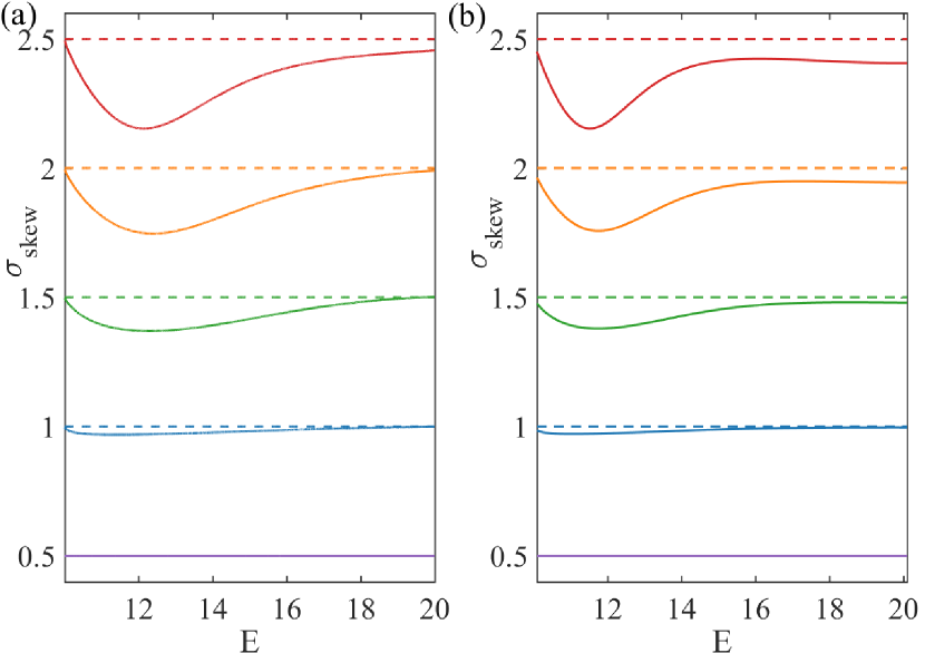
In the long wavelength regime, regardless of the shape of the magnetic structure (circular or stadium-shaped), the skew scattering cross section decreases as the relative mass difference is reduced, as shown in Fig. 9 for . Figure 10 shows representative resonant states for the circular and stadium-shaped structure for . Again, when the magnetic structure is of the skyrmion type, skew scattering is strong, making the scattering electrons directional. However, when the structure is not of the skyrmion type, skew scattering is weak.
V Partial-wave decomposition based analysis
Numerically, we have observed strong skew scattering of Dirac electrons from a skyrmion structure, which is robust against geometric deformation. We now provide an analytic understanding of skew scattering based on the method of partial wave decomposition. Consider a circular skyrmion. Key to pronounced skew scattering is the resonant modes emerged from the scattering process. In the short wavelength regime, a large number of angular momentum components are involved in the scattering, leading to a large number of resonant modes as the result of various combinations of the angular momentum components, which are manifested as peaks in the curve of the cross section with the energy. In the long wavelength regime, typically only a single resonant mode is dominant, implying the involvement of only the lowest several angular momentum components. The asymmetric contribution from different angular momentum channels leads to the observed pronounced skew scattering. Because the circular and stadium-shaped skyrmion structures generate similar scattering behavior, the analytic results from the circular skyrmion case also provides an understanding of the emergence of strong skew scattering in the stadium-shaped skyrmion.
For a circular skyrmion, the rotational symmetry stipulates conservation of the total angular momentum : , and the partial wave component with total angular momentum in the polar coordinates can be written as
| (13) |
The Hamiltonian in the polar coordinates is
| (14) |
Substituting the partial wave form in Eq. (13) into the Hamiltonian Eq. (14) leads to an eigenvalue problem and consequently to the explicit expression for the partial waves.
The transmitted wave inside of the skyrmion structure () can be expanded in terms of the partial waves as
| (15) |
and the reflected wave outside of skyrmion () can be written as
| (16) |
where is a normalization factor. We denote () as the magnetic moment and () as the wavevector outside (inside) of the skyrmion structure. For the incident electron in the free region outside of the skyrmion structure, the wavefunction is
| (17) |
Using the Jacobi-Anger identity:
| (18) |
we can expand the plane wave in the form
| (19) |
Matching the waves at the skyrmion boundary (r = R):
| (20) |
we get, after some algebraic manipulation,
| (21) |
and
| (22) |
where
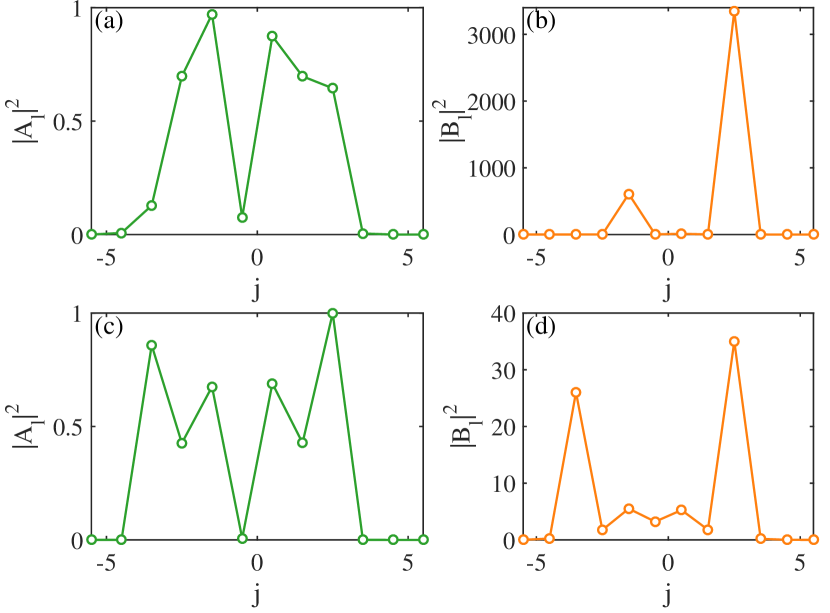
Using the explicit formulas for and as given in Eq. (21) and (22), respectively, we obtain the decomposition coefficients versus the total angular momentum for . Figures 11(a) and 11(b) show, for the case of scattering from a skyrmion structure ( and ), the expansion coefficients versus the total angular momentum . Figures 11(c) and 11(d) show the corresponding results for a non-skyrmion case ( and ). It can be seen that, several angular momentum components contribute to the reflected wave component , and the asymmetric distribution of the angular momentum components about zero leads to skew scattering. For the transmitted wave components, the distribution of the angular components is asymmetric as well, leading to the emergence of resonant vortices. For the coefficients, their values for the non-skyrmion case is much smaller than those for the skyrmion case, indicating that the skyrmion structure can confine the electrons much more effectively than the non-skyrmion structure.
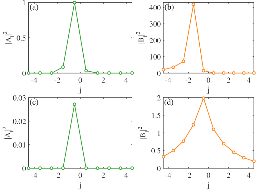
Setting lands the scattering system in the long wavelength regime. Figures 12(a,b) and 12(c,d) show the coefficients associated with different angular-momentum components for the skyrmion ( and ) and non-skyrmion ( and ) cases, respectively. In both cases, only a single angular momentum component contributes to the coefficient , i.e., , giving rise to the directionality in the scattering and a slow change in the resonant cross section with the energy. The value of for the non-skyrmion case is much smaller than that of the skyrmion case. For the transmitted coefficient , the angular momentum component dominates the skyrmion case and a number of components including have contributions in the non-skyrmion case, and the values of are much larger in the skyrmion than the non-skyrmion case, again implying stronger confinement by resonance and better directionality of scattering in the skyrmion structure as compared with those in the non-skyrmion structure.
VI Discussion
We have investigated relativistic quantum scattering of Dirac electrons from a closed magnetic structure embedded in the top surface of a 3D TI. Outside of the structure, there is a uniform FMI layer, leading to a finite but positive mass for the Dirac electron. The mass of the structure itself can be engineered to be negative or positive, where a skyrmion and a non-skyrmion structure arises in the former and latter case, respectively. In the short wavelength regime, the nature of the classical dynamics in the closed structure should be relevant to the quantum scattering dynamics, according to conventional wisdom from the study of quantum chaos Stöckmann (2006); Haake (2010). For a perfectly circular structure, the classical dynamics are integrable. For a deformed structure such as one with the stadium shape, there is fully developed chaos in the classical dynamics. Our main findings are two. Firstly, in the short wavelength regime, classical chaos hardly has any effect on the scattering dynamics. In fact, similar behaviors in the scattering characteristics at a quantitative level, such as the skew scattering and backscattering cross sections, have arise for the circular and stadium-shaped structures. The diminishing effects of classical chaos on relativistic quantum scattering from a magnetic structure are consistent with previous results on weakened manifestations of chaos in relativistic quantum systems in general Xu and Lai (2019); Han et al. (2019); Yang et al. (2011); Ying et al. (2012); Xu et al. (2015a). Secondly, strong skew scattering can arise when the magnetic structure is a skyrmion, regardless of the nature of the classical dynamics. In the short wavelength regime, the pronounced skew scattering is associated with resonant modes manifested as confined vortices inside of the skyrmion structure, which are originated from the sign change in the mass when the Dirac electrons travel from outside to inside of the skyrmion structure. A partial wave analysis for scattering from a circular skyrmion has revealed that a large number of angular momentum channels contribute to the resonant modes. We have also studied the long wavelength regime, where the geometric details of the magnetic structure are unresolved so naturally the scattering process is expected to be independent of the nature of the classical dynamics. In this regime, resonant states can still emerge as confined edge states inside of the magnetic structure, to which only a single angular momentum channel contributes, leading to highly directional skew scattering.
In the short wavelength regime, the resonant states manifested as confined vortices inside of the skyrmion structure can be exploited for electrically charging the skyrmion structure Nomura and Nagaosa (2010); Hurst et al. (2015), enabling the surface electrons on the TI to drive skyrmion motion with a low current and high thermal efficiency. In the long wavelength regime, the strong and robust directionality for skew scattering may be exploited for device application based on the anomalous Hall effect.
About experimental realization of a skyrmion structure, we note that there is recent evidence of magnetic skyrmion at the interface of the ferromagnet/TI (Cr2Te3/Bi2Te3) heterostructure Chen et al. (2019). In addition, inhomogeneous Zeeman coupling can be tuned for a ferromagnetic strip with strong out-of-plane magnetic anisotropy Hurst et al. (2015). For experimental control of electron scattering over a skyrmion structure, a quantum-dot type of configuration with skyrmion structure in a finite scattering region as well as with leads and contacts is necessary. The scattering configuration employed in our work is mainly for theoretical convenience with the goal to gain insights into the physics of electron scattering over the skyrmion structure with classical integrable or chaotic dynamics. For this purpose, the geometrical structure of the skyrmion is chosen to be either circular for which the scattering cross sections can be calculated analytically, or deformed for which the numerical method of multiple multipoles can be used to calculate the scattering wave function and consequently the resonant states, the cross sections, the current and spin distribution. Our results provide useful hints about the scattering of spin-1/2 fermion over a skyrmion structure. If the device size is significantly larger than the electron wavelength, we expect the main results to hold.
A number of open issues are worth studying, such as using spin transfer torque of the electrons to drive the skyrmion motion, exploitation of skyrmion related switches or oscillators, and scattering from multiple skyrmions that are themselves dynamic with possible phase-locking or anti-phase locking behavior.
Acknowledgements.
This work was supported by the Pentagon Vannevar Bush Faculty Fellowship program sponsored by the Basic Research Office of the Assistant Secretary of Defense for Research and Engineering and funded by the Office of Naval Research through Grant No. N00014-16-1-2828.Appendix: Multiple multipole (MMP) method for scattering of Dirac electrons on the top of a TI from a magnetic structure
We denote the area outside and inside of the skyrmion structure as regions and , respectively. The wavefunction in region can be written as
| (25) | |||
| (28) |
where
and are the expansion coefficients. The scattered wavefunction in region is
| (31) | |||
| (34) |
where
and are the expansion coefficients. The incident plane wave propagating along the direction defined by an angle with the axis in region is given by
| (37) | ||||
| (40) |
Matching the boundary conditions
| (41) | |||
| (42) |
we get
| (43) | |||||
and
| (45) |
which can be cast in a compact form as
| (46) |
| (47) |
where
| (48) | ||||
| (49) | ||||
| (50) | ||||
| (51) |
and
| (52) | ||||
| (53) |
In principle, the set consists of an infinite number of equations with an infinite number of undetermined expansion coefficients and . To solve the system numerically, finite truncation is necessary. We set the total number of boundary points to be with and poles in regions and , respectively, and for all the multipoles. The process leads to the following finite-dimensional matrix equation:
| (54) |
where ,
| (55) |
and
| (58) |
with
| (59) |
| (60) |
As the expansions are generally nonorthogonal, more equations are required than the number of unknowns to enable reduction of an overdetermined matrix system with , which can be solved by the pseudoinverse algorithm: .
References
- Nagaosa and Tokura (2013) N. Nagaosa and Y. Tokura, “Topological properties and dynamics of magnetic skyrmions,” Nat. Nanotech. 8, 899 (2013).
- Fert et al. (2013) A. Fert, V. Cros, and J. Sampaio, “Skyrmions on the track,” Nat. Nanotech. 8, 152 (2013).
- Everschor-Sitte et al. (2018) K. Everschor-Sitte, J. Masell, R. M. Reeve, and M. Kläui, “Perspective: Magnetic skyrmions - overview of recent progress in an active research field,” J. Appl. Phys. 124, 240901 (2018).
- Ochoa and Tserkovnyak (2018) H. Ochoa and Y. Tserkovnyak, “Colloquium: Quantum skyrmionics,” arXiv preprint arXiv:1807.02203 (2018).
- Mühlbauer et al. (2009) S. Mühlbauer, B. Binz, F. Jonietz, C. Pfleiderer, A. Rosch, A. Neubauer, R. Georgii, and P. Böni, “Skyrmion lattice in a chiral magnet,” Science 323, 915 (2009).
- Yu et al. (2010) X. Yu, Y. Onose, N. Kanazawa, J. Park, J. Han, Y. Matsui, N. Nagaosa, and Y. Tokura, “Real-space observation of a two-dimensional skyrmion crystal,” Nature 465, 901 (2010).
- Jonietz et al. (2010) F. Jonietz, S. Mühlbauer, C. Pfleiderer, A. Neubauer, W. Münzer, A. Bauer, T. Adams, R. Georgii, P. Böni, R. A. Duine, et al., “Spin transfer torques in MnSi at ultralow current densities,” Science 330, 1648 (2010).
- Zang et al. (2011) J. Zang, M. Mostovoy, J. H. Han, and N. Nagaosa, “Dynamics of skyrmion crystals in metallic thin films,” Phys. Rev. Lett. 107, 136804 (2011).
- Yu et al. (2012) X. Yu, N. Kanazawa, W. Zhang, T. Nagai, T. Hara, K. Kimoto, Y. Matsui, Y. Onose, and Y. Tokura, “Skyrmion flow near room temperature in an ultralow current density,” Nature communications 3, 988 (2012).
- Tsesses et al. (2018) S. Tsesses, E. Ostrovsky, K. Cohen, B. Gjonaj, N. Lindner, and G. Bartal, “Optical skyrmion lattice in evanescent electromagnetic fields,” Science 361, 993 (2018).
- Yin et al. (2015) G. Yin, Y. Liu, Y. Barlas, J. Zang, and R. K. Lake, “Topological spin Hall effect resulting from magnetic skyrmions,” Phys. Rev. B 92, 024411 (2015).
- Denisov et al. (2016) K. Denisov, I. Rozhansky, N. Averkiev, and E. Lähderanta, “Electron scattering on a magnetic skyrmion in the nonadiabatic approximation,” Phys. Rev. Lett. 117, 027202 (2016).
- Denisov et al. (2017) K. Denisov, I. Rozhansky, N. Averkiev, and E. Lähderanta, “A nontrivial crossover in topological Hall effect regimes,” Sci. Rep. 7, 17204 (2017).
- Ndiaye et al. (2017a) P. B. Ndiaye, C. A. Akosa, and A. Manchon, “Topological Hall and spin Hall effects in disordered skyrmionic textures,” Phys. Rev. B 95, 064426 (2017a).
- Denisov et al. (2018) K. Denisov, I. Rozhansky, M. N. Potkina, I. S. Lobanov, E. Lähderanta, and V. M. Uzdin, “Topological Hall effect for electron scattering on nanoscale skyrmions in external magnetic field,” Phys. Rev. B 98, 214407 (2018).
- Hasan and Kane (2010) M. Z. Hasan and C. L. Kane, “Colloquium: Topological insulators,” Rev. Mod. Phys. 82, 3045 (2010).
- Qi and Zhang (2011) X.-L. Qi and S.-C. Zhang, “Topological insulators and superconductors,” Rev. Mod. Phys. 83, 1057 (2011).
- Tserkovnyak and Loss (2012) Y. Tserkovnyak and D. Loss, “Thin-film magnetization dynamics on the surface of a topological insulator,” Phys. Rev. Lett. 108, 187201 (2012).
- Wei et al. (2013) P. Wei, F. Katmis, B. A. Assaf, H. Steinberg, P. Jarillo-Herrero, D. Heiman, and J. S. Moodera, “Exchange-coupling-induced symmetry breaking in topological insulators,” Phys. Rev. Lett. 110, 186807 (2013).
- Katmis et al. (2016) F. Katmis, V. Lauter, F. S. Nogueira, B. A. Assaf, M. E. Jamer, P. Wei, B. Satpati, J. W. Freeland, I. Eremin, D. Heiman, et al., “A high-temperature ferromagnetic topological insulating phase by proximity coupling,” Nature 533, 513 (2016).
- Yokoyama et al. (2010a) T. Yokoyama, Y. Tanaka, and N. Nagaosa, “Anomalous magnetoresistance of a two-dimensional ferromagnet/ferromagnet junction on the surface of a topological insulator,” Phys. Rev. B 81, 121401 (2010a).
- Wu et al. (2010) Z. Wu, F. Peeters, and K. Chang, “Electron tunneling through double magnetic barriers on the surface of a topological insulator,” Phys. Rev. B 82, 115211 (2010).
- Wang et al. (2016) G.-L. Wang, H.-Y. Xu, and Y.-C. Lai, “Nonlinear dynamics induced anomalous Hall effect in topological insulators,” Sci. Rep. 6, 19803 (2016).
- Wang et al. (2018a) G.-L. Wang, H.-Y. Xu, and Y.-C. Lai, “Emergence, evolution, and control of multistability in a hybrid topological quantum/classical system,” Chaos 28, 033601 (2018a).
- Garate and Franz (2010) I. Garate and M. Franz, “Inverse spin-galvanic effect in the interface between a topological insulator and a ferromagnet,” Phys. Rev. Lett. 104, 146802 (2010).
- Yokoyama et al. (2010b) T. Yokoyama, J. Zang, and N. Nagaosa, “Theoretical study of the dynamics of magnetization on the topological surface,” Phys. Rev. B 81, 241410 (2010b).
- Yokoyama (2011) T. Yokoyama, “Current-induced magnetization reversal on the surface of a topological insulator,” Phys. Rev. B 84, 113407 (2011).
- Semenov et al. (2014) Y. G. Semenov, X. Duan, and K. W. Kim, “Voltage-driven magnetic bifurcations in nanomagnet–topological insulator heterostructures,” Phys. Rev. B 89, 201405 (2014).
- Duan et al. (2015) X. Duan, X.-L. Li, Y. G. Semenov, and K. W. Kim, “Nonlinear magnetic dynamics in a nanomagnet–topological insulator heterostructure,” Phys. Rev. B 92, 115429 (2015).
- Ndiaye et al. (2017b) P. B. Ndiaye, C. A. Akosa, M. H. Fischer, A. Vaezi, E.-A. Kim, and A. Manchon, “Dirac spin-orbit torques and charge pumping at the surface of topological insulators,” Phys. Rev. B 96, 014408 (2017b).
- Wang et al. (2018b) C.-Z. Wang, H.-Y. Xu, N. D. Rizzo, R. A. Kiehl, and Y.-C. Lai, “Phase locking of a pair of ferromagnetic nano-oscillators on a topological insulator,” Phys. Rev. Appl. 10, 064003 (2018b).
- Nomura and Nagaosa (2010) K. Nomura and N. Nagaosa, “Electric charging of magnetic textures on the surface of a topological insulator,” Phys. Rev. B 82, 161401 (2010).
- Hurst et al. (2015) H. M. Hurst, D. K. Efimkin, J. Zang, and V. Galitski, “Charged skyrmions on the surface of a topological insulator,” Phys. Rev. B 91, 060401 (2015).
- Araki and Nomura (2017) Y. Araki and K. Nomura, “Skyrmion-induced anomalous Hall conductivity on topological insulator surfaces,” Phys. Rev. B 96, 165303 (2017).
- Zhang et al. (2016) X. Zhang, J. Xia, Y. Zhou, D. Wang, X. Liu, W. Zhao, and M. Ezawa, “Control and manipulation of a magnetic skyrmionium in nanostructures,” Phys. Rev. B 94, 094420 (2016).
- Pylypovskyi et al. (2018) O. V. Pylypovskyi, D. Makarov, V. P. Kravchuk, Y. Gaididei, A. Saxena, and D. D. Sheka, “Chiral skyrmion and skyrmionium states engineered by the gradient of curvature,” Phys. Rev. Applied 10, 064057 (2018).
- Göbel et al. (2019) B. Göbel, A. Schäffer, J. Berakdar, I. Mertig, and S. Parkin, “Electrical writing, deleting, reading, and moving of magnetic skyrmioniums in a racetrack device,” Sci. Rep. 9, 12119 (2019).
- Nogueira et al. (2018) F. S. Nogueira, I. Eremin, F. Katmis, J. S. Moodera, J. van den Brink, and V. P. Kravchuk, “Fluctuation-induced Néel and Bloch skyrmions at topological insulator surfaces,” Phys. Rev. B 98, 060401 (2018).
- Garnier et al. (2019) M. Garnier, A. Mesaros, and P. Simon, “Topological superconductivity with deformable magnetic skyrmions,” Commun. Phys. 2, 126 (2019).
- Rachel et al. (2017) S. Rachel, E. Mascot, S. Cocklin, M. Vojta, and D. K. Morr, “Quantized charge transport in chiral Majorana edge modes,” Phys. Rev. B 96, 205131 (2017).
- Mascot et al. (2018) E. Mascot, S. Cocklin, S. Rachel, and D. K. Morr, “Quantum engineering of Majorana fermions,” arXiv preprint arXiv:1811.06664 (2018).
- Güngördü et al. (2018) U. Güngördü, S. Sandhoefner, and A. A. Kovalev, “Stabilization and control of Majorana bound states with elongated skyrmions,” Phys. Rev. B 97, 115136 (2018).
- Liu et al. (2018) Y. Liu, R. K. Lake, and J. Zang, “Shape dependent resonant modes of skyrmions in magnetic nanodisks,” J. Mag. Magnet. Mater. 455, 9 (2018).
- Berry and Mondragon (1987) M. V. Berry and R. J. Mondragon, “Neutrino billiards - time-reversal symmetry-breaking without magnetic-fields,” Proc. R. Soc. London Series A Math. Phys. Eng. Sci. 412, 53 (1987).
- Lai et al. (2018) Y.-C. Lai, H.-Y. Xu, L. Huang, and C. Grebogi, “Relativistic quantum chaos: An emergent interdisciplinary field,” Chaos 28, 052101 (2018).
- Huang et al. (2018) L. Huang, H.-Y. Xu, C. Grebogi, and Y.-C. Lai, “Relativistic quantum chaos,” Phys. Rep. 753, 1 (2018).
- Neto and Novoselov (2011) A. H. C. Neto and K. Novoselov, “Two-dimensional crystals: Beyond graphene,” Mater. Exp. 1, 10 (2011).
- Ajayan et al. (2016) P. Ajayan, P. Kim, and K. Banerjee, “Two-dimensional van der Waals materials,” Phys. Today 69, 38 (2016).
- Stöckmann (2006) H.-J. Stöckmann, Quantum Chaos: An Introduction (Cambridge University Press, New York, 2006).
- Haake (2010) F. Haake, Quantum Signatures of Chaos, 3rd ed., Springer series in synergetics (Springer-Verlag, Berlin, 2010).
- Xu and Lai (2019) H.-Y. Xu and Y.-C. Lai, “Pseudospin-1 wave scattering that defies chaos Q-spoiling and Klein tunneling,” Phys. Rev. B 99, 235403 (2019).
- Han et al. (2019) C.-D. Han, H.-Y. Xu, L. Huang, and Y.-C. Lai, “Manifestations of chaos in relativistic quantum systems - a study based on out-of-time-order correlator,” Phys. Open 1, 100001 (2019).
- Blümel and Smilansky (1988) R. Blümel and U. Smilansky, “Classical irregular scattering and its quantum-mechanical implications,” Phys. Rev. Lett. 60, 477 (1988).
- Jalabert. et al. (1990) R. A. Jalabert., H. U. Baranger, and A. D. Stone, “Conductance fluctuations in the ballistic regime - a probe of quantum chaos,” Phys. Rev. Lett. 65, 2442 (1990).
- Lai et al. (1992) Y.-C. Lai, R. Blümel, E. Ott, and C. Grebogi, “Quantum manifestations of chaotic scattering,” Phys. Rev. Lett. 68, 3491 (1992).
- Marcus et al. (1992) C. M. Marcus, A. J. Rimberg, R. M. Westervelt, P. F. Hopkins, and A. C. Gossard, “Conductance fluctuations and chaotic scattering in ballistic microstructures,” Phys. Rev. Lett. 69, 506 (1992).
- Ketzmerick (1996) R. Ketzmerick, “Fractal conductance fluctuations in generic chaotic cavities,” Phys. Rev. B 54, 10841 (1996).
- Yang et al. (2012) R. Yang, L. Huang, Y.-C. Lai, and L. M. Pecora, “Modulating quantum transport by transient chaos,” Appl. Phys. Lett. 100, 093105 (2012).
- Yang et al. (2011) R. Yang, L. Huang, Y.-C. Lai, and C. Grebogi, “Quantum chaotic scattering in graphene systems,” Europhys. Lett. 94, 40004 (2011).
- Ying et al. (2012) L. Ying, L. Huang, Y.-C. Lai, and C. Grebogi, “Conductance fluctuations in graphene systems: The relevance of classical dynamics,” Phys. Rev. B 85, 245448 (2012).
- Xu et al. (2015a) H.-Y. Xu, L. Huang, Y.-C. Lai, and C. Grebogi, “Superpersistent currents and whispering gallery modes in relativistic quantum chaotic systems,” Sci. Rep. 5, 8963 (2015a).
- Xu et al. (2015b) H.-Y. Xu, L. Huang, and Y.-C. Lai, “Robust relativistic qubit,” Preprint (2015b).
- Larkin and Ovchinnikov (1969) A. Larkin and Y. N. Ovchinnikov, “Quasiclassical method in the theory of superconductivity,” Sov. Phys. JETP 28, 1200 (1969).
- Schütte and Garst (2014) C. Schütte and M. Garst, “Magnon-skyrmion scattering in chiral magnets,” Phys. Rev. B 90, 094423 (2014).
- Leviatan and Boag (1987) Y. Leviatan and A. Boag, “Analysis of electromagnetic scattering from dielectric cylinders using a multifilament current model,” IEEE Trans. Anten. Propa. 35, 1119 (1987).
- Imhof (1996) M. G. Imhof, “Multiple multipole expansions for elastic scattering,” J. Acous. Soc. Am. 100, 2969 (1996).
- Kaklamani and Anastassiu (2002) D. I. Kaklamani and H. T. Anastassiu, “Aspects of the method of auxiliary sources (mas) in computational electromagnetics,” IEEE Anten. Propag. Maga. 44, 48 (2002).
- Moreno et al. (2002) E. Moreno, D. Erni, C. Hafner, and R. Vahldieck, “Multiple multipole method with automatic multipole setting applied to the simulation of surface plasmons in metallic nanostructures,” J. Opt. Soc. Am. A 19, 101 (2002).
- Tayeb and Enoch (2004) G. Tayeb and S. Enoch, “Combined fictitious-sources–scattering-matrix method,” J. Opt. Soc. Am. A 21, 1417 (2004).
- Chen et al. (2019) J. Chen, L. Wang, M. Zhang, L. Zhou, R. Zhang, L. Jin, X. Wang, H. Qin, Y. Qiu, J. Mei, et al., “Evidence for magnetic skyrmions at the interface of ferromagnet/topological-insulator heterostructures,” Nano Lett. 19, 6144 (2019).