[1]Apostolos Apostolakis
Superlattice nonlinearities for Gigahertz-Terahertz generation in harmonic multipliers
Abstract
Semiconductor superlattices are strongly nonlinear media offering several technological challenges associated with the generation of high-frequency Gigahertz radiation and very effective frequency multiplication up to several Terahertz. However, charge accumulation, traps and interface defects lead to pronounced asymmetries in the nonlinear current flow, from which high harmonic generation stems. This problem requires a full non-perturbative solution of asymmetric current flow under irradiation, which we deliver in this paper within the Boltzmann-Bloch approach. We investigate the nonlinear output on both frequency and time domains and demonstrate a significant enhancement of even harmonics by tuning the interface quality. Moreover, we find that increasing arbitrarily the input power is not a solution for high nonlinear output, in contrast with materials described by conventional susceptibilities. There is a complex combination of asymmetry and power values leading to maximum high harmonic generation.
1 Introduction
The inherent nonlinearities of electronic systems can be exploited for the development of novel compact sources in the terahertz (THz) region [1, 2, 3, 4, 5]. The very same nonlinearities and their underlying microscopic origin serve as sensitive means for controlling high harmonic generation (HHG) processes. A notable very recent example is the generation of THz harmonics in a single-layer graphene due to hot Dirac fermionic dynamics under low-electric field conditions [6].
In a parallel effort, advances in strong-field and attosecond physics have paved the way to HHG in bulk crystals operating in a highly nonperturbative regime [7, 8, 9, 10, 11]. The first experimental observation of non-perturbative HHG in a bulk crystal was explained on the
basis of a simple two-step model in which the nonlinearity stemmed from the anharmonicity of electronic motion in the band combined with multiple Bragg reflections at the zone boundaries [12]. The high frequency (HF) nonlinearities which contribute to harmonic upconversion in bulk semiconductors have been associated to dynamical Bloch oscillations combined with coherent interband polarization processes [7, 13]. The aforementioned models allow the use of tight-binding dispersions [14] to describe the electronic band and therefore the radiation from a nonlinear intraband current. One of the systems that demonstrate a similar highly nonparabolic energy dispersion are man-made semiconductor superlattices (SSLs) [15, 16]. In fact, the possibility of spontaneous frequency multiplication due to the effect of nonparabolicity in a SSL miniband structure was first predicted in the early works of Esaki-Tsu [17] and Romanov [18]. Superlattices are created by alternating layers of two semiconductor materials with similar lattice constants resulting in the formation of a spatial periodic potential. Furthermore, SSLs host rich dynamics in the presence of a driving field, which include the formation of Stark ladders [19], the manifestation of Bragg reflections and Bloch oscillations [20]. From the viewpoint of applications, SSLs have attracted great interest because they allow the development of devices which operate at microwave [21] and far-infrared frequencies [21, 5] suitable for high precision spectroscopic studies and detection of submillimeter waves. In addition, a considerable number of studies have tackled the task of engineering parametric amplifiers [22, 23] and frequency multipliers [24, 25, 26] based on superlattice periodic structures. Note that although the first semiconductor superlattice frequency multipliers (SSLM) were developed for the generation of microwave radiation [27], significant progress has been achieved combining high-frequency operation (up to 8.1 THz, 50th harmonic) [25, 5] and high conversion efficiency [28] comparable to the performance of Schottky diodes [28, 29].
There are various mechanisms that contribute to the HF nonlinearities of SSL devices. Once this distinction has been clearly made, it is simple to connect the underlying physical mechanisms to the frequency multiplication effects. It was found that spontaneous multiplication takes place in a dc biased tight-binding SSL, when the Bloch-oscillating electron wave packet is driven by the input oscillating field [30, 31]. Moreover, the increase of optical response [30] was due to the frequency modulation of Bloch oscillations [32, 33] which arise in the negative differential conductivity (NDC) region of the current-voltage characteristic, i.e. the current decreases with increasing bias.
On the other hand, if a SSL device is in a NDC state, the nonlinearities can be further enhanced by the onset of high-field domains [34, 35] and the related propagation phenomena [36] in a similar way as the electric-field domains in bulk semiconductors [37]. Thus, the ultrafast creation and annihilation of electric domains during the time-period of an oscillating field contributes to harmonic generation processes in SSLs [38]. This type of dynamics has been found to depend on plasma effects [39, 40] induced by the space-charge instabilities and the dielectric relaxation time processes which dictate the exact conditions for the NDC state [40]. The expected THz response from Bloch oscillations in a miniband SSL, under the influence of a THz electric field, might also deviate due to strong excitonic effects [41, 42, 43].
Harvesting the nonlinearities discussed above can potentially lead to more efficient SSLMs or other devices suitable for achieving extremely flexible frequency tuning.
Our approach is inspired by very recent theoretical and experimental investigations [26, 44, 45, 46] of SSLM behavior, which revealed the development of even harmonics due to imperfections in the superlattice structure. In general, when a adequately strong oscillating field couples energy into the SSLM in the absence of constant bias, only odd harmonics are emitted. However, Ref. [26] showed that symmetry breaking was induced by asymmetric current flow and scattering processes under forward and reverse bias. This approach combined nonequilibrium Green’s function calculations with an Ansatz solution of the Boltzmann equation in the relaxation rate approximation. Furthermore, the asymmetric scattering rates were attributed to the different elastic (interface roughness) scattering rates which have risen from the non-identical qualities of the SSL interfaces. In general, elastic scattering processes can have a significant effect on the electron transport in semiconductor superlattices.The conventional method to study the role of elastic scattering on miniband transport and generation of high-frequency radiation [47, 48] are the one dimensional (1D) SSL Balance equations [47] which can be extended to address two-dimensional and three-dimensional [49, 50] SSL transport and optical properties. They cannot, however, include systematically the different scattering processes under forward and reverse bias. A handful of experiments have been devoted to examine the harmonics of current oscillations [35], transient THz response [51], dephasing mechanisms of Bloch oscillations [52] and the electron mobility [53] under the influence of isotropic-elastic-scattering time.
In this paper, we elucidate how the effects of asymmetric scattering processes could be used to control the implications of the SL potential on the response of miniband electrons to an oscillating electric field . We solve the Boltzmann transport equation (BTE) by the method of characteristics [54, 55], which allows to address explicitily the asymmetric intraminiband relaxation processes in semiconductor superlattices. Earlier in Refs. [56, 57] the relaxation rate was assumed to depend on the electron velocity allowing to estimate analytically the high-frequency conductivity of an asymmetric superlattice but with resorting to perturbative analysis of the Boltzmann equation. Before proceeding further it is worthwhile first to highlight the main points of this work:
(i) We eliminate the numerical instabilities which originate from the Ansatz solution of Ref. [26, 58].
(ii) Our solution delivers a time-domain analysis of the mechanism responsible for the built up of high harmonic generation.
(iii) We theoretically demonstrate that the multiplication effects can be effectively controlled by special designs of superlattice interfaces (asymmetric elastic scattering).
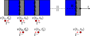
The anisotropic effects [26] reflect that typically the interfaces of a host material (A) grown on an different host material (B) are found to be rougher than those of B on A (see Fig. 1), indicating grading or intermixing of the constituent materials between SSL layers [59, 60].
This paper is organised as follows. Section 2 provides an overview of a semiclassical theory describing the charge transport in SSLs in the presence of asymmetric scattering. In Sec. 3, we discuss the nonlinear optical response of miniband electrons in an asymmetric SL structure and we present results of exact numerical simulations describing the spontaneous HHG. Complementary insight is provided next with time-domain calculations. In Appendix A, we revisit in more detail the expressions related to the solution of the BTE which is implemented in this work. On the other hand, Appendix B entails analytical solutions for HHG based on an Ansatz that can lead to numerical instabilities to highlight our more efficient solution.
2 Semiclassical formulation
Throughout this work we use the standard energy dispersion, , which describes the kinetic energy carried by an electron in the lowest SL miniband [15, 16]. Here is the center of the miniband, is the miniband quarter-width, is the projection of crystal momentum on the –axis (axis parallel to the general grown direction) and is the superlattice period. Note that in this transport model, the effects of inter-miniband tunneling are neglected. To simulate the temporal distribution function of the single electron, we employ a semiclassical approach based on the Boltzmann transport equation [16]
| (1) |
where is the force corresponding to a time dependent electric field in the –direction of the SSL and k is the total momentum which can decomposed into and the quasimomentum in the – plane . The right-hand side term of Eq. (1) represents the collision integral. Instead of using a single relaxation rate approximation model equivalent to [61] with being the equilibrium fermi distribution, we will resort to two scattering rates to adequately describe the asymmetric relaxation processes. The asymmetric elastic scattering would result to enhanced scattering processes into certain directions. Thus, the kinetic equation can be rewritten in the following form
| (2) |
where are integral operators corresponding to the different relaxation rates ( and ). By using the inverse of the operator, , on the left of Eq. (2), we obtained the time-dependent current density
| (3) |
where is integrated over the Brillouin zone, the integration limits of the in-plane components are and controls the level of current flow asymmetry. Equation (3) summarizes that an electron which passes through the point at time , follows different collisionless trajectories which takes it through the points at times . This compact solution requires the assumption of the following condition for the relaxation energy
| (4) |
Here represents the time-dependent miniband velocity which reveals the propagation direction of the electron along the sample and therefore indicates the interaction with the high-quality or low-quality interface [see Fig. 1]. For a further discussion of Eqs. (2)-(4) see Appendix A. The time dependence of the velocity is obtained from the set of the equations
| (5a) | |||
| (5b) | |||
where the parameter critically affects the strength of the nonlinear optical response and consequently the harmonic-conversion properties of the SSLM.
The Fourier transform of the time-dependent current [Eq. (3)] can be used to obtain spectral peaks at multiples of the driving frequency. In particular, the intensity of the emitted radiation from the SSL structure is determined by the Poynting vector, which is proportional to the harmonic current term [26]
| (6) |
where the integration signifies time-averaging over time interval of infinite time in the general case. Nevertheless, considering that the current response is induced merely by a monochromatic field , it is sufficient to average only over the time-period . Both even and odd harmonics are present in a biased SSL due to symmetry breaking. However, in this paper we focus on symmetry breaking due structural effects leading to asymmetric current flow. Thus in all numerical results for harmonic generation, there is no static electric field, i.e. 0 and the Bragg reflections from minizone boundaries are not assigned to Bloch oscillations (BO) with the conventional oscillation frequency . In contrast, the Bragg scattering is manifested as frequency modulation of electron oscillations during a cycle () of the oscillating field. Oscillations of this type are known as Bloch oscillations in a harmonic field (BOHF) [33]. Combining the Bloch acceleration theorem [Εq. (5a)] and the energy dispersion , one can find the dependence of miniband energy on time
| (7) |
where and , are bessel functions of the first kind. From Eq. (7) we see that the electron energy oscillates within the miniband with frequency at every even mupltiple of : with On the contrary, the miniband velocity varies at every odd multiple of : with stemming directly from the equation which is derived, just as Eq. (7), from a real-valued expression of Jacobi-Anger expansion [62]. Due to the collisions the electron experiences damped BOHF and thus the latter equation can be used as an input for the solution of the BTE [see Eq. (3)]. Hereafter, it becomes clear that the Boltzmann-Bloch transport theory requires a self-consistent solution of the Boltzmann transport equation and the semiclassical equations of motion obeyed by Bloch momentum . In the quasistatic limit the electron performs high quality BOHF when . Here with designating the energy required from the ac-field in order to bring temporarily the SSL to an active state equivalent to the NDC region of the VI characteristic result to the formation of high electric field domains which act as additional linearities. We must underline that in this work the high-frequency field considered to be acting on the superlattice leads to a single-electron state and the electric field within the SSL remains uniform. As a result, the gain at some harmonics of the oscillating field is related only to the nonlinearity of the voltage-current characteristic and the BOHF oscillations. The condition [Eq. (4)] dictates the different relaxation times or , reflecting on the coefficient =1 or in Eq. (3). This asymmetry coefficient plays an important role in this work, since it indicates the differences between the interfaces leading to deviation from the perfectly anti-symmetric voltage of the Esaki and Tsu model [15]. See Fig. 7 per se in Appendix B. An increase of can be interpreted as a structural variation of the initial SSL structure. In the present work we assume that which implies that the flow from left to right will be favored over the flow from right to left. Furthermore, the asymmetry coefficient depends on the elastic and inelastic scattering rates, which are either determined from measured values [35, 63] or nonequilibrium Green’s functions calculations [26, 45]. It is important to notice that similar kinetic formulas to Eq. (3) have been used to treat the different types of scattering processes in superlattices [64, 65]. However, none of these works have systematically included a tensor analyzing the different relaxation processes which correspond to an asymmetric SSL structure. In this paper, the values of the SSL parameters in Eqs. (3)-(5) are taken from recent experiments and predictive simulations [26, 44]: nm, meV, =21 meV, =2.14 and the corresponding critical field is kV/mm. For the integration of the equation of motions (5a), (5b)
we implement the classical fourth-order Runge-Kutta method known for its stability [66].
Before moving forward with results, we should make a brief recap of a previous research. A NEGF approach, in which the different interfaces were described by using an interface roughness self-energy, gave good agreement with static current voltage, but could not be implemented for a GHz input. Thus, this predictive input was used in a hybrid NEGF-Boltzmann equation approach by employing a analyical Ansatz solution for the asymmetric current flow [26, 44, 45, 46]. However, the Ansatz leads in some cases to numerical instabilities and errors as shown in Fig. 2. This is one of the main motivations of this paper, which delivers a clean numerical solution that does not need the Ansatz. For correctness the analytical Ansatz solution is described in Appendix B.
3 Results
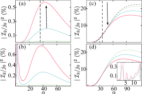
In this section we will investigate the effects of asymmetric scattering on HHG by implementing the approach developed in the previous section and compare its predictions to those of the analytical Ansatz solution. The basic idea is to vary the asymmetry coefficient which in both approaches is defined as the ratio of the different relaxation rates () and then examine the effects on even and odd order harmonics. Figure 2 depicts the second harmonic (left-handed panels) and third harmonic output (right-handed panels) as a function of the parameter for different values of the asymmetry coefficient . The dependencies were calculated using Eqs. (15)–(19) and Eqs. (3)–(6) in Fig. 2(a) and Fig. 2(b), respectively. Both approaches yield similar results for the second harmonic in a wide range of . In particular, we highlight that asymmetric relaxation times are an unconventional mechanism for frequency doubling in SSLs. As increases, the frequency doubling effects become more pronounced and, eventually, give rise to stronger optical response almost up to 0.6 . We note that the Ansatz solution may, however, contribute to nonphysical numerical instabilities by revealing intense second harmonic generation even at small amplitudes of the oscillating field. Therefore, the numerical solution offers a reliable way to treat the scattering induced asymmetries in the current flow. Now we turn our attention to the third harmonic output in the presence of asymmetric current flow which is quite different from the behavior of the second harmonic output. Moreover, increasing suppresses it, implying an redistribution of spectral components in favor of even harmonics as shown in Fig. 2(d). One can see that the maximum output of the third harmonic might be potentially reduced from 20 to 15 . In this case the different solutions appear to be more consistent with each other. However, as shown in the inset of Fig. 2(d) the Ansatz solution can lead to numerical instabilities comparable with the maximum output of the second harmonic. Once we established that the novel approach developed in this work affords the significant variation of the asymmetry coefficient, we can have an in-depth look into the HHG processes.
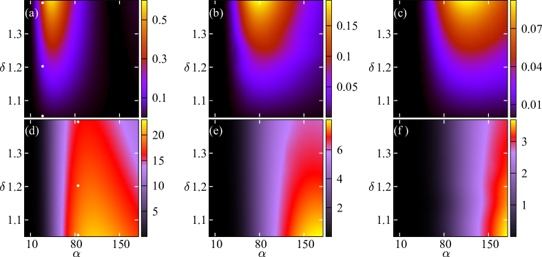
Further insight on how asymmetric effects can result in a significant gain at some even harmonic frequencies and suppression at some other odd-order harmonics, is given by the color maps in Fig. 3. It shows the calculated values as a function of and . The black area indicates values (, ) for which exhibits small or negligible harmonic response. The colored areas unfold distinct islands of significant harmonic response. For example, Fig. 3(a) reveals significant enhancement of for and . On the other hand, in the same region Fig. 3(d) demonstrates a weak third harmonic response of the irradiated superlattice. The corresponding island of enhanced is shifted to significantly larger values. The magnitude of increases approximately from to and thus obtaining a maximum for a SSL structure with perfectly symmetric interfaces. The width of the islands changes significantly for the higher-order even harmonics as shown in Figs. 3(b) and 3(c). However, although the width of the colored islands is increased, the strength of the harmonic content is reduced, by an order of magnitude for [Fig. 3(c)] in comparison with [Fig. 3(a)]. The colored areas of the higher-odd harmonics are notably suppressed in the regions where higher-even harmonics are being developed. Therefore, in order to achieve easily detectable odd harmonics the SSL should operate deep inside the NDC region. At this point it is important to highlight that the higher the harmonic order, the larger the input power must be. However, note that arbitrarily increasing the input power is not a solution for high nonlinear output, in contrast with materials described by conventional susceptibilities. There is a complex combination of asymmetry and power values leading to maximum HHG generation. For example, Fig. 4 demonstrates the output of higher even-order harmonics (beyond the 2nd harmonic) which drastically drops when the input power is significantly larger. The SSL device after excitation by a strong GHz input signal can generate measurable 8th harmonic up to 0.02 . The magnitude of the emitted power in units \textmugreekW is related to harmonic term as = where the coefficient obtained from the time-averaged Poynting vector by neglecting the waveguide effects. Here is the permeability and is the speed of light by considering both of them in free-space. For typical mesa area (10 10) , effective path length through the crystal 121.4 nm and refractive index = (GaAs), one can obtain \textmugreekW. Now it is straightforward to calculate the emitted power corresponding to Figs. (2-4). As a consequence, for a value close to but below the the emitted power can reach the values \textmugreekW and \textmugreekW at room temperature for the second and fourth harmonic respectively. These magnitudes indicate that significant gain can appear at second and fourth-order harmonics in the absence of electric domains which might affect the HHG processes when .
Next, we complement the steady-state analysis with calculations of the time-dependent nonlinear response of the miniband electrons. Our time-dependent solution [see Eq. 3] can provide further insight in the frequency-conversion of the input signal related to the asymmetric scattering processes.
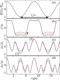
Figure 5 depicts the oscillating field, the nonlinear current oscillations, the second harmonic component and the third harmonic component which occur in the presence of asymmetric scattering rates. The oscillating field [see Fig. 5(a)] causes a time-dependent electron drift with a time dependent current which contains different harmonic components due to the enhanced nonlinear response as shown in Fig. 5(b).

In a perfectly symmetric structure, the irradiation of the superlattice with input radiation leads only to odd-order multiplication and therefore the second harmonic signal [dashed curve in Fig. 5(c)] averaged over time is . On the contrary, for a higher asymmetry parameter (arrowed), the time realization of demonstrates oscillations whose amplitude is highly asymmetric. In this case, the the first peak (1) becomes sufficiently smaller than peak (2) resulting in different than zero as is evident from Fig. 5(c). The third harmonic component in the current is due to the BOHF which stem from the anharmonic motion of the electron within the miniband. Every half-period (), contributes a phase of an opposite sign with respect to the temporal evolution of the electric field [see Fig. 5(a), (d)]. With increasing asymmetry coefficient , the amplitude of the arrowed peak is reduced, which leads to suppression of the third harmonic component .
For a electric field with sufficiently larger amplitude but with the same oscillating frequency, the current response becomes evidently more anharmonic [see Fig. 6(b)]. This has important implications for both second and third-order harmonics and serious consequences in the case of increasing the asymmetry parameter .

On the one hand, the increase of the asymmetry between the two relaxation rates results in more pronounced differences between the oscillations amplitudes (1), (2) of the second harmonic and their adjacent peaks [Fig. 6(c)]. Consequently, the second harmonic is suppressed for a larger but still enhanced for a different . On the other hand, the parameter being larger than would induce higher quality BOHF and therefore larger third harmonic components [Fig. 6(d)]. We note though that a larger asymmetry will reduce the emission of due to the strong suppression of the closely neighboring peaks to the main one.
Before summarizing the main results of this paper, it is noteworthy to highlight further immediate applications of our approach. Evidently the electron energy oscillates within the miniband with frequency at every even multiple of the frequency of the oscillating electric field [see Eq. (3)]. The behaviour of effective electron mass, which explicitly depends on energy [67], varies significantly in the presence of highly asymmetric scattering and thus the generated harmonics could be linked to the concept of negative effective mass similar to [68]. Significant production of even harmonics has been previously predicted for an electrically excited SSL due to parametric amplification [69] or other parametric processes [70] which stem from the existence of an internal electric field in the structure. In this respect, it is interesting to study how the parametric processes can affect the harmonic generation [71] or the Bloch gain [70] profile in the presence of asymmetric current flow. Moreover, our approach has a great potential for analyzing the effects of asymmetric scattering processes on the intensity of harmonics by means of externally applied voltages and/or intense ultrafast optical pulses [51, 43]. Finally, the predictions in the present work highlight the prospects for the systematic study of asymmetric effects in different superlattice systems including coupled superlattices in a synchronous state [72] and, even more generally, in other multilayer structures such as high temperature superconductors [73].
4 Conclusions
In summary, the Boltzmann-Bloch approach is used to deliver general, non-perturbative solutions of High Harmonic Generation in semiconductor superlattices. This method allows us to investigate details of the generation processes in both spectral and time domains. The non-approximative nature of our approach eliminates numerical errors which could cast doubt upon the origin of harmonic generation. Thus, our study conclusively demonstrates striking features of High Harmonic Generation when asymmetric relaxation processes are taken into account in superlattice structures. While these effects are relatively small on the odd harmonic generation, significant features appear at even harmonics leading to measurable effects in the GHz-THz range. Our algorithms have immediate potential to analyse the combination of asymmetric flow with parametric processes, externally applied voltages and ultrafast optical pulses. Future work should focus on investigating thoroughly the conditions for formation of destructive electric domains in semiconductor superlattices in the case of harmonic generation due to asymmetric scattering processes.
The authors acknowledge support by the Czech Science Foundation (GAČR) through grant No. 19-03765 and the EU H2020-Europe’s resilience to crises and disasters program (H2020–grant agreement no. 832876, AQUA3S). Access to computing and storage facilities owned by parties and projects contributing to the National Grid Infrastructure MetaCentrum provided under the programme “Projects of Large Research, Development, and Innovations Infrastructures” (CESNET LM2015042) is greatly appreciated.
Appendix A Formulations of superlattice transport equations
In this section, we revisit expressions describing a solution to SSL transport problems and having as a starting point the Boltzmann equation. The general formalism has been applied to describe transport in semiconducting devices [74], parametric amplification [22] and Bloch gain [75] in spatially homogeneous SSLs. This method allows us to deliver a general numerical solution for the influence of asymmetric relaxation effects on miniband transport model and frequency multiplication processes in superlattices in the presence of an oscillating electric field, eliminating the need for the approximative Ansatz used in Refs. [26, 44, 45, 46]. The electron distribution function satisfies the spatially homogeneous Boltzmann equation
| (8) |
The second term of the right-hand side of Eq. (8) represents the rate of change of due to collisions, which is characterized conventionally by the transition probability per unit time that an electron will be scattered out of a state into a volume element and the rate per unit tame that an electron with wave vector will scatter to a state whose vector lies between and . We can rearrange Eq. (8) as
| (9) |
Thus, if a single and isotropic (same for all states k) relaxation rate is assumed then and Eq. (9) has an solution in the form . The latter equation has been derived using the method of characteristics by Ignatov et. al. to investigate the nonlinear electromagnetic properties of SSLs [55]. We note that in the case of anisotropic scattering the Eq. (9) can be rewritten in a form of the following integral equation
| (10) |
We would like to localize the asymmetry of the electron scattering function due to interface roughness to well-defined regions of the SSL. Therefore, we assume that if and and both lie in within a region of the miniband for which , otherwise . Accordingly, the operator is generalized into
| (11a) | |||
| (11b) | |||
and
| (12) |
indicating the existence of two scattering rates due to differences in interface roughness depending on the sequence of the layers. Here for simplicity we designate the region in -space as corresponding to the high-quality interface of the SSL. Equations (9) and (11a), (11b) can be combined into the single integro-differential Eq. (2). The latter equation may be solved to obtain the current with asymmetric relaxation processes. The resulting expression is described by
| (13) |
Note that the static current is obtained by taking in Eq. (13). In that case the peak current , corresponding to the critical field reads
| (14) |
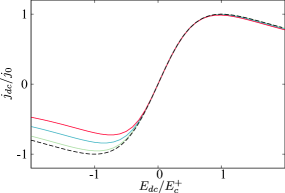
Figure 7 demonstrates versus calculated numerically for different values of . In contrast to the case of (dashed curve), all other curves in Fig. 7 exhibit maximum and minimum currents at different . Interestingly, as increases, the Esaki-Tsu peak (i.e. =) weakens slightly whereas the peaks at the opposite bias are notably suppressed. We see that the asymmetric current flow is dramatically enhanced by considering scattering processes increasingly asymmetric under forward and reverse bias. We should comment here that our approach is qualitatively different from the balance equations approach developed in [76] and discussed further in Refs. [47, 48]. This 1D model assumed that the distribution function can be decomposed into its symmetric and anti-symmetric parts. The basic idea is that in the presence of inelastic scattering processes () is allowed to relax to equilibrium distribution function . On the other hand, couples the motion only in the –direction to that in the –direction via elastic scattering ) transferring the energy obtained by the electron transport along the field direction. As a result the current density-electric field dependence can be obtained by the kinetic formula where denotes averaging over time and . This model predicts effectively the suppression of peak current density with the increase of . It cannot, however, treat in its present form the asymmetric relaxation rates and their effects on harmonic generation in the presence of a time-dependent electric field, in contrast to our more general approach.
Appendix B Ansatz analytical solution
In this section we will give a recap of the analytical ansatz solution previously used to describe asymmetric current flow and the effects of asymmetric scattering on HHG [26, 44, 45, 46]. Thus, one can consider a SSL with period under an electric field . The time-dependence of the current response is then described by the Fourier basis
| (15) | |||
| (16) | |||
| (17) | |||
| (18) |
where the dc current () is given by Eq. (16) and the Fourier components describe the lth harmonic generation. The terms in Eqs. (16)–(18) denote the Bessel functions of the first kind and order . It can also be seen from Eq. (16) that the voltage current (VI) characteristics in the presence of irradiation [] is given by a sum of shifted Esaki-Tsu characteristics where is the peak current corresponding to the critical electrical field . This might lead to a photon-assisted tunneling phenomenon that has been experimentally observed [16, 77]. Moreover, note that the term designates an effective potential difference instead of the plain potential drop per period due to the dc bias. The function is connected to through Kramers-Kronig relations. It is thus sufficient for our studies to look at the resulting average similar to Eq. (6) , in order to investigate spontaneous frequency multiplication effects. The ansatz is implemented by replacing in Eqs. (15)-(18) by
| (19) |
where the potential energy is equal to integer number of photon quanta () and the asymmetry coefficient is .
References
- [1] Dhillon S, Vitiello M, Linfield E, et al. The 2017 terahertz science and technology roadmap. J Phys D 2017;50:043001.
- [2] Tonouchi M. Cutting-edge terahertz technology. Nat Photonics 2007;1:97.
- [3] Blanchard F, Sharma G, Razzari L, et al. Generation of intense terahertz radiation via optical methods. IEEE J Sel Top Quantum Electron 2010;17:5–16.
- [4] Chen Z, Morandotti R. Nonlinear photonics and novel optical phenomena. Springer, 2012.
- [5] Vaks V. High-precise spectrometry of the terahertz frequency range: the methods, approaches and applications. J Infrared Millim Terahertz Waves 2012;33:43–53.
- [6] Hafez HA, Kovalev S, Deinert JC, et al. Extremely efficient terahertz high-harmonic generation in graphene by hot dirac fermions. Nature 2018;561:507.
- [7] Schubert O, Hohenleutner M, Langer F, et al. Sub-cycle control of terahertz high-harmonic generation by dynamical bloch oscillations. Nat Photonics 2014;8:119.
- [8] Langer F, Hohenleutner M, Schmid C, et al. Lightwave-driven quasiparticle collisions on a subcycle timescale. Nature 2016;533:225.
- [9] Drescher M, Hentschel M, Kienberger R, et al. X-ray pulses approaching the attosecond frontier. Science 2001;291:1923–7.
- [10] Smirnova O, Mairesse Y, Patchkovskii S, et al. High harmonic interferometry of multi-electron dynamics in molecules. Nature 2009;460:972.
- [11] Krausz F, Ivanov M. Attosecond physics. Rev Mod Phys 2009;81:163.
- [12] Ghimire S, DiChiara AD, Sistrunk E, et al. Observation of high-order harmonic generation in a bulk crystal. Nat Phys 2011;7:138.
- [13] Hohenleutner M, Langer F, Schubert O, et al. Real-time observation of interfering crystal electrons in high-harmonic generation. Nature 2015;523:572.
- [14] Golde D, Meier T, Koch SW. High harmonics generated in semiconductor nanostructures by the coupled dynamics of optical inter-and intraband excitations. Phys Rev B 2008;77:075330.
- [15] Esaki L, Tsu R. Superlattice and negative differential conductivity in semiconductors. IBM J Res Dev 1970;14:61–5.
- [16] Wacker A. Semiconductor superlattices: a model system for nonlinear transport. Phys Rep 2002;357:1–111.
- [17] Tsu R, Esaki L. Nonlinear optical response of conduction electrons in a superlattice. Appl Phys Lett 1971;19:246–8.
- [18] Romanov YA. Nonlinear effects in periodic semiconductor structures (frequency multiplication due to nonparabolicity of dispersion law in semiconductor structure subbands, noting electromagnetic signal transformation). Opt Spec 1972;33:917–20.
- [19] Mendez EE, Agullo-Rueda F, Hong JM. Stark localization in gaas-gaalas superlattices under an electric field. Phys Rev Lett 1988;60:2426.
- [20] Waschke C, Roskos HG, Schwedler R, et al. Coherent submillimeter-wave emission from bloch oscillations in a semiconductor superlattice. Phys Rev Lett 1993;70:3319.
- [21] Khosropanah P, Baryshev A, Zhang W, et al. Phase locking of a 2.7 THz quantum cascade laser to a microwave reference. Opt Lett 2009;34:2958–0.
- [22] Renk KF, Stahl BI, Rogl A, et al. Subterahertz superlattice parametric oscillator. Phys Rev Lett 2005;95:126801.
- [23] Renk KF, Rogl A, Stahl BI. Semiconductor-superlattice parametric oscillator for generation of sub-terahertz and terahertz waves. J Lumin 2007;125:252–8.
- [24] Klappenberger F, Renk KF, Renk P, et al. Semiconductor–superlattice frequency multiplier for generation of submillimeter waves. Appl Phys Lett 2004;84:3924–6.
- [25] Paveliev DG, Koshurinov YI, Ivanov AS, et al. Experimental study of frequency multipliers based on a GaAs/AlAs semiconductor superlattices in the terahertz frequency range. Semiconductors 2012;46:121–5.
- [26] Pereira MF, Zubelli JP, Winge D, et al. Theory and measurements of harmonic generation in semiconductor superlattices with applications in the 100 GHz to 1 THz range. Phys Rev B 2017;96:045306.
- [27] Grenzer J, Ignatov AA, Schomburg E, et al. Microwave oscillator based on bloch oscillations of electrons in a semiconductor superlattice. Ann Phys 1995;507:184–90.
- [28] Endres CP, Lewen F, Giesen TF, et al. Application of superlattice multipliers for high-resolution terahertz spectroscopy. Rev Sci Instrum 2007;78:043106.
- [29] Siles JV, Grajal J. Physics-based design and optimization of schottky diode frequency multipliers for terahertz applications. IEEE Trans. Microw Theory Tech 2010;58:1933–42.
- [30] Winnerl S, Schomburg E, Brandl S, et al. Frequency doubling and tripling of terahertz radiation in a GaAs/AlAs superlattice due to frequency modulation of bloch oscillations. Appl Phys Lett 2000;77:1259–61.
- [31] Schomburg E, Grenzer J, Hofbeck K, et al. Superlattice frequency multiplier for generation of submillimeter waves. IEEE J Sel Top Quantum Electron 1996;2:724–8.
- [32] Ignatov AA, Schomburg E, Grenzer J, et al. THz-field induced nonlinear transport and dc voltage generation in a semiconductor superlattice due to bloch oscillations. Z Phys B 1995;98:187–95.
- [33] Romanov YA, Romanova YY. Bloch oscillations in superlattices: The problem of a terahertz oscillator. Semiconductors 2005;39:147–55.
- [34] Le Person H, Minot C, Boni L, et al. Gunn oscillations up to 20 GHz optically induced in GaAs/AlAs superlattice. Appl Phys Lett 1992;60:2397–9.
- [35] Schomburg E, Blomeier T, Hofbeck K, et al. Current oscillation in superlattices with different miniband widths. Phys Rev B 1998;58:4035.
- [36] Makarov VV, Hramov AE, Koronovskii AA, et al. Sub-terahertz amplification in a semiconductor superlattice with moving charge domains. Appl Phys Lett 2015;106:043503.
- [37] Gunn J. Instabilities of current in iii–v semiconductors. IBM J Res Dev 1964;8:141–59.
- [38] Scheuerer R, Haeussler M, Renk KF, et al. Frequency multiplication of microwave radiation by propagating space-charge domains in a semiconductor superlattice. Appl Phys Lett 2003;82:2826–8.
- [39] Pamplin BR. Negative differential conductivity effects in semiconductors. Contemporary Physics 1970;11:1–19.
- [40] Klappenberger F, Alekseev KN, Renk KF, et al. Ultrafast creation and annihilation of space-charge domains in a semiconductor superlattice observed by use of terahertz fields. Eur Phys J B 2004;39:483–9.
- [41] Meier T, Von Plessen G, Thomas P, et al. Coherent electric-field effects in semiconductors. Phys Review Lett 1994;73:902.
- [42] Dignam M. Excitonic bloch oscillations in a terahertz field. Physl Rev B 1999;59:5770.
- [43] Wang D, Zhang A, Yang L, et al. Tunable terahertz amplification in optically excited biased semiconductor superlattices: Influence of excited excitonic states. Phys Rev B 2008;77:115307.
- [44] Pereira MF, Anfertev VA, Zubelli JP, et al. Terahertz generation by gigahertz multiplication in superlattices. J Nanophotonics 2017;11:046022.
- [45] Apostolakis A, Pereira MF. Controlling the harmonic conversion efficiency in semiconductor superlattices by interface roughness design. AIP Advances 2019;9:015022.
- [46] Apostolakis A, Pereira MF. Potential and limits of superlattice multipliers coupled to different input power sources. J Nanophotonics 2019;13:1 – 11.
- [47] Ignatov AA, Dodin EP, Shashkin VI. Transient response theory of semiconductor superlattices: connection with bloch oscillations. Mod Phys Lett B 1991;5:1087–94.
- [48] Alekseev KN, Cannon EH, McKinney JC, et al. Spontaneous dc current generation in a resistively shunted semiconductor superlattice driven by a terahertz field. Phys Rev Lett 1998;80:2669.
- [49] Gerhardts RR. Effect of elastic scattering on miniband transport in semiconductor superlattices. Phys Rev B 1993;48:9178.
- [50] Romanov YA, Romanova JY, Mourokh LG, et al. Self-induced and induced transparencies of two-dimensional and three-dimensional superlattices. Phys Rev B 2002;66:045319.
- [51] Ferreira R, Unuma T, Hirakawa K, et al. A Boltzmann approach to transient Bloch emission from semiconductor superlattices. Appl Phys Expr 2009;2:062101.
- [52] Unuma T, Sekine N, Hirakawa K. Dephasing of bloch oscillating electrons in GaAs-based superlattices due to interface roughness scattering. Appl phys Lett 2006;89:161913.
- [53] Sakaki H, Noda T, Hirakawa K, et al. Interface roughness scattering in GaAs/AlAs quantum wells. Appl phys Lett 1987;51:1934–6.
- [54] Chambers RG. The kinetic formulation of conduction problems. Proc Phys Soc Sec A 1952;65:458.
- [55] Ignatov A, Romanov YA. Nonlinear electromagnetic properties of semiconductors with a superlattice. Phys Stat Sol B 1976;73:327–33.
- [56] Shmelev GM, Maglevanny II, Bulygin AS. Current-voltage characteristic of asymmetric superlattice. Physica C: Superconductivity 1997;292:73–8.
- [57] Shmelev GM, Soina NA, Maglevannyi II. High-frequency conductivity of an asymmetric superlattice. Phys Solid State 1998;40:1574–76.
- [58] The theory developed in [26] leads to results similar to those obtained in the present work qualitively and numerically. However, the enhanced asymmetries cause numerical instabilities for a small parameter .
- [59] Feenstra RM, Collins DA, Ting DY, et al. Interface roughness and asymmetry in InAs/GaSb superlattices studied by scanning tunneling microscopy. Phys Rev Let 1994;72:2749.
- [60] Tokura Y, Saku T, Tarucha S, et al. Anisotropic roughness scattering at a heterostructure interface. Phys Rev B 1992;46:15558.
- [61] Ashcroft NW, Mermin ND. Solid State Physics. Philadelphia, Saunders College, 1976.
- [62] Abramowitz M, Stegun IA, Romer RH. Handbook of mathematical functions with formulas, graphs, and mathematical tables. American Association of Physics Teachers, 1988.
- [63] Patanè A, Sherwood D, Eaves L, et al. Tailoring the electronic properties of GaAs/AlAs superlattices by inas layer insertions. Appl Phys Lett 2002;81:661–3.
- [64] Fromhold TM, Patane A, Bujkiewicz S, et al. Chaotic electron diffusion through stochastic webs enhances current flow in superlattices. Nature 2004;428:726.
- [65] Greenaway MT, Balanov AG, Schöll E, et al. Controlling and enhancing terahertz collective electron dynamics in superlattices by chaos-assisted miniband transport. Phys Rev B 2009;80:205318.
- [66] Press WH, Teukolsky SA, Vetterling WT, et al. Numerical recipes in Fortran 77: the art of scientific computing. Cambridge, Cambridge university press, 1992.
- [67] Ignatov AA, Renk KF, Dodin EP. Esaki-Tsu superlattice oscillator: Josephson-like dynamics of carriers. Phys Rev Lett 1993;70:1996.
- [68] Shorokhov AV, Pyataev MA, Khvastunov NN, et al. Physical principles of the amplification of electromagnetic radiation due to negative electron masses in a semiconductor superlattice. JETP Lett 2015;100:766–70.
- [69] Hyart T, Alexeeva NV, Leppänen A, et al. Terahertz parametric gain in semiconductor superlattices in the absence of electric domains. Appl Physics Lett 2006;89:132105.
- [70] Romanov YA, Romanova YY. Self-oscillations in semiconductor superlattices. J of Exp and Theor Phys 2000;91:1033–45.
- [71] Hyart T, Shorokhov AV, Alekseev KN. Theory of parametric amplification in superlattices. Phys Rev Lett 2007;98:220404.
- [72] Matharu S, Kusmartsev FV, Balanov AG. High-frequency generation in two coupled semiconductor superlattices. Eur Phys J Special Topics 2013;222:2559–70.
- [73] Yampol’skii VA, Savel’ev S, Usatenko OV, et al. Controlled terahertz frequency response and transparency of Josephson chains and superconducting multilayers. Phys Rev B 2007;75:014527.
- [74] Budd H. Path variable formulation of the hot carrier problem. Phys Rev 1967;158:798.
- [75] Hyart T, Mattas J, Alekseev KN. Model of the influence of an external magnetic field on the gain of terahertz radiation from semiconductor superlattices. Phys Rev Lett 2009;103:117401.
- [76] Ignatov AA. Self-induced transparency in semiconductors with superlattices. Phys Solid State 1975;17:2216–7.
- [77] Wacker A, Jauho AP, Zeuner S, et al. Sequential tunneling in doped superlattices: Fingerprints of impurity bands and photon-assisted tunneling. Phys Rev B Nov 1997;56:13268–78.