One-way reflection-free exciton-polariton spin filtering channel
Abstract
We consider theoretically exciton-polaritons in a strip of honeycomb lattice with zigzag edges and it is shown that the interplay among the spin-orbit coupling, Zeeman splitting, and an onsite detuning between sublattices can give rise to a band structure where all the edge states of the system split in energy. Within an energy interval, one of the spin polarized edge states resides with the gap-less bulk having opposite spin. Being surrounded by opposite spin and the absence of the backward propagating edge state ensures both reflection free and feedback suppressed one-way flow of polaritons with one particular spin in the system. The edge states in this system are more localized than those in the standard topological polariton systems and are fully spin polarized. This paves the way for feedback free spin-selective polariton channels for transferring information in polariton networks.
Introduction— It has been recognized long ago that one of the crucial ingredients for optical circuits is the isolation of input and output Keyes_1985 . Equivalently, circuits should operate in a one-way fashion, where feedback in the backward direction is suppressed. As Maxwell’s equations are time reversal invariant, the realization of such a requirement is not obvious in many optical systems, and reflections must be considered carefully. With the emergence of topological photonics Lu_2014 ; Ozawa_2019 , special techniques were introduced to artificially break time-reversal symmetry (e.g., helical waveguide arrays as in Floquet topological insulators Lindner_2011 ) or exotic material solutions employed at particular wavelengths (e.g., magnetically sensitive gyrotropic materials Wang_2009 ). One of the well-known features of topological photonic lattices is the appearance of chiral edge states. As these propagate in only a certain direction and do not undergo backscattering, it has been natural to expect that such states are relevant for the robust propagation of optical signals.
Instead of breaking time-reversal symmetry directly in a photonic system, an alternative is to couple it to a system in which time-reversal symmetry is broken. In particular, when photons are coupled to excitons in semiconductor micropillars they hybridize to form exciton-polaritons, which inherit a Zeeman splitting due to their excitonic component when placed in a magnetic field Rahimi-Iman_2011 . Since such micropillars can be arranged into lattices it has been possible to form topological polariton systems Klembt_2018 , accounting for the effect of spin-orbit coupling Karzig_2015 ; Bardyn_2015 ; Nalitov_2015 .
Exciton-polaritons also exhibit a significant nonlinearity, which in theory was predicted to itself induce topological behavior Bardyn_2016 , antichiral behavior Mandal_2019 , and topological solitons Kartashov_2016 . Separate from topological physics, nonlinearity was shown to provide low-energy polaritonic switches Grosso_2014 ; Dreismann_2016 ; Lewandowski_2017 and realize other information processing elements such as transistors Gao_2012 ; Ballarini_2013 ; Lewandowski_2017 ; Zasedatelev_2019 , routers Flayac_2013 ; Marsault_2015 ; Schmutzler_2015 , and amplifiers Wertz_2012 ; Niemietz_2016 . The possible use of topological polariton states at the edges of a strip to couple these elements suffers however from an obvious drawback: such states come in pairs, which propagate in opposite directions on the opposite edges of the strip Bardyn_2015 ; Nalitov_2015 . Consequently, there will be an unwanted counter-propagating signal at the opposite edge of the strip leading to potentially detrimental feedback (unless the strip is made very wide, which would lead to other problems in scalability).
Furthermore, it has long been expected that polaritonic devices would make use of the spin degree of freedom Shelykh_2004 , which can take one of two spin projections on the structure growth axis (denoted ). Individual spin switches Amo_2010 and gates Gao_2015 have encoded information in this spin. Unfortunately though, topological polariton states have a specific polarization that mixes the and components Bardyn_2015 ; Nalitov_2015 , which would not allow the preservation of individual or spin polarized wavepackets.
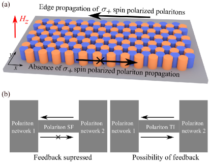
In this work, we aim to develop the recent advances in topological polariton physics to introduce a channel for connecting polaritons of a given spin. We aim for the channel to be reasonably thin and allow only one spin to propagate in a specific direction. To meet this aim, we consider a strip of honeycomb polariton lattice, which is composed of two interlocking sublattices, A and B (see Fig. 1(a)). The sites of the different sublattices are engineered with different onsite energy. Accounting for a magnetic field and spin-orbit coupling, we find that the states at different edges are split in energy and become almost completely spin polarized. Furthermore, an edge state of a given spin can be embedded in an energy range where the only existing states have opposite spin polarization. As the scattering of polaritons with disorder tends to be spin conserving, this maintains a unidirectional propagating edge state for a specific spin, which is not possible with a regular topological polariton system (see Fig. 1(b)). A further key difference with existing topological polariton realizations is that the strip can be made remarkably thin (three lattice constants thick) and still maintain its unidirectional spin polarized behavior.
Scheme— We start by considering a planar semiconductor microcavity containing exciton-polaritons subjected to a resonant excitation, expressed by the driven dissipative Schrdinger equation,
| (1) |
Here are the wave functions for spin polarized polaritons; is a potential describing a strip of honeycomb lattice having zigzag edges along the direction; is a uniform decay throughout the sample; and are the Zeeman and TE-TM splittings, respectively. are the circular polarization components of a resonant excitation with frequency . Each micropillar is modelled by placing a Gaussian of width at each site Kartashov_2017 and the lattice has a periodicity along the direction, such that,
| (2) |
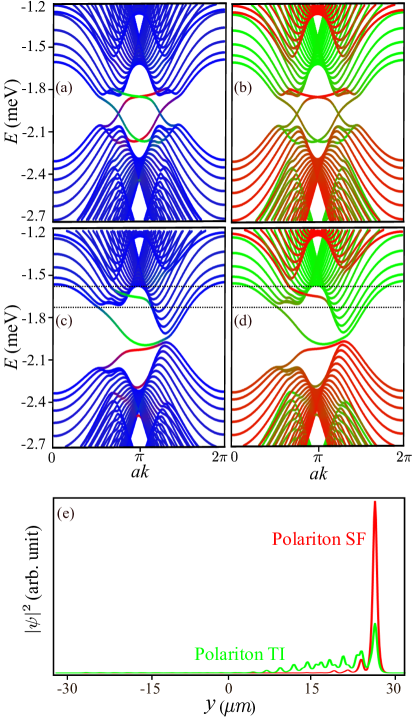
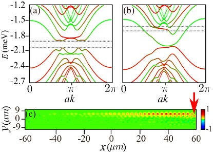
Here the summation runs over all sites, is the potential depth corresponding to the A sublattices, and is the potential depth corresponding to the B sublattices. In principle, the energy detuning, , between the A and B sublattices can be induced by locally adjusting the thickness of the cavity or by non-resonantly pumping one of the sublattices, where the excitonic reservoir will induce a blueshift locally Galbiati_2012 . Alternatively, micropillars corresponding to the A and B sublattices could be engineered with different diameters (see the supplementary material (SM)). In order to know the characteristics of the system we consider the linear band structure by setting and in Eq. (One-way reflection-free exciton-polariton spin filtering channel) and after applying the Bloch theorem the wave function can be written as, . Here are the Bloch wave functions, which are periodic along the direction and is the wave-vector in the direction. Upon substitution, Eq. (One-way reflection-free exciton-polariton spin filtering channel) leads to an eigenvalue problem, which can be solved to obtain the band structure. In Figs. 2 (a-b) and (c-d) we plot the dispersion without and with the onsite term, respectively. For , we obtain the band structure corresponding to the polariton topological insulator (TI) (see Fig. 2 (a)) where the time reversal symmetry is broken by the Zeeman splitting. Here, the bulk modes are gapped and in the band gap robust edge states appear. In this case, the edge states come in counter propagating pairs, meaning that within the band gap of each propagating edge state there is another one propagating in the opposite direction. The inclusion of breaks the inversion symmetry and the parameters can be chosen such that the band gap at one of the Dirac points gets closed resulting in a topologically trivial system. The dispersion of the bulk modes is similar to the ones in bilayer graphene with a perpendicular bias Foa_2016 . Although, in this case the edge states are completely separated in energy (see Fig. 2 (b)). Note that there is no counter propagating edge mode present in the energy window of interest. We have also plotted the localization of the edge states in Fig. 2(e), which shows that the edge states in the spin filter (SF) regime are more localized than the standard polariton TI.
To emphasize the interest of the obtained states, we plot the band structures and colour code them depending upon the contribution of the spins. In the case of a polariton TI (see Fig. 2 (b)) we find that within the bandgap the edge states have mixed spin. On the other hand in the SF regime (Fig. 2 (d)) the edge states have almost pure spin and more importantly the top most edge state is surrounded by only the bulk modes with opposite spin polarization. We can then expect spin polarized polaritons to propagate through the edge mode without backscattering, manifesting a robust SF.
Considering typical parameters, we have set: m; with the free electron mass; meV; meV; m; meVm2; and meV. This gives an energy interval of the SF edge state of around 0.12 meV, which is well above the linewidth of modern samples. Generally, the SF regime can be found for , where is the trivial bandgap induced by the broken inversion symetry (see SM Figs. S1- S3) and determines the group velocity of the edge state. It should be stressed that instead of the magnetic field (Zeeman splitting), the nonresonant excitation can itself break the symmetry between the two spins Bleu_2016 ; Sigurdsson_2019 . For the rest of the paper we will focus on the top most edge state and although here only spin polarized polaritons are filtered, the same can be done for the spin polarized polaritons (see SM).
Spin filtering— To validate our claim we excite the top most edge state resonantly with a continuous linearly polarized Gaussian shaped pump by setting . The spin polarization degree is defined as,
| (3) |
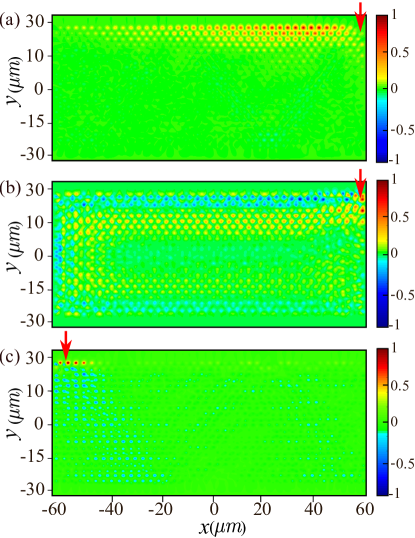
The spatial distribution of is plotted in Fig. 3(a) in the SF regime, which shows that although we have excited both spin states, only spin polarized polaritons populate the top edge and propagate over from the spot of excitation. Due to the finite lifetime the intensity decreases with the increase of propagation distance. spin polarized polaritons are instead scattered randomly into the bulk. To demonstrate that there is no state of spin polarized polaritons to propagate in the reverse direction, we consider injecting both spins from the opposite corner of the top edge (see Fig. 3(c)). We observe that the spin polarized polaritons can not propagate from left to right of the system; instead they are converted to polaritons and scatter into the bulk. This confirms that the system can act as a feedback free unidirectional spin filter. On the other hand, in a polariton TI the polaritons with mixed spins rotate through the edges of the sample in anticlockwise direction (See Fig. 3(b)). Although the exact contribution of the spins in can be changed slightly depending upon the state that is being excited, there is always a significant contribution from both the spins.
In all our calculations, we have taken a lifetime around 60 ps, close to that reported in Klembt_2018 ; Galbiati_2012 . The SF would also work with shorter lifetime, although the propagation distance would decrease (see SM, Fig. S3). Higher lifetimes such as those reported in Sun_2017 are thus the ideal.
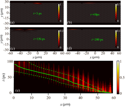
Pulse propagation around defect— Fig. 4 (a-d) consider the propagation of a polarized pulse (obtained by multiplying the coherent excitation with a Gaussian in time) in the case where a micropillar is removed from the top edge. We observe that near the defect the pulse spreads a little but does not backscatter and after some time the pulse passes the defect. This further proves the robustness of the edge state.
Propagation in the presence of disorder— In real systems, disorder is present throughout. Fig. 4 (e) shows the propagation of a polarized pulse in the presence of a continuous disorder potential, which is characterized by a root mean squared amplitude of eV and a correlation length of m (corresponding to typical experimental values Baboux_2016 ). Again, no backscattering of the polarized wavepacket is observed.
Strip width— In addition to supporting one-way propagation, a channel for connecting information processing elements should not be too wide, so as not to limit the footprint area of future systems. In Figs. 5 (a-b) the band structure for a narrow strip having three unit cells along the direction is plotted for a polariton TI and SF, respectively. Due to the lack of bulk states, the well spread edge states in the polariton TI (see Fig. 2(e)) vanish while comparatively more localized edge states in the polariton SF remain unaffected resulting in spin propagation as shown in Fig. 5 (c).
Discussion— Modern electronic devices and integrated circuits are limited by heating and time delay of communication between components. Optical devices seem promising candidates for fast interconnections and higher fidelity may reduce error correction overhead, resulting in less heating Miller_2017 . But optics needs to operate at lower threshold to be relevant, for which nonlinear optical systems are essential. Along with the nonlinearity, the spin degree freedom of exciton-polaritons make them extremely promising for nonlinear spintronics devices. The coupling between the exciton polariton condensates in lattices have been demonstrated but this coupling is always bidirectional and consequently, there will be unwanted feedback. Although the proposed spin filter is not itself a device it can be an essential component of complete future circuits or networks.
Conclusion— We have proposed theoretically a scheme to obtain an optical spin filter based on exciton-polaritons. The naturally present spin orbit interaction along with Zeeman splitting and an onsite detuning between sublattices in a polariton honeycomb lattice gives rise to a band structure where all the edge states of the system split in energy and there exists an energy window where one of the edge states with pure spin is surrounded by bulk states with opposite spin. Since there is no state with the same spin to backscatter to, polaritons having one of the spins in the system can propagate robustly through the edge state and thus spin filtering is achieved. The absence of the pairing backward propagating edge state reduces feedback in the system. Furthermore, the edge state in the polariton SF is more localized than those in a polariton TI, which allows to operate with very narrow channels. In contrast, regular polariton TI systems would require much wider strips/lattices to support robust propagation and would cause mixing between spin polarized states.
Acknowledgement— The work was supported by the Ministry of Education, Singapore (grant nos. MOE2018-T2-02-068 and MOE2018-T3-1-002).
References
- (1) R. W. Keyes, “What Makes a Good Computer Device?” Science 230, 138 (1985).
- (2) L. Lu, J. D. Joannopoulos, and M. Soljacic, “Topological photonics” Nature Photon. 8, 821 (2014).
- (3) T. Ozawa, H. M. Price, A. Amo, N. Goldman, M. Hafezi, L. Lu, M. C. Rechtsman, D. Schuster, J. Simon, O. Zilberberg, and I. Carusotto, “Topological photonics” Rev. Mod. Phys. 91, 015006 (2019).
- (4) N. H. Lindner, G. Refael, and V. Galitski, “Floquet Topological Insulator in Semiconductor Quantum Wells” Nature Phys. 7, 490 (2011).
- (5) Z. Wang, Y. Chong, J. D. Joannopoulos, and Marin Soljacic, “Observation of unidirectional backscattering-immune topological electromagnetic states” Nature 461, 772 (2009).
- (6) A. Rahimi-Iman, C. Schneider, J. Fischer, S. Holzinger, M. Amthor, S. Hofling, S. Reitzenstein, L. Worschech, M. Kamp, and A. Forchel, “Zeeman splitting and diamagnetic shift of spatially confined quantum-well exciton polaritons in an external magnetic field” Phys. Rev. B 84, 165325 (2011).
- (7) S. Klembt, T. H. Harder, O. A. Egorov, K. Winkler, R. Ge, M. A. Bandres, M. Emmerling, L. Worschech, T. C. H. Liew, M. Segev, C. Schneider, and S. Hofling, “Exciton-polariton topological insulator” Nature 562, 552 (2018).
- (8) T. Karzig, C. E. Bardyn, N. H. Lindner, and G. Refael, “Topological Polaritons” Phys. Rev. X 5, 031001 (2015).
- (9) C. E. Bardyn, T. Karzig, G. Refael, and T. C. H. Liew, “Topological polaritons and excitons in garden-variety systems” Phys. Rev. B 91, 161413(R) (2015).
- (10) A. V. Nalitov, D. D. Solnyshkov, and G. Malpuech, “Polariton Z Topological Insulator” Phys. Rev. Lett. 114, 116401 (2015).
- (11) C. E. Bardyn, T. Karzig, G. Refael, and T. C. H. Liew, “Chiral Bogoliubov excitations in nonlinear bosonic systems” Phys. Rev. B 93, 020502(R).
- (12) S. Mandal, R. Ge, and T. C. H. Liew, “Antichiral edge states in an exciton polariton strip” Phys. Rev. B 99, 115423 (2019).
- (13) Y. V, Kartashov and D. V. Skryabin, “Modulational instability and solitary waves in polariton topological insulators” Optica, 3, 1228 (2016).
- (14) G. Grosso, S. Trebaol, M. Wouters, F. Morier-Genoud, M. T. Portella-Oberli, and B. Deveaud, “Nonlinear relaxation and selective polychromatic lasing of confined polaritons” Phys. Rev. B 90, 045307 (2014).
- (15) A. Dreismann, H. Ohadi, Y. D. V. Redondo, R. Balili, Y. G. Rubo, S. I. Tsintzos, G. Deligeorgis, Z. Hatzopoulos, P. G. Savvidis, and J. J. Baumberg, “A sub-femtojoule electrical spin-switch based on optically trapped polariton condensates” Nature Mater. 15, 1074 (2016).
- (16) P. Lewandowski, S. M. H. Luk, C. K. P. Chan, P. T. Leung, N. H. Kwong, R. Binder, and S. Schumacher, “Directional optical switching and transistor functionality using optical parametric oscillation in a spinor polariton fluid” Optics Express 25, 31056 (2017).
- (17) T. Gao, P. S. Eldridge, T. C. H. Liew, S. I. Tsintzos, G. Stavrinidis, G. Deligeorgis, Z. Hatzopoulos, and P. G. Savvidis, “Polariton condensate transistor switch” Phys. Rev. B 85, 235102 (2012).
- (18) D. Ballarini, M. De Giorgi, E. Cancellieri, R. Houdre, E. Giacobino, R. Cingolani, A. Bramati, G. Gigli and D. Sanvitto, “All-optical polariton transistor” Nature Communications. 4, 1778 (2013).
- (19) P. Lewandowski, S. M. H. Luk, C. K. P. Chan, P. T. Leung, N. H. Kwong, R. Binder, and S. Schumacher, “Directional optical switching and transistor functionality using optical parametric oscillation in a spinor polariton fluid” Opt. Express 25, 31056 (2017).
- (20) A. V. Zasedatelev, A. V. Baranikov, D. Urbonas, F. Scafirimuto, Ul. Scherf, T. Stoferle, R. F. Mahrt, and P. G. Lagoudakis, “A room-temperature organic polariton transistor” Nature Photon. 13, 378 (2019).
- (21) H. Flayac and I. G. Savenko, “An exciton-polariton mediated all-optical router” Appl. Phys. Lett. 103, 201105 (2013).
- (22) F. Marsault, H. S. Nguyen, D. Tanese, A. Lemaitre, E. Galopin, I. Sagnes, A. Amo, and J. Bloch, “Realization of an all optical exciton-polariton router” Appl. Phys. Lett. 107, 201115 (2015).
- (23) J. Schmutzler, P. Lewandowski, M. Abmann, D. Niemietz, S. Schumacher, M. Kamp, C. Schneider, S. Hofling, and M. Bayer, “All-optical flow control of a polariton condensate using nonresonant excitation” Phys. Rev. B 91, 195308 (2015).
- (24) E. Wertz, A. Amo, D. D. Solnyshkov, L. Ferrier, T. C. H. Liew, D. Sanvitto, P. Senellart, I. Sagnes, A. Lemaitre, A. V. Kavokin, G. Malpuech, and J. Bloch, “Propagation and Amplification Dynamics of 1D Polariton Condensates” Phys. Rev. Lett. 109, 216404 (2012).
- (25) D. Niemietz, J. Schmutzler, P. Lewandowski, K. Winkler, M. Abmann, S. Schumacher, S. Brodbeck, M. Kamp, C. Schneider, S. Hofling, and M. Bayer, “Experimental realization of a polariton beam amplifier” Phys. Rev. B 93, 235301 (2016).
- (26) I. Shelykh, K. V. Kavokin, A. V. Kavokin, G. Malpuech, P. Bigenwald, H. Deng, G. Weihs, and Y. Yamamoto, “Semiconductor microcavity as a spin-dependent optoelectronic device” Phys. Rev. B 70, 035320 (2004).
- (27) A. Amo, T. C. H. Liew, C. Adrados, R. Houdre, E. Giacobino, A. V. Kavokin, and A. Bramati, “Exciton-polariton spin switches” Nature Photon. 4, 361 (2010).
- (28) T. Gao, C. Anton, T. C. H. Liew, M. D. Martin, Z. Hatzopoulos, L. Vina, P. S. Eldridge, and P. G. Savvidis, “Spin selective filtering of polariton condensate flow” Appl. Phys. Lett. 107, 011106 (2015).
- (29) Y. V. Kartashov and D. V. Skryabin, “Bistable Topological Insulator with Exciton-Polaritons” Phys. Rev. Lett. 119, 253904 (2017).
- (30) M. Galbiati, L. Ferrier, D. D. Solnyshkov, D. Tanese, E. Wertz, A. Amo, M. Abbarchi, P. Senellart, I Sagnes, A. Lemaitre, and E. Galopin, G. Malpuech, and J. Bloch,“Polariton Condensation in Photonic Molecules” Phys. Rev. Lett. 108, 126403 (2012).
- (31) L. E. F. Foa Torres, V. Dal Lago, and E. Suarez Morell, “Crafting zero-bias one-way transport of charge and spin” Phys. Rev. B 93, 075438 (2016).
- (32) O.Bleu, D. D. Solnyshkov, G. Malpuech, “Full Optical Control of Topological Transitions in Polariton Chern Insulator Analog” arXiv:1606.07410.
- (33) H. Sigurdsson, Y. S. Krivosenko, I. V. Iorsh, I. A. Shelykh, and A. V. Nalitov, “Spontaneous topological transitions in polariton condensates due to spin bifurcations” arXiv:1905.12137.
- (34) Y. Sun, P. Wen, Y. Yoon, G. Liu, M. Steger, L. N. Pfeiffer, K. West, D. W. Snoke, and K. A. Nelson, “Bose-Einstein Condensation of Long-Lifetime Polaritons in Thermal Equilibrium” Phys. Rev. Lett. 118, 016602 (2017).
- (35) F. Baboux, L. Ge, T. Jacqmin, M. Biondi, E. Galopin, A. Lematre, L. Le Gratiet, I. Sagnes, S. Schmidt, H. E. Tureci, A. Amo, and J. Bloch, “Bosonic Condensation and Disorder-Induced Localization in a Flat Band” Phys. Rev. Lett. 116, 066402 (2016).
- (36) D. A. B. Miller, “Attojoule Optoelectronics for Low-Energy Information Processing and Communications” J. Lightwave Technol. 35, 346 (2017).