Mode locking in an optomechanical cavity
Abstract
We experimentally study a fiber-based optical ring cavity integrated with a mechanical resonator mirror and an optical amplifier. The device exhibits a variety of intriguing nonlinear effects including synchronization and self-excited oscillation. Passively generated optical pulses are observed when the frequency of the optical ring cavity is tuned very close to the mechanical frequency of the suspended mirror. The optical power at the threshold of this process of mechanical mode locking is found to be related to quantum noise of the optical amplifier.
Optomechanical cavities Braginsky_653 ; Hane_179 ; Gigan_67 ; Metzger_1002 ; Kippenberg_1172 ; Favero_104101 ; Marquardt2009 ; Poot_273 are widely employed for various sensing applications. The effect of radiation pressure typically governs the optomechanical coupling (i.e. the coupling between the electromagnetic cavity and the mechanical resonator that serves as a movable mirror) when the finesse of the optical cavity is sufficiently high, whereas, bolometric effects can contribute to the optomechanical coupling when optical absorption by the vibrating mirror is significant Metzger_1002 ; Jourdan_et_al_08 ; Marino&Marin2011PRE ; Metzger_133903 ; Restrepo_860 ; Liberato_et_al_10 ; Marquardt_103901 ; Paternostro_et_al_06 ; Yuvaraj_430 ; Zaitsev_046605 .
Here we study laser mode locking Haus_1173 in an optomechanical cavity. Some applications for optomechanical cavities with integrated gain medium have been proposed before, including cooling Huang_013821 , squeezing of noise Agarwal_043844 ; Hu_023807 ; Lu_093602 , controlling dynamical instabilities Pina_033835 and normal mode splitting Huang_033807 . Moreover, optomechanical cavities driven by externally injected pulses have been studied in Vanner_16182 ; Braginskii_27 ; Muhonen_1812_09720 . Optical pulses generated by externally modulating cavity length have been discussed in Henneberger_2189 ; Smith_51 ; Baranov_2123 . In the current study we explore a new method of passive mode locking, which is based on bolometric optomechanical coupling.
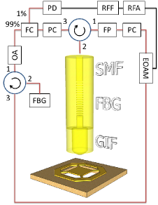
The optical ring cavity (ORC) is schematically depicted by Fig. 1. Optical gain is generated by a C-band Erbium-doped fiber optical amplifier (OA), and loss in the ORC is controlled by adjusting the direct voltage applied to the electro-optical amplitude modulator (EOAM). The state of polarization is controlled using two polarization controllers (PCs) and a fiber polarizer (FP). A fiber Bragg grating (FBG) Hill_1263 provides optical filtering. The optical signal is detected by a photodetector (PD) connected to a radio frequency filter (RFF) and a radio frequency amplifier (RFA), which can generate a feedback signal applied to the radio frequency port of the EOAM. Note that feedback signal is applied to the EOAM only for performing the measurements presented in Fig. 2 below.
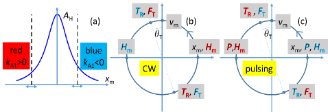
The effect of modulation (either by the moving mirror or by the EOAM) on the state of the ORC is discussed below. In the limit of small modulation amplitude the effect of noise cannot be disregarded, as was shown in Gordon_103901 . The ORC optical intensity is expressed as , where is the average intensity, is the spacing between angular frequencies of the ORC modes, is time and the function is expressed as a sum over all contributing modes of the ORC , where is the number of ORC modes within the FBG filtering band, and the positive and the real are the amplitude and phase, respectively, of the ’th ORC mode. Consider an amplitude modulation applied to the ORC. When fluctuations in modes’ amplitudes can be disregarded the evolution of the phases is governed by a set of coupled Langevin equations given by Gordon_103901
| (1) |
where the terms proportional to the modulation amplitude represent the contribution of modulation-generated sidebands of neighboring modes, and the terms represent white noise satisfying correlation relations given by , where is a constant. The main source of noise in the current experiment is quantum noise of the OA Giles_271 . In term of the Hamiltonian , which is given by , Eq. (1) can be expressed as . In steady state the probability distribution is given by , where is the partition function Risken_Fokker-Planck . In the limit of weak noise the following holds , where , and thus the phase correlation function is given by . Using these results one finds that in the limit of weak modulation amplitude , where the nicknamed comb function , which is given by
| (2) |
represents a periodic train of pulses having linewidth given by , and the averaged value of is unity for any given .
In the other extreme of relatively large modulation amplitude optical noise can be approximately disregarded. Consider a Gaussian optical pulse Kuizenga_694 having amplitude circulating inside the ORC, where is a complex constant, , determines the width of the pulse, represents a linear chirp, the real is the optical angular frequency and is time. The effect of each of the lump elements integrated into the ORC on the mode shape is characterized by either a time-like or a frequency-like Möbius transformation Nakazawa_1075 . For a frequency-like transformation characterized by the parameter one has , i.e. and , whereas for a time-like transformation characterized by the parameter one has , i.e. and . For both cases . Concatenating a time-like transformation with parameter , and a frequency-like transformation with parameter yields a Möbius transformation with coefficients , , and , where .
Two cases of mode locking are discussed below, one is based on the EOAM and the other on the moving mirror. The effect of both elements is characterized by a time-like transformation with a parameter . Both OA and FBG optical filter give rise to a frequency-like transformation. The magnitude of the parameter can be expressed in terms of an effective optical wavelength band using the relation , where is the speed of light in vacuum, is the fiber mode effective refractive index and is the optical wavelength. For the OA in the current experiment , whereas for the FBG , and thus to a good approximation the transformation parameter can be evaluated by disregarding the effect of the OA. For both methods of mode locking that are employed in the current experiment the dimensionless parameter is at most about . When it is convenient to represent the discrete Möbius transformation by a continuous differential equation of the normalized pulse parameter . To lowest nonvanishing order in and one finds that evolves according to , where , and is the ORC period time. Out of the two fixed points , only the one having a positive real value is stable. The solution is given by , where is a constant.
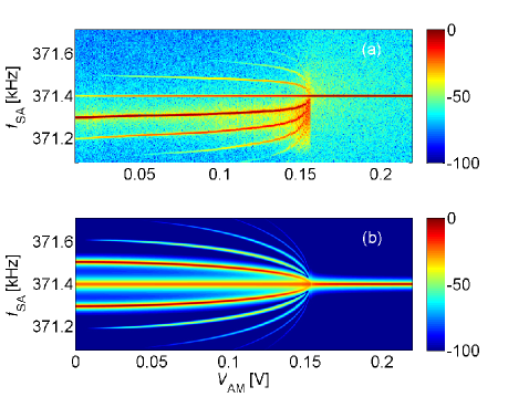
Mode locking based on the EOAM is explored without integrating the mechanical mirror. This is done by placing the optical fiber (which is connected to a piezoelectric positioner) above a pad near the trampoline. The pad, which is made of the same aluminum and silicon nitride layers (as the suspended mirror), serves as a static mirror. In this mode of operation active mode locking can be induced by driving the EOAM at a frequency close to the ORC frequency . In addition pulses can be obtained by the method of regenerative mode locking (RGML) Huggett_186 ; Levy_148 , in which the PD signal generates a feedback signal driving the EOAM (see Fig. 1). The phase of the pulses generated by RGML can be locked by simultaneously driving the EOAM at a frequency close to the ORC frequency . This is demonstrated in Fig. 2(a), which shows a color-coded plot of the spectral density (measured using a spectrum analyzer) of the PD signal as a function of the voltage amplitude of a modulation signal at a fixed frequency of applied to the EOAM. Synchronization occurs in the region . In the unlocked region, multiple side bands emerge via a continuous transition. Such side band structure is consistent with the pulse remaining synchronized with the modulation for extended periods of time, interlaced by rapid “phase slip” events. Unlocking can be well approximated by solving the equation of motion for the relative phase between the pulsing oscillation and the applied modulation, given by Strogatz_Nonlinear ; Buks_032202
| (3) |
where is a normalized detuning, the coefficient is given by (i.e. at the onset of synchronization) and is a dimensionless time variable. The solution of Eq. (3) in the region can be expressed in terms of the comb function that is defined by Eq. (2) as , where and the phase is given by Buks_032202 . The resulting spectrum is shown in Fig. 2(b).
The effect of the mechanical mirror is explored by studying two dynamical instabilities, self-excited oscillation (SEO) (see Fig. 3) and mechanical mode locking (MML) (see Fig. 4). For studying SEO the ORC frequency is not tuned close to the mechanical frequency , whereas the MML measurements are performed after adjusting the total length of the ORC to satisfy the condition . As was mentioned above, for both cases no feedback signal is applied to the EOAM.
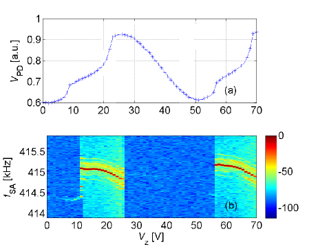
Let be the total length of the optical cavity that is formed between the fiber’s tip and the mirror. This cavity is henceforth referred to as the short cavity (SC), to avoid confusion with the much longer fiber ORC. The length can be controlled by adjusting the voltage that is applied to one of the piezoelectric motors moving the fiber. The plot shown in Fig. 3(a) presents the measured averaged PD voltage as a function of . The two local minima points of (obtained with and , respectively) represent two optical resonances of the SC (i.e. the SC length is shortened by by increasing the voltage from the value to the value ). The spectral density of the PD signal (measured using a spectrum analyzer) is shown in Fig. 3(b). The intense spectral peak that is observed in the regions and occurs due to mechanical SEO.
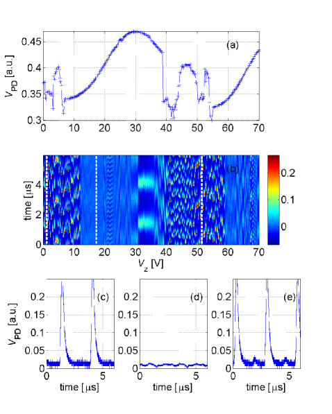
The response of the system is next explored in the region where [ is tuned to this value by adjusting the length of the ORC to the value , where for the mechanical mirror used for these measurements]. The accuracy of this procedure is typically about . The measured averaged PD voltage as a function of is shown in Fig. 4(a). The color-coded plot in Fig. 4(b) shows time traces measured by an oscilloscope connected to the PD. The time traces presented in Fig. 4(c-e) are obtained for the values , and , respectively [these values are indicated by overlaid white dotted lines in Fig. 4(b)]. The pulses shown in Fig. 4 are attributed to mirror motion that effectively generates modulation at the frequency of the mechanical oscillation. From the measured linewidth of the pulses and the relation one finds that the modulation amplitude for the narrowest peaks seen in Fig. 4. Note that, contrary to the case of SEO that is observed with red detuning (see Fig 3), the MML shown in Fig. 4 is obtained mainly with blue detuning.
Both effects of SEO and MML are attributed to bolometric optomechanical coupling. Consider an optical cavity with a movable mirror having mass , intrinsic mechanical angular frequency and an intrinsic mechanical damping rate . It is assumed that the angular resonance frequency of the mechanical resonator depends on the temperature of the suspended mirror. For small deviation of from the base temperature (i.e. the temperature of the supporting substrate) it is taken to be given by , where is a constant. Furthermore, to model the effect of thermal deformation Metzger_133903 it is assumed that a temperature dependent force given by , where is a constant, acts on the mechanical resonator. The mechanical oscillator’s equation of motion is given by , where an overdot denotes differentiation with respect to time. Intrinsic mechanical nonlinearities of the mirror are disregarded, i.e. it is assumed that nonlinear behavior exclusively originates from bolometric optomechanical coupling.
The time evolution of the relative temperature is governed by the thermal balance equation , where is proportional to the optically-induced heating power and is the thermal decay rate. The relative phase between heating and relative temperature for a steady state solution of the thermal balance equation is , where . The heating term (which is proportional to the intra-cavity optical power incident on the suspended mirror) is expressed as , where is the optical intensity. To second order in the mechanical displacement the optical absorption coefficient of the mirror is expressed as . The dependency of on the mechanical displacement originates from interference in the SC that is formed between the fiber’s tip and the mechanical mirror (note that the length of the SC is much shorter than the coherence length , where is the filtering bandwidth of the FBG). Note that the finesse of the SC is by far sufficiently low to allow disregarding retardation in the response of the SC to mechanical displacement.
The effect of the bolometric coupling on the dynamics of the optomechanical cavity has been extensively studied before for the case where light with a constant intensity is externally injected Metzger_1002 ; Jourdan_et_al_08 ; Marino&Marin2011PRE ; Metzger_133903 ; Restrepo_860 ; Liberato_et_al_10 ; Marquardt_103901 ; Paternostro_et_al_06 ; Yuvaraj_430 ; Zaitsev_046605 . Most results of this analysis are applicable for the SEO measurements shown in Fig. 3, for which the ORC frequency and the mechanical frequency are incommensurable. On the other hand, when the detuning between the ORC and mechanical frequencies is sufficiently small, the motion-induced modulation may have a significant effect on the intra-cavity optical intensity , as is demonstrated by the MML measurements shown in Fig. 4.
In the limit of small mechanical displacement the main effect of the optomechanical coupling originates from two terms of both oscillating at the mechanical frequency, the first one is due to motion-induced oscillation of the absorption , and the second one is due to motion-induced modulation in the optical intensity [see Eq. (2)]. The effect of both terms can be taken into account by replacing the mechanical angular frequency and mechanical damping rate by effective values given by
| (4) | ||||
| (5) |
In both regions of SEO and MML the damping rate becomes negative, and consequently the system becomes unstable. Nonlinear corrections to Eqs. (4) and (5) can be evaluated by taking into account both the parametric term proportional to and the second order absorption term proportional to Zaitsev_1589 . Note, however, that these nonlinear terms are not needed for determining the threshold of both SEO and MML. The term represents the contribution of the average value of the optical intensity Zaitsev_1589 , whereas the contribution of the optical intensity component oscillating at the mechanical frequency is represented by the term . When the detuning between the ORC and mechanical frequencies is negligibly small is found to be given by [see Eq. (2)], whereas the term can be disregarded when and are incommensurate.
The dominant contribution to the effective noise parameter originates from quantum noise of the OA, which has a noise figure given by , where is the small signal gain and is the population inversion parameter Giles_271 . When thermal occupation of the optical modes is negligibly small the effective noise parameter is given by , where is a typical mode damping rate (dominated by both insertion loss of the EOAM and radiation loss of the SC), and where is the averaged photon number per mode for the measurements presented in Fig. 4, and thus for this case (note that is related to the power delivered by the OA by , where ). The fact that is demonstrated by the experimental observations that MML occurs in almost the entire region of blue detuning (see Fig. 4), whereas for the same optical gain SEO occurs only in a partial region of red detuning (see Fig. 3).
Note that the sign of the term is opposite to the sign of . As is explained in the caption of Fig. 5, this can be attributed to the fact that pulses generated by mode locking hit the mirror when the displacement-dependent optical absorption obtains its minimum value. Both added damping rates and [see Eq. (5)] depend on the detuning of the SC. When the SC is blue (red) detuned the absorption coefficient in Eq. (5) is negative (positive) Baskin_563 (note that it is assumed that positive displacement is in the outwards direction and that the cavity length is decreased when the piezoelectric motor voltage is increased). Aluminum has a thermal expansion coefficient higher than both silicon and silicon-nitride, and consequently it is expected that and . Thus, for the device under study here it is expected that when the SC is red detuned [see Eq. (5)]. This behavior is demonstrated by the SEO shown in Fig. 3. On the other hand, when the SC is blue detuned. This is consistent with the experimental observation that MML occurs mainly with blue detuning (see Fig. 4).
In summary, we find that mode locking can be obtained by integrating gain medium into an optomechanical cavity. The threshold optical power for MML is found to be significantly lower than the corresponding value for SEO. Future study will explore applications of MML for sensing. For example, Braginsky has proposed a device called a speed meter, which allows monitoring a classical force acting on a mechanical resonator with sensitivity that can exceed the so-called standard quantum limit Braginsky_251 ; Braginskii_27 . In the steady state of MML the pulses hit the mirror when its velocity nearly vanishes, and thus the off reflected pulses mainly carry information about the velocity (rather than the position) of the mirror, therefore a sensor based on MML may serve as a sensitive speed meter.
We thank Moshe Horowitz and Baruch Fischer for useful discussion. Argonne National Laboratory’s contribution is based upon work supported by Laboratory Directed Research and Development (LDRD) funding from Argonne National Laboratory, provided by the Director, Office of Science, of the U.S. Department of Energy under Contract No. DE-AC02-06CH11357.
References
- (1) V. Braginsky and A. Manukin, “Ponderomotive effects of electromagnetic radiation”, Soviet Physics JETP, vol. 25, pp. 653, 1967.
- (2) K. Hane and K. Suzuki, “Self-excited vibration of a self-supporting thin film caused by laser irradiation”, Sensors and Actuators A: Physical, vol. 51, pp. 179–182, 1996.
- (3) S. Gigan, H. R. Böhm, M. Paternostro, F. Blaser, J. B. Hertzberg, K. C. Schwab, D. Bauerle, M. Aspelmeyer, and A.Zeilinger, “Self cooling of a micromirror by radiation pressure”, Nature, vol. 444, pp. 67–70, 2006.
- (4) C. H. Metzger and K.Karrai, “Cavity cooling of a microlever”, Nature, vol. 432, pp. 1002–1005, 2004.
- (5) T. J. Kippenberg and K. J. Vahala, “Cavity optomechanics: Back-action at the mesoscale”, Science, vol. 321, no. 5893, pp. 1172–1176, Aug 2008.
- (6) C. Metzger I. Favero, S. Camerer, D. Konig, H. Lorenz, J. P. Kotthaus, and K. Karrai, “Optical cooling of a micromirror of wavelength size”, Appl. Phys. Lett., vol. 90, pp. 104101, 2007.
- (7) Florian Marquardt and Steven M. Girvin, “Optomechanics”, Physics, vol. 2, pp. 40, May 2009.
- (8) M. Poot and H. S.J. van der Zant, “Mechanical systems in the quantum regime”, Phys. Rep., vol. 511, pp. 273–335, 2012.
- (9) G. Jourdan, F. Comin, and J. Chevrier, “Mechanical mode dependence of bolometric backaction in an atomic force microscopy microlever”, Phys. Rev. Lett., vol. 101, pp. 133904, Sep 2008.
- (10) Francesco Marino and Francesco Marin, “Chaotically spiking attractors in suspended-mirror optical cavities”, Phys. Rev. E, vol. 83, pp. 015202, Jan 2011.
- (11) C. Metzger, M. Ludwig, C. Neuenhahn, A. Ortlieb, I. Favero, K. Karrai, and F. Marquardt, “Self-induced oscillations in an optomechanical system driven by bolometric backaction”, Phys. Rev. Lett., vol. 101, pp. 133903, Sep 2008.
- (12) J. Restrepo, J. Gabelli, C. Ciuti, and I. Favero, “Classical and quantum theory of photothermal cavity cooling of a mechanical oscillator”, Comptes Rendus Physique, vol. 12, pp. 860–870, Nov 2011.
- (13) S. D. Liberato, N. Lambert, and F. Nori, “Quantum limit of photothermal cooling”, arXiv:1011.6295, Nov 2010.
- (14) Florian Marquardt, J. G. E. Harris, and S. M. Girvin, “Dynamical multistability induced by radiation pressure in high-finesse micromechanical optical cavities”, Phys. Rev. Lett., vol. 96, pp. 103901, 2006.
- (15) M. Paternostro, S. Gigan, M. S. Kim, F. Blaser, H. R. Böhm, and M. Aspelmeyer, “Reconstructing the dynamics of a movable mirror in a detuned optical cavity”, New J. Phys., vol. 8, pp. 107, Jun 2006.
- (16) D. Yuvaraj, M. B. Kadam, Oleg Shtempluck, and Eyal Buks, “Optomechanical cavity with a buckled mirror”, JMEMS, vol. 22, pp. 430, 2013.
- (17) S. Zaitsev, A. K. Pandey, O. Shtempluck, and E. Buks, “Forced and self-excited oscillations of optomechanical cavity”, Phys. Rev. E, vol. 84, pp. 046605, 2011.
- (18) Oren Suchoi, Lior Ella, Oleg Shtempluk, and Eyal Buks, “Intermittency in an optomechanical cavity near a subcritical hopf bifurcation”, Physical Review A, vol. 90, no. 3, pp. 033818, 2014.
- (19) Herman A Haus, “Mode-locking of lasers”, IEEE Journal of Selected Topics in Quantum Electronics, vol. 6, no. 6, pp. 1173–1185, 2000.
- (20) Sumei Huang and GS Agarwal, “Enhancement of cavity cooling of a micromechanical mirror using parametric interactions”, Physical Review A, vol. 79, no. 1, pp. 013821, 2009.
- (21) GS Agarwal and Sumei Huang, “Strong mechanical squeezing and its detection”, Physical Review A, vol. 93, no. 4, pp. 043844, 2016.
- (22) Chang-Sheng Hu, Zhen-Biao Yang, Huaizhi Wu, Yong Li, and Shi-Biao Zheng, “Twofold mechanical squeezing in a cavity optomechanical system”, Physical Review A, vol. 98, no. 2, pp. 023807, 2018.
- (23) Xin-You Lü, Ying Wu, JR Johansson, Hui Jing, Jing Zhang, and Franco Nori, “Squeezed optomechanics with phase-matched amplification and dissipation”, Physical review letters, vol. 114, no. 9, pp. 093602, 2015.
- (24) Sebastian Pina-Otey, Fernando Jiménez, Peter Degenfeld-Schonburg, and Carlos Navarrete-Benlloch, “Classical and quantum-linearized descriptions of degenerate optomechanical parametric oscillators”, Physical Review A, vol. 93, no. 3, pp. 033835, 2016.
- (25) Sumei Huang and GS Agarwal, “Normal-mode splitting in a coupled system of a nanomechanical oscillator and a parametric amplifier cavity”, Physical Review A, vol. 80, no. 3, pp. 033807, 2009.
- (26) Michael R Vanner, Igor Pikovski, Garrett D Cole, MS Kim, Č Brukner, Klemens Hammerer, Gerard J Milburn, and Markus Aspelmeyer, “Pulsed quantum optomechanics”, Proceedings of the National Academy of Sciences, vol. 108, no. 39, pp. 16182–16187, 2011.
- (27) VB Braginskii, Yu I Vorontsov, and F Ya Khalili, “Optimal quantum measurements in detectors of gravitation radiation”, JETP Lett, vol. 27, no. 5, 1978.
- (28) Juha T Muhonen, Giada R La Gala, Rick Leijssen, and Ewold Verhagen, “State preparation and tomography of a nanomechanical resonator with fast light pulses”, arXiv:1812.09720, 2018.
- (29) WC Henneberger and HJ Schulte, “Optical pulses produced by laser length variation”, Journal of Applied Physics, vol. 37, no. 5, pp. 2189–2189, 1966.
- (30) PW Smith, “Phase locking of laser modes by continuous cavity length variation”, Applied Physics Letters, vol. 10, no. 2, pp. 51–53, 1967.
- (31) RI Baranov and Yu M Shirokov, “Electromagnetic field in an optical resonator with a movablemirror”, Sov. Phys. JETP, vol. 53, pp. 2123, 1967.
- (32) Kenneth O Hill and Gerald Meltz, “Fiber bragg grating technology fundamentals and overview”, Journal of lightwave technology, vol. 15, no. 8, pp. 1263–1276, 1997.
- (33) Ariel Gordon and Baruch Fischer, “Phase transition theory of many-mode ordering and pulse formation in lasers”, Physical review letters, vol. 89, no. 10, pp. 103901, 2002.
- (34) C Randy Giles and Emmanuel Desurvire, “Modeling erbium-doped fiber amplifiers”, Journal of lightwave technology, vol. 9, no. 2, pp. 271–283, 1991.
- (35) Hannes Risken, The Fokker-Planck Equation: Methods of Solution and Applications, Springer, 1996.
- (36) D Kuizenga and A Siegman, “Fm and am mode locking of the homogeneous laser-part i: Theory”, IEEE Journal of Quantum Electronics, vol. 6, no. 11, pp. 694–708, 1970.
- (37) Masataka Nakazawa, Hirokazu Kubota, Akio Sahara, and Kohichi Tamura, “Time-domain abcd matrix formalism for laser mode-locking and optical pulse transmission”, IEEE Journal of Quantum Electronics, vol. 34, no. 7, pp. 1075–1081, 1998.
- (38) GR Huggett, “Mode-locking of cw lasers by regenerative rf feedback”, Applied Physics Letters, vol. 13, no. 5, pp. 186–187, 1968.
- (39) Etgar C Levy, Moshe Horowitz, and Curtis R Menyuk, “Modeling optoelectronic oscillators”, JOSA B, vol. 26, no. 1, pp. 148–159, 2009.
- (40) S.H. Strogatz, Nonlinear Dynamics and Chaos: With Applications to Physics, Biology, Chemistry and Engineering, Perseus Books Group, 2000.
- (41) Eyal Buks and Ivar Martin, “Self-excited oscillation and synchronization of an on-fiber optomechanical cavity”, Phys. Rev. E, vol. 100, pp. 032202, Sep 2019.
- (42) S. Zaitsev, O. Gottlieb, and E. Buks, “Nonlinear dynamics of a microelectromechanical mirror in an optical resonance cavity”, Nonlinear Dyn., vol. 69, pp. 1589–1610, 2012.
- (43) Ilya Baskin, D.Yuvaraj, Gil Bachar, Keren Shlomi, Oleg Shtempluck, and Eyal Buks, “Optically induced self-excited oscillations in an on-fiber optomechanical cavity”, JMEMS, vol. 23, pp. 563–569, 2014.
- (44) VB Braginsky and F Ja Khalili, “Gravitational wave antenna with qnd speed meter”, Physics Letters A, vol. 147, no. 5-6, pp. 251–256, 1990.