A Novel PHY Layer Approach for Enhanced Data Rate in LoRa using Adaptive Symbol Periods
Abstract
LoRaWAN has emerged as one of the promising low-power wide-area network technologies to enable long-range sensing and monitoring applications in Internet of Things. The LoRa physical layer used in LoRaWAN suffers from low data rates and thus increases packet duration. In a dense LoRaWAN network scenario with simple media access protocol like ALOHA, the packet collision probability increases with increase in packet duration. This degrades over-all network throughput because of increased re-transmissions of collided packets. Any increase in data rate directly reduces the packet duration. Thus, in this paper, we have proposed a novel approach to enhance the data rate in LoRa communication system by using adaptive symbol periods in physical layer. To the best of our knowledge, this is the first attempt at using adaptive symbol periods to enhance data rate of the LoRa system. The trade-off of the proposed approach in terms of required symbol overhead and degradation in bit error rate performance due to symbol period reduction has also been analysed. We have shown that for reduction factor , the data rate directly increases times.
Index Terms:
Internet of Things, Low-Power Wide-Area Network, LoRa, Chirp Spread Spectrum, Physical LayerI Introduction
Low-power wide-area network (LPWAN) protocols play an important role in Internet of Things (IoT) by providing long-range communication while keeping transmission energy low [1] [2]. This translates to increased lifetime of several years for battery operated IoT devices. LPWAN also suffers from low data rates below just a few kbps. This small data rate is suitable for applications specific to asset tracking, structural health monitoring, energy metering in smart grid, smart city infrastructure, etc.
LPWAN enables a large number of IoT devices to be deployed in a small area, making up a very dense IoT network. These devices are supposed to be constrained in hardware capabilities as well as energy budget for data transmission. Thus, here arises requirement for a highly sophisticated and advanced media access control (MAC) protocol to accommodate large number of devices in a dense network. However, due to processing and energy constraints, MAC protocol being used in such networks is often as simple as ALOHA or time division multiple access (TDMA).
LoRaWAN is one of the LPWAN technologies, which has gathered much attraction in recent years. Its specifications are maintained by LoRa Alliance [3][4]. LoRa is the physical layer modulation scheme used in the LORAWAN. It has been patented by Semtech Corporation [5]. Other LPWAN technologies which are also actively being used are NBIoT, SigFox, etc. [6]. In this paper, we focus on LoRaWAN technology to improve its data rate by adaptive symbol period reduction of LoRa modulation scheme. This further improves the collision performance and thus improves overall network throughput.
Chirp spread spectrum (CSS) [7] is used in the LoRa physical layer because of its resilience to noise and good sensitivity [8]. The main principle of CSS is to use of much larger transmission bandwidth than required. Due to this, the receiver can achieve higher sensitivity and recover signals over a longer distance even at poor SNR conditions.
However, LoRa suffers from very low data rates, thus increasing the packet duration. Due to use of ALOHA based MAC protocol, the higher packet duration translates to increase in the packet collision probability and thus degradation of network throughput [9].
In this paper, we have proposed a novel approach for data rate enhancement using adaptive symbol periods. Increased data rate decreases the packet duration. This helps in achieving better collision performance as the individual packet duration decreases. Since the transmission energy is also directly proportional to packet duration, reduction in packet duration can also save transmission energy of the end device. To the best of our knowledge, this kind of approach has never been explored in the existing literature. Therefore this is the first time adaptive symbol period in LoRa for data rate enhancement has been proposed.
Rest of the paper is organized as follows. In Section II, we provide a brief introduction to a few basics of LoRaWAN which are important to understand our proposed approach. LoRa physical layer is explained in detail in Section III. The proposed approach of data rate enhancement in LoRa using adaptive symbol period is explained in Section IV. Results and discussion regarding merits and trade-offs of the proposed approach are given in Section V. Conclusion of the paper is given in Section VI.
II Primer To LoRaWAN
LoRaWAN network consists of end devices communicating with a central gateway operating in a star topology [3]. Based on the device transmission and reception capabilities, LoRaWAN specification [4] has defined three categories of devices.
-
•
Class A: After each uplink transmission, devices of this category can receive downlink messages in two short reception windows. Other than these times, the device stays in sleep mode to reduce the energy consumption. Thus, these devices can be operated with a battery and can last for several years.
-
•
Class B: Devices in this category have a predetermined periodic reception window. These devices can receive periodic beacons from gateway server and thus, can be controlled from gateway with latency equal to the beacon interval. These devices have higher energy consumption than Class A devices.
-
•
Class C: Devices of this category have their reception always on, except for the time of transmission. These devices do not have any sleep window and thus, their energy consumption can not be optimized. However, because of always active reception, these devices offer the minimum downlink latency.
Since an IoT device needs to have lower energy consumption and increased battery lifetime, Class A devices are more popular and more widely used than other classes. These devices provide battery lifetime of several years along with a very wide communication range. This makes these devices very much suitable for IoT applications.
However, LoRaWAN network can also have class C devices, which are not as energy constrained as class A and class B devices. For such devices, improving data rate can be more beneficial towards mitigating the network congestion, than optimizing transmission power. This is further discussed in section V.
II-A LoRa Packet Structure
LoRa physical layer packet consists of preamble, header and payload symbols. The preamble serves the purpose of timing synchronization for correct recovery of the symbols. It consists of a sequence of unmodulated upchirp symbols, followed by 2.25 symbols of unmodulated downchirp for notifying the receiver of start of header and payload.
After preamble, header symbols are transmitted which contain information about length of packet, coding rate and presence of CRC of payload along with its own CRC. In Implicit Header mode, the header can be removed to reduce packet length and decrease packet duration. In this case, both transmitter and receiver need to be in agreement of these parameters. Header is followed by payload symbols and payload CRC.
II-B LoRaWAN Transmission Options
According to LoRaWAN specification [4], there are five configuration parameters which can be adjusted to optimize the network. These parameters are as following,
-
•
Carrier Frequency (CF): CF is the center frequency of the frequency variation in the chirp signal. According to specification, CF can be chosen from 137 MHz to 1020 MHz. Since some parts of these frequencies may be unavailable in different regions of the world due to licensing, it is advised to use frequencies according to the region of operation.
-
•
Bandwidth (BW): Bandwidth is the difference between minimum and maximum frequencies of the chirp signal. According to specifications, BW of 125 kHz, 250 kHz or 500 kHz can be used. Higher BW gives higher data rate, but at the same time it also reduces the receiver sensitivity.
-
•
Spreading Factor (SF): According to specifications, SF can be chosen from 7 to 12. SF determines the number of chips per symbol which is given as . Higher SF increases the sensitivity of receiver against noise and thus range of communication. But increasing SF by one also doubles the time per symbol, and thus halves the symbol transmission rate.
-
•
Transmission Power: The transmission power of the LoRa radio module can be varied in steps from -4 dB to 20 dBm. The adaptive variation of transmission power helps in reducing transmission energy at battery operated end device and thus extending its lifetime.
-
•
Coding Rate (CR): To improve bit error rate (BER) performance in presence of burst interference, a forward error correction (FEC) scheme is used. According to LoRaWAN specifications, CR of 4/5, 4/6, 4/7 or 4/8 can be used. CR of 4/8 offers highest redundancy and thus highest resilience to noise, but also doubles the time-on-air compared to the un-coded packet.
II-C Adaptive Data Rate (ADR) Mechanism
ADR mechanism is an important part of LoRaWAN specification [10]. It enables the system to optimize spreading factor (SF) and transmission power (TP) of all end devices in order to increase reliability of communication as well as optimize energy consumption of battery powered end devices[11].
If an end device does not receive any acknowledgement on downlink after multiple consecutive uplink transmissions, then it assumes that its transmissions are not being decoded properly at the receiver, i.e. the connection has been lost. The end device tries to adapt to this change by gradually increasing its TP to the maximum possible. After maximum possible TP has been achieved and still no acknowledgment is being received, the end device increments its SF by 1. The end devices thus change their SF & TP values to establish a reliable uplink. This may not be an efficient communication link as energy consumption of end device increases as TP increases [12].
Thus, there is also provision for the LoRa network server to monitor uplink quality and command end devices to change their SF & TP values in order to maximize the network throughput.
The uplink quality of each packet of each end device is stored in history of network server. If the uplink quality for recent packets of an end device is found to be much better than the minimum required, the network server can notify that end device to reduce its transmission power and SF value. The purpose of this adjustment is to ensure that the signal-to-noise ratio (SNR) of uplink is not too much greater than the minimum required.
The reduction in SF increases data rate and thus decreases the transmission time of packet (time-on-air). Reduction in TP reduces transmission energy and thus increases lifetime of the battery operated end device.
III Lora Physical Layer
Lora physical layer consists modulation of symbols, transmission of modulated signal and demodulation of symbols by the receiver. LoRa physical layer uses CSS based modulation technique [13]. A chirp is a sinusoidal signal whose frequency is linearly varying over time. Thus it is also called as linear frequency modulated (LFM) signal. Since the signal is spread over a wide bandwidth, the sensitivity at the receiver increases and the signal with poor SNR can also be recovered successfully.
III-A LoRa Modulation Scheme
Assume the minimum and maximum instantaneous frequencies of the chirp to be and Hertz. Thus bandwidth of chirp becomes Hertz. Thus for time per symbol , the rate of increase of frequency of an upchirp can be written as . For downchirp, the rate of decrease of frequency can be written as () .
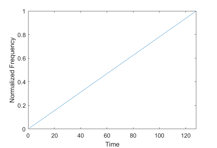
The basechirp used for modulation of payload symbols is an upchirp, i.e. a sinusoidal signal whose frequency is linearly increasing from to Hz as shown in Fig. 1(a). Thus the base upchirp and its frequency variation can be written as following.
| (1) |
| (2) |
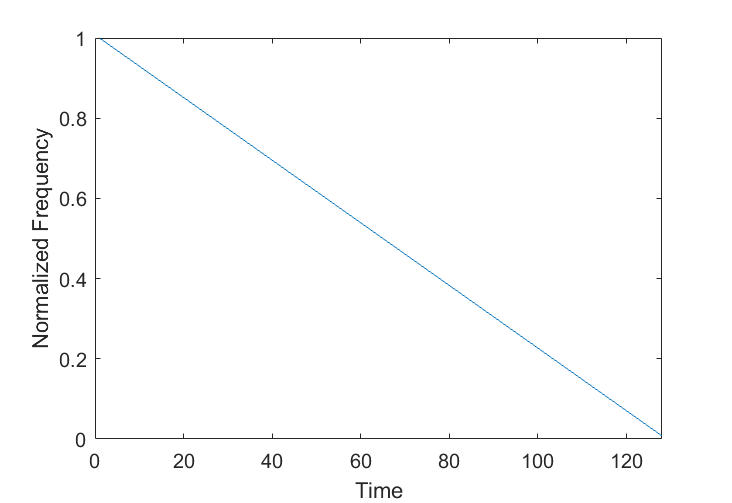
Similarly, a downchirp is a sinusoidal signal whose frequency is linearly decreasing from to Hz as shown in Fig. 1(b). Thus, the downchirp and its frequency variation can be written as following.
| (3) |
| (4) |
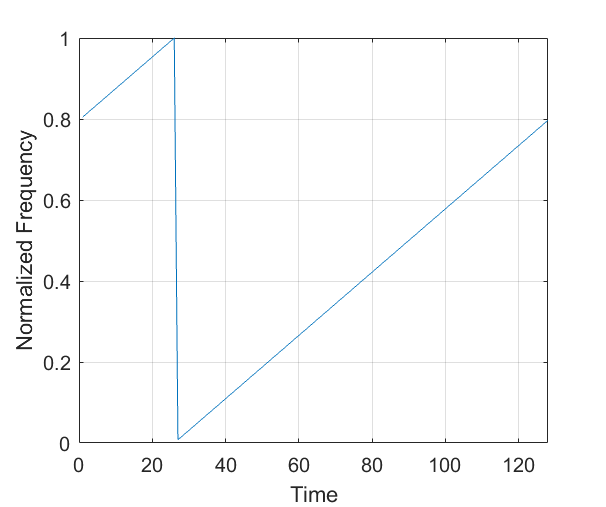
For modulation, each LoRa symbol is encoded as a cyclic shift in the base upchirp. It can also be viewed as frequency shift chirp modulation [8] as it works on the principle of modulating data symbol in terms of cyclic shifts of the upchirp. Spreading Factor determines the number of all possible symbols which is given as . In other words, for a LoRa symbol , this can be written as . Thus, in the total time period for one symbol , one of possible cyclic shifts needs to be used depending on the LoRa symbol being modulated. The cyclic shifts are implemented in steps of .
Let be the cyclic shift corresponding to symbol . Therefore, corresponding to symbol , the cyclic shifted upchirp and its frequency variation (refer Fig.2) can be written as following.
| (5) |
| (6) |
The modulated upchirp corresponding to each symbol is transmitted for time period . Thus the total transmission time for symbols, i.e. time-on-air becomes .
III-B LoRa Demodulation Scheme
In literature as well as in practice, the orthogonality of LoRa chirp signals has been well established and tested. Thus at the receiver, the best way to detect the modulated symbol i.e. the cyclic shift in the modulated upchirp is using an optimum filter matched to the frequency spectrogram of base upchirp.
In frequency domain, upchirp and downchirp are time mirrored forms of each other. Therefore, correlation with an upchirp is same as convolution with a downchirp. Since convolution in frequency domain is same as multiplication in time domain, the whole process of symbol detection simplifies to a simple multiplication of incoming signal with a downchirp. In literature, this is also referred as De-Chirping of signal. The product of modulated upchirp and downchirp can be written as
| (7) |
When sampled at sampling frequency of Hz, the terms and in the above equation vanish and therefore can be neglected in the analysis.
After the received signal is de-chirped by multiplying with a downchirp, the product gives a complex sinusoidal signal with frequency proportional to the cyclic time shift in the modulated upchirp.
This frequency can be calculated by taking point Inverse Fast Fourier Transform (IFFT) of the product. The symbol can be found by searching for the index of peak in the IFFT magnitude.
The margin by which the magnitude of this maximum peak in the IFFT rises above the noise-floor is also a measure of SNR. If the SNR is good, the peak is higher with respect to noise-floor and can be easily detected by the receiver. Similarly, if the SNR is poor, the peak is just above the noise-floor, making it difficult to be detected.
IV The Proposed Approach for Adaptive Symbol Period in LoRa PHY Layer
Our intuition to reduce the symbol period comes from the fact that when SNR is high, some samples in the received modulated upchirp can be strategically dropped without loosing ability to detect the required peak in IFFT.
In the proposed approach, for each symbol of payload, instead of transmitting the corresponding cyclic shifted upchirp for the total symbol period , it is transmitted only for period , where is the reduction factor.
| (8) |
The transmitter then starts to transmit next symbol’s upchirp after time period . Thus the modulated upchirp corresponding to each symbol is transmitted for time duration only, where .
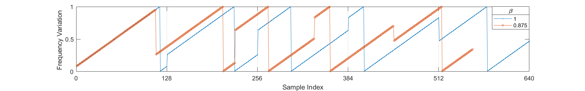
As seen in Fig. 3, corresponds to symbol period samples and corresponds to reduced symbol period samples. Thus, for the same 5 symbols, the proposed approach requires 560 samples compared to 640 original samples. The proposed approach with improves symbol rate times the original symbol rate.
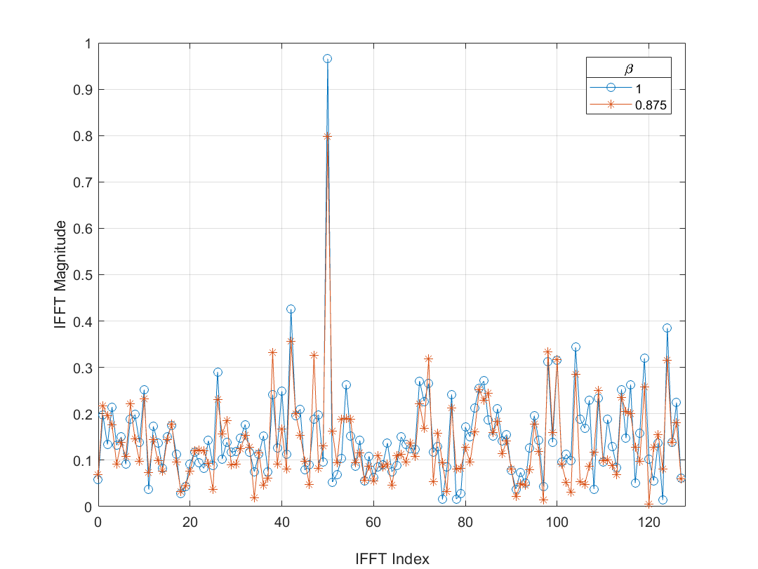
In Fig. 4 & Fig. 5, IFFT magnitude of de-chirped signal for a single LoRa symbol is plotted for values of & . The simulations are performed assuming an additive white Gaussian noise of . It can be seen that the lower reduction factor also decreases symbol energy, thus degrading signal-to-noise ratio. This decreases the detection probability of correct symbol for lower values of reduction factor.
Our solution is to use adaptive reduction factor depending on the SNR conditions of the communication link. The receiver needs to know value of the adaptive reduction factor to determine in order to correctly decode the symbols. We address this issue by introducing an extra symbol in the header part of the packet. This symbol is to convey information about value used by transmitter for subsequent payload symbols.
Since preamble and header parts are critical for packet detection as well as frequency and time synchronization, their symbol periods should not be modified. This ensures that the preamble detection at the receiver is not degraded due to the proposed approach.
For decoding procedure for the proposed approach, receiver can use information about from header to calculate . Accordingly, after end of header, consecutive received signal blocks of period can be used for decoding corresponding symbols of payload.
Therefore, at the receiver, is multiplied by truncated downchirp i.e. .
| (9) |
The element-by-element product of and is equivalent to truncated at .
| (10) |
This truncation of samples in the product does not affect its frequency. Thus after IFFT, we can detect the correct maximum peak corresponding to symbol. The only change is decrease in magnitude of this peak, resulting in degradation of SNR. This effect on SNR can be observed in Fig. 4 & Fig. 5.
V Results and Discussion
V-A Advantages of The Proposed Approach
The proposed approach has a cascading effect on network performance. It affects multiple performance parameters of the network like energy efficiency, data rate, congestion, packet delivery rate, etc. This effect can be explained step-by-step as follows.
-
•
The proposed approach decreases the symbol period by factor . This reduction in symbol period directly increases the physical layer data rate () times.
-
•
Increase in data rate effectively decreases transmission time, i.e. time-on-air, of the packet.
-
•
Decrease in time-on-air also means a proportional decrease in transmission energy. This helps in increasing the lifetime of battery operated devices.
-
•
As packet duration and packet collisions are closely related, the proposed approach also reduces packet collision probability and thus increases packet delivery rate. Therefore it also improves the overall network throughput.

V-B Trade-off
V-B1 Degradation of SNR and increase in BER
The advantages of the proposed approach come at the cost of degradation in SNR. As shown in Fig. 4 & Fig. 5, the required peak in IFFT magnitude decreases to 80% with and to 60% for . This shows that with the decrease in the signal component degrades, contributing to higher BER. These results are for SF value 7 and SNR of -5 dB.
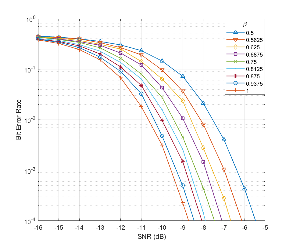
This can also be seen in bit error rate graph in Fig. 6. As a decrease in reduces symbol period and effective symbol energy, this translates to degradation of SNR at the receiver. Hence it can be seen that decrease in increases BER at the receiver.
Thus the margin, by which SNR is higher than the minimum required, should be used to determine the suitable symbol period reduction factor . This surplus SNR margin required for different values of reduction factor can be understood from Fig. 6.
Since the proposed approach depends on SNR for deciding symbol period reduction factor , the end devices which do not have SNR higher than the minimum required, should not use the proposed approach. In other words, their value should be always 1.
V-B2 Symbol Overhead
The proposed approach also has an overhead of one extra symbol in header of the packet. This symbol contains information about the reduction factor used by the transmitter for subsequent payload symbols.
For the payload of symbols, the saving in time-on-air is given as and the overhead is just one symbol of time period . Thus this overhead is negligible in case of large payloads and small beta value.
Therefore, as long as time saving in payload part is greater than 1, it can give time saving for the packet. This time saving for packet can be quantified as,
| (11) |
The subtraction of in above equation corresponds to the overhead of one symbol added in the header.
V-B3 Effect on dense network
In a dense LoRa deployment, in order to reduce collision and congestion, reducing packet duration becomes more important than optimizing transmission powers of end devices.
In the dense network scenario, some of the end devices, which have good SNR conditions, can benefit from the proposed approach and adapt their symbol period to increase their data rate. This reduces their packet duration and thus, reduces network congestion contributed by these devices to some extent. This results in decrease of collision probability and also improvement in the packet delivery rate.
V-B4 Adoption in LoRaWAN
In order to increase lifetime of the battery operated end devices, LoRaWAN uses ADR mechanism to optimizes transmission powers of end devices. But for class C devices which don’t need to have any constraint on energy consumption, data rate enhancement holds higher preference than transmission power reduction. Thus, the proposed approach can be aggressively employed on such devices to get higher data rate. This results in the reduction in transmission time of corresponding packets and thus, reduction in the network congestion.
The proposed approach gives all the improvements mentioned above, but also degrades BER at the receiver by a small margin. Thus, similar to the existing ADR mechanism in LoRaWAN, a better way can be to monitor SNR for consecutive packets and employ the proposed approach to adaptively reduce symbol period depending on additional available SNR margin over the minimum required. Therefore the LoRa end devices having good SNR can use it to their advantage and transmit their data at higher rate using the proposed approach.
VI Conclusion
In this paper, we have proposed an adaptive symbol period based approach for data rate enhancement in LoRa. The reduction in symbol period is achieved by truncation of chirp signal corresponding to LoRa payload symbol. This reduces the time-on-air of packets and therefore, mitigates packet collisions as well as network congestion. The proposed approach increases BER at the receiver by a small margin depending on reduction factor . However, it is acceptable in case of good communication link conditions having SNR much higher than the minimum required. Thus, the proposed approach can be aggressively employed in LoRa devices and the overall network performance can be improved.
Acknowledgment
This work is supported by Visvesvaraya Ph.D. Scheme, Ministry of Electronics and Information Technology (MeitY), Govt. of India and Indian Institute of Technology Hyderabad, India.
References
- [1] U. Raza, P. Kulkarni and M. Sooriyabandara, “Low power wide area networks: An overview,” IEEE Communications Surveys Tutorials, vol. 19, no. 2, pp. 855-873, 2017.
- [2] M. Centenaro, L. Vangelista, A. Zanella and M. Zorzi, “Long-range communications in unlicensed bands: The rising stars in the IoT and smart city scenarios,” IEEE Wireless Communications, vol. 23, no. 5, pp. 60–67, Oct. 2016.
- [3] LoRa Alliance. (2015). “LoRaWAN, What is it ? A technical overview of LoRa and LoRaWAN,” Nov. 2015. [Online]. Available: https://www.lora-alliance.org/portals/0/documents/whitepapers/LoRaWAN101.pd
- [4] Lorawan 1.1 specification, 2017 [online]. Available: https://lora-alliance.org/resource-hub/lorawantm-specification-vll.
- [5] F. Sforza, “Communication system,” U.S. Patent 8406275, Mar. 26, 2013. [Online]. Available: https://www.google.com/patents/US8406275
- [6] C. Goursaud and J.M. Gorce, “Dedicated Networks for IoT: PHY/MAC State of the Art and Challenges,” EAI Endorsed Trans. on Internet of Things, vol. 1, no. 1, pp. 1-11, Oct. 2015.
- [7] B. Reynders and S. Pollin, “Chirp spread spectrum as a modulation technique for long range communication,” in Proc. Symposium on Communications and Vehicular Technologies, 2016, pp. 1-5.
- [8] L. Vangelista, “Frequency Shift Chirp Modulation: The LoRa Modulation,” IEEE Signal Processing Letters, vol. 24, no. 12, pp. 1818-1821, Dec. 2017.
- [9] A. Rahmadhani and F. Kuipers, “When lorawan frames collide,” in Proc. of the 12th International Workshop on Wireless Network Testbeds, Experimental Evaluation & Characterization (ACM WiNTECH 2018), 2018. pp. 89-97.
- [10] M. Slabicki, G. Premsankar and M. D. Francesco, “Adaptive configuration of lora networks for dense iot deployments,” in Proc. NOMS IEEE/IFIP Network Operetions and Management Symposium, 2018, pp. 1–9
- [11] V. Hauser and T. Hegr, “Proposal of adaptive data rate algorithm for lorawan-based infrastructure,” in IEEE 5th International Conference on Future Internet of Things and Cloud (FiCloud), pp. 85-90, Aug. 2017.
- [12] S. Li, U. Raza and A. Khan, “How Agile is the Adaptive Data Rate Mechanism of LoRaWAN?,” in IEEE Global Communications Conference (GLOBECOM), 2018, Abu Dhabi, UAE, 2018, pp. 206-212.
- [13] AN1200.22 LoRa Modulation Basics, May 2015. [online]. Available: http://www.semtech.com/images/datasheet/an1200.22.pdf.