Empirical Feasibility Analysis for Energy Harvesting Intra-Vehicular Wireless Sensor Networks
Abstract
Vehicle electronic systems currently utilize wired networks for power delivery (from the main battery) and communication (e.g., LIN, CAN, FlexRay) between nodes. Wired networks cannot practically accommodate nodes in moving parts (e.g., tires) and with the increasing functional complexity in vehicles, they require kilometer-long harnesses, significantly increasing fuel consumption and manufacturing and design costs. As an alternative, energy harvesting intra-vehicular wireless sensor networks (IVWSN) can accommodate nodes in all locations and they obviate the need for wiring, significantly lowering costs. In this paper, we empirically analyze the feasibility of such an IVWSN framework via extensive in-vehicle measurements for communications at 2.4 GHz, ultra wideband (UWB) and millimeter wave (mmWave) frequencies together with radio frequency (RF), thermal and vibration energy harvesting. Our analyses show that mmWave performs best for short line-of-sight (LoS) links in the engine compartment with performance close to UWB for LoS links in the chassis and passenger compartments in terms of worst case signal-to-interference-and-noise-ratio. For non-LoS links, which appear especially more in the engine compartment and chassis, UWB provides the highest security and reliability. 2.4 GHz suffers heavily from interference in all compartments while UWB utilizes narrowband suppression techniques at the cost of lower bandwidth; mmWave inherently experiences very low interference due to its propagation characteristics. On the other hand, radio frequency (RF) energy harvesting provides up to 1 mW of power in all compartments. Vibration and thermal energy harvesters can supply all nodes consuming 10 mW in the engine compartment and all 5 mW nodes in the chassis. In the passenger compartment, thermal harvesting is not available due to low temperature gradients but vibration and RF sources can supply 1 mW nodes.
Index Terms:
Energy harvesting, Intra-vehicular communication, Wireless Sensor NetworksI Introduction
Electronic control systems have replaced their mechanical counterparts in modern vehicles since they can accommodate different functions with smaller design and integration cost [1]. These systems contain networks of electronic control units (ECU) and many distributed sensors and actuators with wired interconnections for power (i.e., from the vehicle battery) and communication (e.g., LIN, CAN, FlexRay [2]). With the increasing demand for more functionality on vehicles, harnesses for these systems have reached up to 4 km of wiring and are still growing; this increases fuel consumption and manufacturing and design costs. Furthermore, these wired networks cannot practically accommodate nodes in moving parts (e.g. tire pressure monitoring and Intelligent Tire [3]). A solution to these problems is converting these sensors and actuators into energy harvesting nodes which wirelessly communicate with each other and ECU s [4].
Two main barriers towards realizing these energy harvesting intra-vehicular wireless sensor network (IVWSN) are harvesting enough energy for their functionality [5], and realizing reliable and secure communication within small delay at sufficient rate. The amount of harvestable energy and communication performance vary over both the respective technologies and the locations of nodes inside the vehicle. Therefore, to assess the feasibility of the IVWSN framework, the potential of different energy harvesting and communication technologies need to be analyzed for node locations in different vehicle compartments (e.g., knock sensor in the engine, rain sensor in the body).
Existing studies on communication technologies for IVWSN have focused on RFID (915 MHz), 2.4 GHz, ultra wideband (UWB) and millimeter wave (mmWave). Experimental studies on RFID [6] and 2.4 GHz [7] have demonstrated the feasibility of communication in different vehicle compartments but power loss in passive RFID nodes and external interference into the vehicle at 2.4 GHz nodes are prohibitively large for safety-critical communications. Channel modeling studies for UWB have have demonstrated the high reliability and energy efficiency of UWB communication in all vehicle compartments. [8, 9, 10]. Comparative studies between mmWave and UWB have shown that mmWave provides better reliability for short line-of-sight links in the multipath-rich intra-vehicular environment due to higher attenuation of multipath components at higher frequencies [11, 12]. While these works extensively characterize communication technologies for the IVWSN framework, in order to assess overall feasibility, a holistic evaluation which provides fair comparison of all respective communication and energy harvesting technologies is necessary.
| Functional Domain | Tasks | Examples and (Locations) |
|
|
|
||||||
|---|---|---|---|---|---|---|---|---|---|---|---|
| Engine | Torque generation | Knock (E), mass air flow (E), shaft torque (C) | 100 | 10 - 1000 | High | ||||||
| Powertrain | Transferring engine torque to the wheels | Shaft torque (C), transmission speed (C) | 100 | 10 - 1000 | High | ||||||
| Chassis | Vehicle dynamics | Wheel speed (C), roll-stability (C) | 100 | 10 - 100 | High | ||||||
| Occupant safety | Crash precautions | Seat belt (P), seat occupancy (P) | 1 - 100 | 10 - 100 | High | ||||||
| Body | General body control | Washer fluid (E), parking aid (C), windshield rain and fog (P) | 1 - 100 | <10 | Low |
The goal of this paper is to provide an empirical feasibility analysis for energy harvesting IVWSN by evaluating the potential of RF, vibration and thermal energy harvesting together with 2.4 GHz, UWB and mmWave communication technologies in chassis, engine and passenger compartments. A previous study [4] surveys relevant data from prior art for the same technologies and compartments but lacks the empirical fair comparison of all technologies in all compartments, which is the main contribution of this paper. Section II presents the IVWSN node model, and the power and communication requirements for vehicular sensor nodes. Section III compares the performances of 2.4 GHz, UWB and mmWave communication technologies via path loss and penetration loss measurements for 210, 182 and 156 links in the chassis, engine and passenger compartments, respectively. Section IV evaluates energy harvesting potential in the same vehicle compartments based on the path loss (for RF), acceleration (for vibration) and temperature (for thermal) measurements from typical driving scenarios on a Fiat Linea MY 2009 and a Fiat Tipo 2016 using corresponding energy harvester models from literature. Section V provides an overall feasibility analysis of energy harvesting IVWSN, considering the power consumption of vehicular sensors together with their energy harvesting and communication performance in different vehicle compartments and describes our related future work.
II Energy Harvesting IVWSN Model & Requirements
This section presents the energy harvesting IVWSN node model and provides the associated power and wireless communication requirements.
II-A Node Model
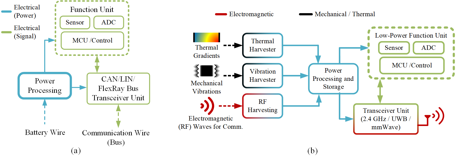
The conventional vehicular sensor node consists of three units: a power processing unit wired to the main battery, a wired vehicular network transceiver and a function unit which typically consists of microcontroller units (MCU), analog-to-digital converters (ADC) and sensing elements. The energy harvesting IVWSN node is different from the conventional node in two aspects as demonstrated in Fig. 1: it utilizes energy harvesting to power itself rather than receiving power from the main battery and it employs a wireless communication transceiver rather than a wired one. Due to these differences, IVWSN nodes have power and communication requirements that are different from conventional nodes.
II-B Node Requirements
There are five main functional domains in a vehicle: engine, powertrain, chassis, occupant safety and body. Power and communication requirements of conventional sensor nodes in these domains, which are distributed over the engine, chassis and passenger compartments on the vehicle, are shown in Table I. IVWSN node requirements are derived from these numbers with respect to two constraints: 1) power consumption due to limited harvested energy and 2) reliable and secure communication at a sufficient rate in the presence of noise and interference on the wireless channel.
II-B1 Low Power Consumption
To operate on the limited power harvested from available RF, thermal and vibration sources in the vehicular environment, an IVWSN node needs to be designed for very low power consumption; the feasible target is 10 mW [13]. There are three main approaches for lowering node power consumption: low-power sensor design, low-power transceiver design, and duty cycling.
Low-power sensor design considers hardware-specific methods such as sub-threshold or low-voltage operation [14] and smart soft methods such as lowering the sensing rate when the measured signal is changing slowly [15]. For transceivers, power consumption increases with higher rate and higher transmission power [16]. Therefore, low-power transceivers should employ the lowest possible rate and transmission power that satisfy communication requirements. Duty cycling can be employed for both sensors and transceivers; duty cycling refers to a node with a relaxed timing requirement switching itself into a low-consumption standby/sleep mode for the majority of its operational cycle [17].
Example IVWSN nodes from literature that utilize these three techniques have been demonstrated to consume 10 mW. A body inertial sensor that utilizes duty cycling and employs a low-power UWB transceiver has been shown to consume only 5 mW [18]. Similarly, a wireless occupant safety sensor (seat occupancy) has been shown to consume 2 mW on average [19]. On the other hand, there aren’t any current notable examples for engine, powertrain, chassis and occupant safety nodes with strict rate and timing requirements since they cannot effectively be duty cycled like the previous examples due to busy a operational cycle. However, those sensors can still benefit from special low-power sensor design and low-power transceiver design techniques to similarly lower their 100 mW power consumption to the target 10 mW level.
II-B2 Wireless Communication
IVWSN transceivers are required to provide sufficient rate, reliability and security in spite of noise and interference on the wireless communication channel. The levels of rate, reliability and security required are determined by the sensing rate and the safety-criticalness of the sensed data.
Rate requirements are derived from bit resolution and sensing rate requirements of nodes. The highest rate requirements are for powertrain and engine nodes since they are subject to the fastest dynamics on the vehicle. Typically, they measure physical quantities at 20 bit resolution and 10kHz sensing rates, resulting in a raw rate requirement of at most 200 kbps. Since the nodes also share the wireless communication medium, the actual rate requirements for the engine and powertrain domains are higher, on the order of 1 Mbps. Moreover, chassis and occupant safety sensors have lower rate requirements (i.e., up to 100 kbps) since they are subject to the slower vehicle and the passenger dynamics. Finally, body sensors have the lowest rate requirements (i.e., up to 10 kbps) since they typically require very low bit resolution or simply have binary detection tasks.
Security and reliability pertains to attaining a low packet loss ratio under noise and interference on the wireless communication channel. The security and reliability requirement for an IVWSN node is determined with respect to the severeness of packet loss for that node. Body sensors have a low security and reliability requirement since their tasks are not safety-critical (e.g., windshield fog detection, theft detection). On the other hand, safety-critical nodes in the engine, powertrain, chassis and occupant safety domains (e.g., knock, wheel speed, airbag) have a high security and reliability requirement since packet losses for those nodes can lead to fatal accidents.
III RF Communication for IVWSN
In this section, we evaluate the performance of 2.4 GHz, UWB and mmWave in terms of communication rate, reliability and security requirements of IVWSN nodes by considering path and penetration loss measurements for node locations in the chassis, engine and passenger compartments of a Fiat Linea MY 2009 together with models of state-of-the-art transceivers from literature. The transceiver models consider the maximum achievable reliable communication rate, maximum allowed transmit power, transceiver noise level and power consumption metrics.
III-A Rate
Rate performance for each technology is evaluated by comparing the maximum achievable rates of the transceivers with the rate requirements of IVWSN nodes for each domain (provided in Table I). While state-of-the-art transceivers for 2.4 GHz have been shown to provide 0.25-54 Mbps [20, 21, 22], mmWave [23, 24, 25] and UWB [26, 27] transceivers generally provide rates higher than 3000 Mbps, up to a maximum of 7000 Mbps. Therefore, all technologies have transceiver examples that are capable of at least an order of magnitude higher rates than the associated requirements in Table I. For our later analyses, we choose one of these examples for each technology as our transceiver model. Regarding the low power consumption requirement and the rate versus power consumption trade-off for transceivers [16], the transceiver that consumes the least power is chosen among options that satisfy the rate requirements. These are, [20] for 2.4 GHz, [23] for mmWave and [27] for UWB.
III-B Security and Reliability
Security and reliability performance analysis is based on the communication performance in the presence of noise and interference. For fair comparison, since the packet loss is determined by the SINR, we evaluate the worst-case SINR for each link, for each technology, in all compartments. The worst-case SINR for a link occurs with maximum interference power which considers the maximum interferer transmit (TX) power and the minimum penetration loss for that compartment and technology. While path and penetration loss are measured, maximum TX powers for both the interferer and the communicator, and the noise power are determined from transceiver specifications and associated standards.
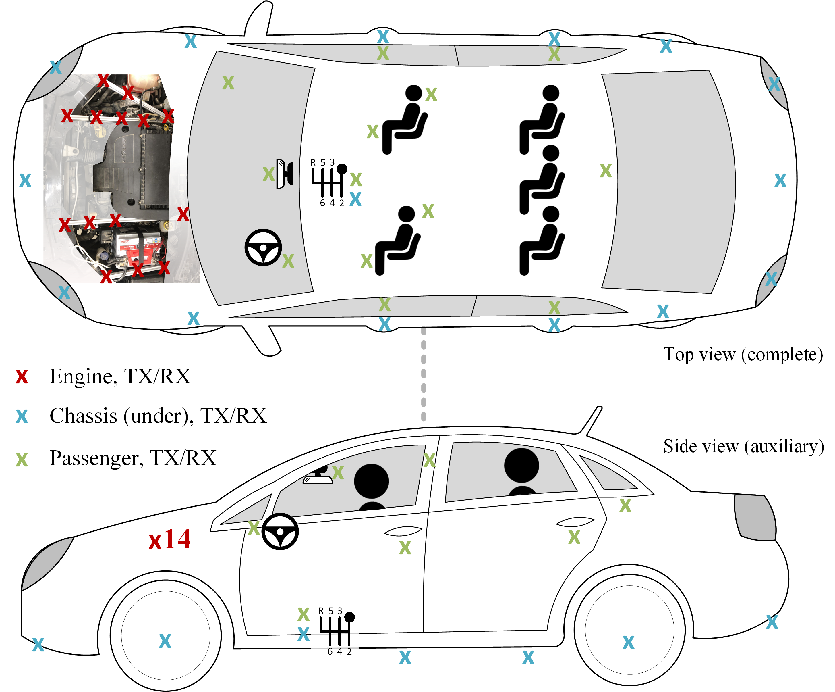
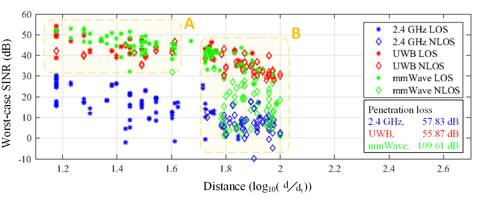
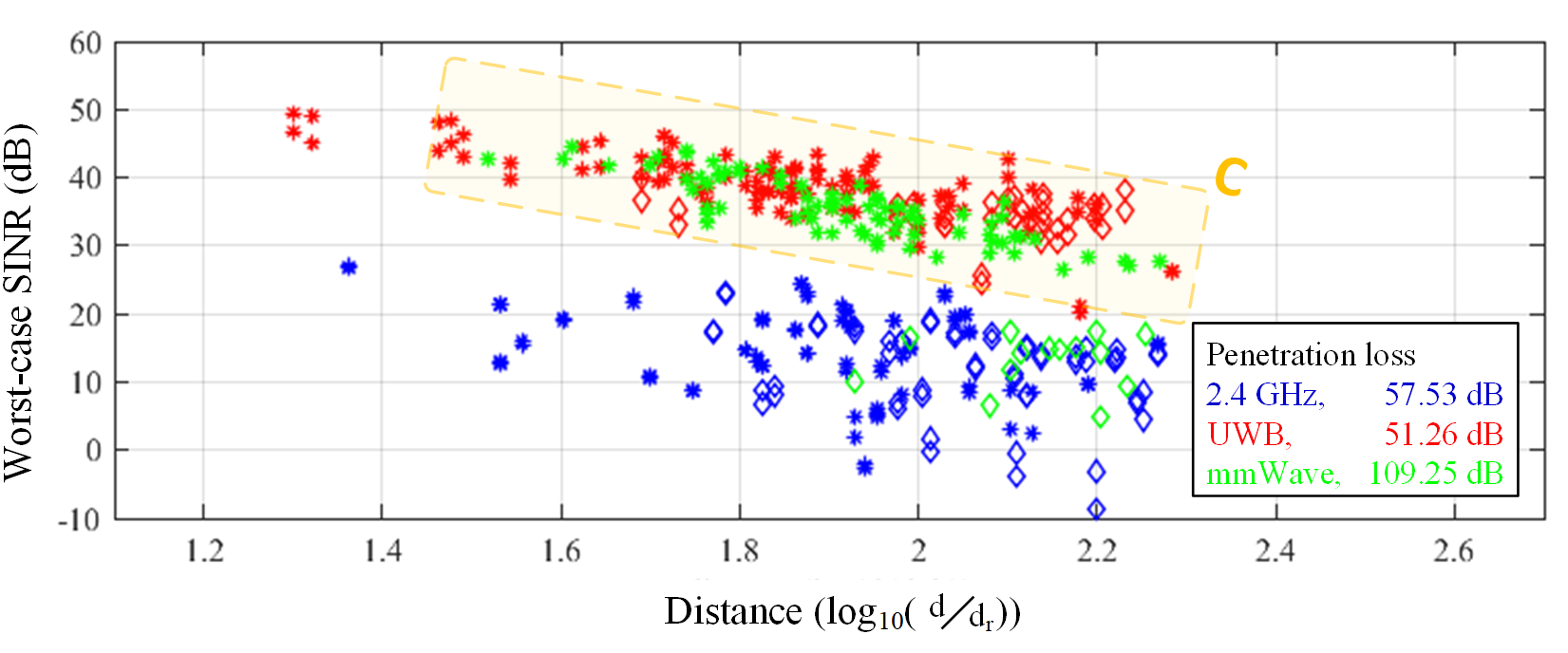
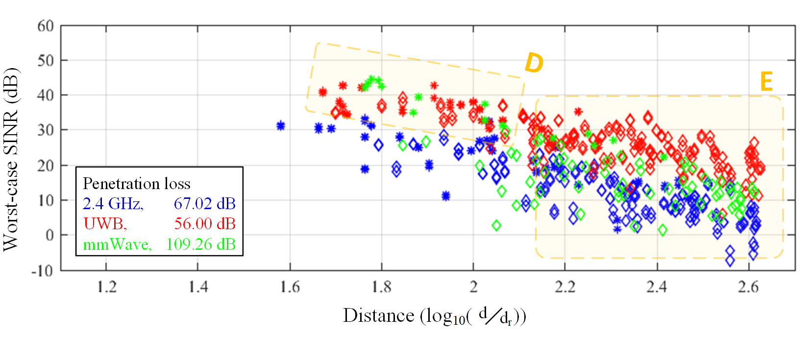
Penetration loss was measured by placing a receiver (RX) antenna in each compartment and recording received power levels for transmitter (TX) antenna locations on a 1m perimeter around the RX antenna. Path loss measurements were conducted for 182, 156 and 210 different links for the chassis, engine and passenger compartments, respectively (Fig. 2). Using the path and penetration loss measurements, the maximum transmit power levels (52, 60 and -11.3 dBm including 30, 50 and 0 dBi antenna gains for 2.4 GHz, mmWave and UWB, respectively [4, 28]) and the selected low-power transceiver noise levels (-76 dBm for 2.4 GHz [20], -68 dBm for mmWave [23] and -84 dBm for UWB [27]) we compute the worst-case SINR for each link, for each technology, in all compartments, as shown in Fig. 3, where the ”reference distance”, dr, is 1 cm. The minimum penetration loss values used in the worst-case SINR computations for each technology in each compartment are also provided in Fig. 3.
The results in Fig. 3 show that mmWave performs best for the short LoS links in the engine compartment (sector A) due to high directionality and low interference, but UWB surpasses mmWave for the non-LoS links due to lower attenuation (sector B). For LoS links in the passenger compartment (sector C) and the chassis (sector D), which are inherently longer distance, mmWave faces higher attenuation compared to UWB and thus the two perform similarly. However, majority of the links in the chassis are non-LoS; UWB therefore performs best in the chassis (sector E). Both UWB and 2.4 GHz receive high interference from external sources in all compartments due to low penetration losses. While 2.4 GHz suffers heavily from this, UWB utilizes narrowband interference suppression techniques at the cost of having a lower bandwidth, converging its SINR towards signal-to-noise ratio (SNR) (e.g., narrow-band interference suppression with adaptive notch filters [29]). mmWave inherently experiences very low inteference since mmWave interferers face very high penetration losses in all compartments.
III-C Feasible RF Communication for IVWSN
Overall, regarding the above results and the communication requirements of IVWSN nodes provided in Table I, the rate requirement for all nodes in all compartments can be satisfied by all technologies. Evaluations on the worst-case SINR levels for all links, for technologies, in all compartments show that mmWave provides the highest security and reliability for short LoS links in the engine compartment and is comparable to UWB for LoS links in the other compartments. For non-LoS links, UWB is the best performer in all compartments. While UWB and 2.4 GHz both experience high interference due to low penetration loss, by sacrificing some of its bandwidth UWB employs narrowband interference suppression techniques and preserves its high SINR; 2.4 GHz suffers heavily and therefore is not secure. mmWave inherently experiences very low interference due to very high penetration losses in its frequency band.
IV Energy Harvesting for IVWSN
In this section, we evaluate the potential for energy harvesting in the engine, chassis and passenger compartments. To this end, we apply recorded temperature and acceleration data from a Fiat Tipo 2016 during typical driving scenarios and path loss measurements from the previous section to harvester models from the literature. The energy harvester models consider both the harvester dynamics and power processing efficiencies to estimate their useful power outputs.

IV-A RF Sources
Radio frequency energy harvesting (RFEH) is used to convert part of the electromagnetic (EM) energy in received RF communication signals to useful power. Consisting of antennas, rectifiers, matching and switching circuits, the useful power output of an RFEH system depends on the received power and the component efficiencies. Reported efficiencies for state-of-the-art harvesters are 11.5% - 40% for [-10, 18]-dBm input power at a sensitivity of -20 dBm for 2.4 GHz [30, 31], 5% - 10% for [-36, -25]-dBm input power at a sensitivity of -36 dBm for UWB [32] and peak 12% with a sensitivity of 2 dBm for mmWave [33, 31].
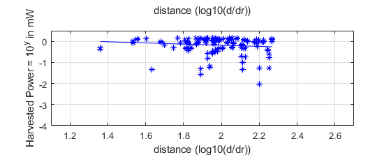
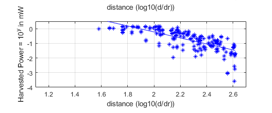
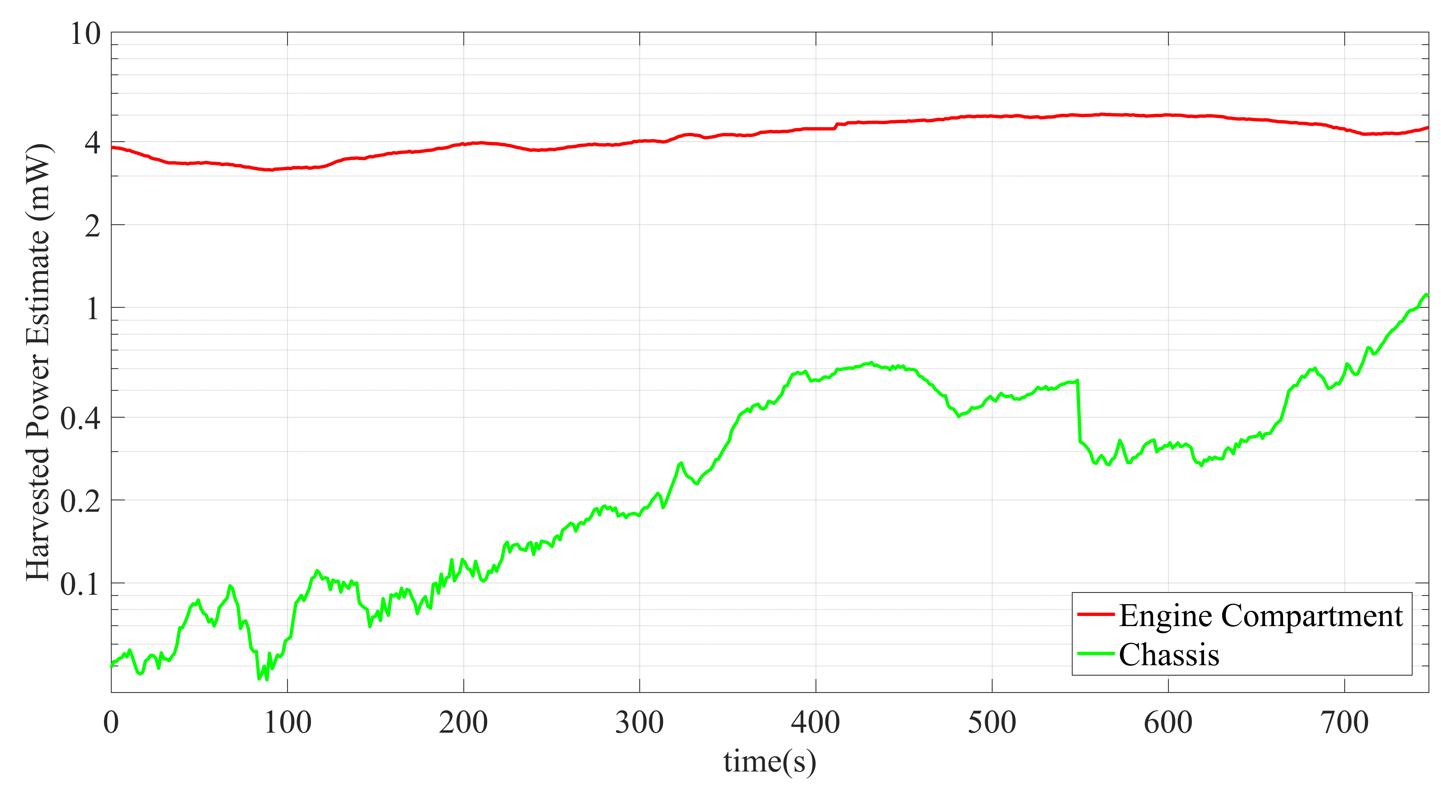
We estimate the actual harvestable power outputs in each compartment for each technology by applying the received power measurements from the previous section and the above mentioned efficiency levels from literature to our simulated RFEH model. The results demonstrate two feasible options as shown in Fig. 4: up to 1 mW can be harvested from 2.4 GHz in all compartments, and up to 0.1 mW can be harvested from mmWave in only the engine compartment.
IV-B Vibration Sources
Vibration energy harvester generates useful electrical power from the ambient vibrations. In an IVWSN framework, this task can best be achieved with magnet-coil type nonlinear electromagnetic harvesters (EMH) since they provide broad-band harvesting performance, and can thus accommodate for the typical varying frequency and high impact (1-10 g on parts weighing kilograms) vibrations in a vehicle. Other choices such as piezoelectric and electrostatic harvesters are not suitable due to their low durability and design for smaller vibrations [34].
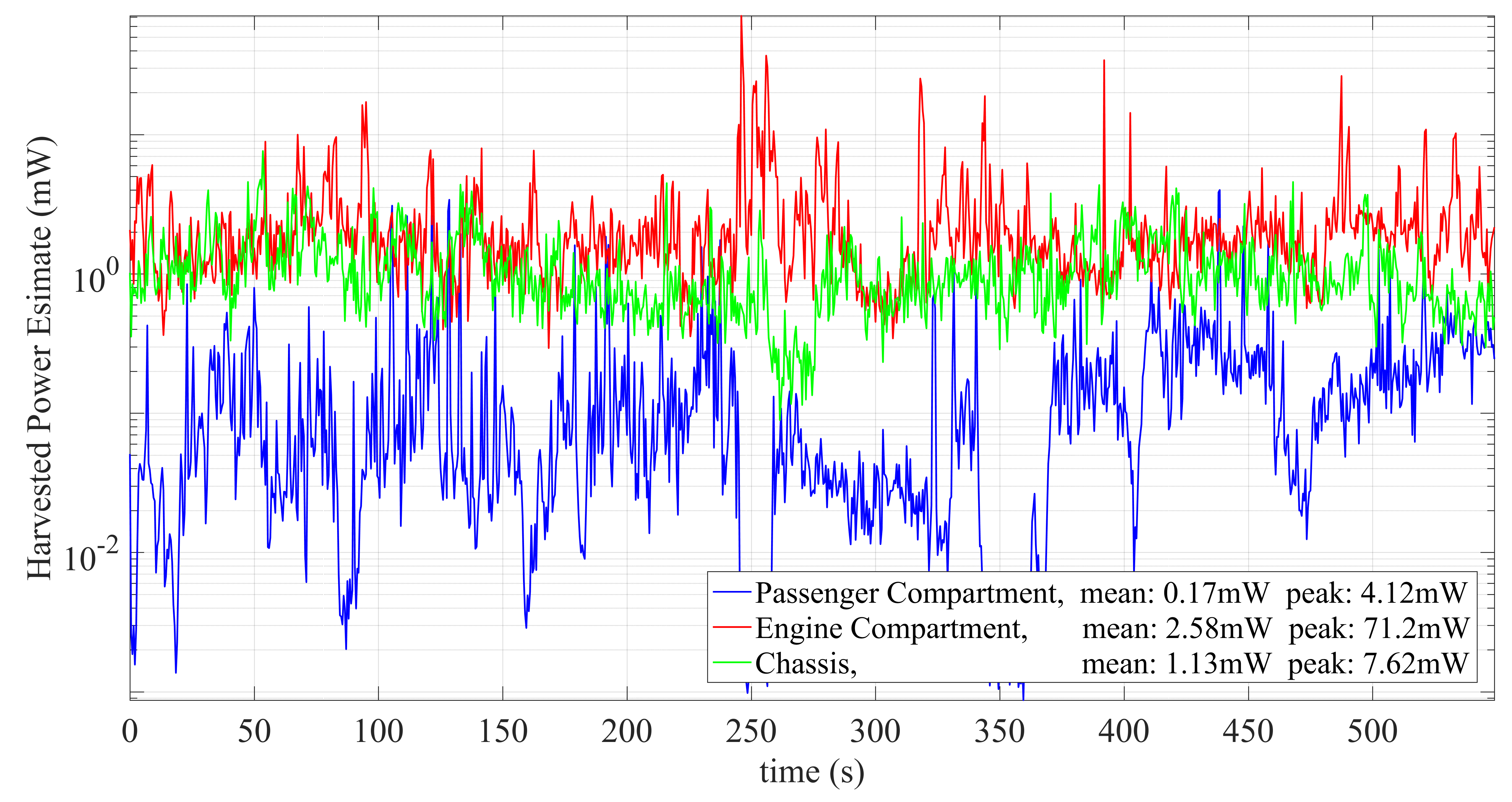
In order to estimate the potential power harvestable by such an EMH, we recorded acceleration data (with an ADXL345 accelerometer) during typical driving scenarios (with a Fiat Tipo 2016) from the engine block, the rear pillar inside the passenger compartment and the transmission unit under the chassis. We applied the measured acceleration data to a state-of-the-art EMH model [35] in simulation environment and estimated the raw power output. The model considers the transfer characteristics of the harvester, in which raw output power is proportional to the square of the input acceleration. However, the raw output of the EMH needs to be processed by additional power electronics to generate useful power; this typically adds a 50% efficiency factor to the power output [36, 37]. The useful electrical power output of the EMH is shown Fig. 5 (a): mean 170 \textmugreekW and 4.12 mW peak for the passenger compartment, mean 2.58 mW and peak 71.2 mW for the engine compartment and mean 1.13 mW peak 7.62 mW for the chassis.
IV-C Thermal Sources
Thermoelectric generators (TEG) convert the heat flow due to temperature difference between their two sides to DC electrical power. TEG power output can be estimated from temperature measurements of these two sides. We collected simultaneous hot surface and ambient temperature data with K-type thermocouples and a MAX31856 amplifier module from the hot exit of the coolant pipe from the engine block, the rear pillar inside the passenger compartment and the transmission unit under the chassis on the same vehicle, during the same driving conditions as the vibration case. We applied the measured temperature data to a TEG model [38] and estimated the raw power output. The model considers the transfer characteristics of the harvester, in which raw output power is proportional to the square of the temperature difference on its two sides. For generating useful power, the low voltage DC raw TEG output also needs additional power processing circuitry, which brings a 30% efficiency factor for the considered TEG model [38]. The passenger compartment measurements showed temperature differences around 2°C, which is below the minimum 10°C difference required for harvesting [38, 39]. Therefore, thermal energy harvesting inside the passenger compartment is not feasible. The useful electrical power output of the TEG is shown in Fig. 5 (b): 4 mW for the engine compartment (after the engine heats up) and on average 0.5 mW for the chassis.
IV-D Feasible Energy Harvesting for IVWSN
Overall, regarding the above results and the requirements for low-power IVWSN nodes in Section II, vibration, thermal and RF energy harvesters can generate enough power to supply all nodes consuming 10 mW in the engine compartment and all 5 mW nodes in the chassis. While RF and thermal sources provide stable outputs, vibration harvesters can occasionally peak at very high levels (e.g., engine, 71.2 mW) which can be stored for later use. In the passenger compartment, thermal sources cannot provide significant power due to low temperature gradients and vibration sources can support RF sources with 1 mW on average due to low amplitude vibrations.
V Conclusion
IVWSN s enable vehicular sensor nodes inside inaccessible locations such as tires and they free the vehicle of the wiring harness, significantly lowering cost and fuel consumption. We provide an empirical feasibility analysis of such an IVWSN framework by evaluating the potential of 2.4 GHz, UWB and mmWave communication and RF, vibration and thermal energy harvesting technologies for the chassis, engine and passenger compartments
Analysis of state-of-the-art transceivers for 2.4 GHz, UWB and mmWave show that rate requirements for all IVWSN nodes can be met by all technologies. Path and penetration loss measurements demonstrate that mmWave provides the highest SINR and thus the highest security and reliability for the short LoS links in the engine compartment. However, due to higher attenuation over longer link distances, mmWave is comparable to UWB for LoS links in the other two compartments. For non-LoS links in all compartments and especially in the chassis, UWB provides the highest SINR due to lower attenuation. 2.4 GHz is not secure since it suffers heavily from interference. While UWB is also vulnerable, it utilizes narrowband interference suppression techniques in exchange for lower bandwidth. mmWave inherently experiences very low interference due to very high penetration loss in all compartments.
For RF energy harvesting, 2.4 GHz is the best performer, providing 0.1-1 mW useful power for most links in all compartments; UWB cannot provide any useful power and mmWave can only provide up to 0.1 mW only in the engine compartment. Vibration and thermal harvesting can support RFEH to power all IVWSN nodes that have 10 mW consumption in the engine compartment and all nodes that have 5 mW consumption in the chassis. Thermal sources cannot provide significant power in the passenger compartment due to insufficient temperature gradients, and vibration sources can support RF sources with only 1 mW on average due to low vibration levels. While these analyses empirically confirm the feasibility of the IVWSN framework from power and communication perspectives in different vehicle compartments, as future work, we aim to conduct an experimental study with actual low-power IVWSN nodes with harvesters and low-power transceivers and sensors.
References
- [1] N. Navet, Y. Song, F. Simonot-Lion, and C. Wilwert, “Trends in automotive communication systems,” Proceedings of the IEEE, vol. 93, pp. 1204–1223, June 2005.
- [2] N. Navet and F. Simonot-Lion, “In-vehicle communication networks-a historical perspective and review,” tech. rep., University of Luxembourg, 2013.
- [3] S. C. Ergen, A. Sangiovanni-Vincentelli, X. Sun, R. Tebano, S. Alalusi, G. Audisio, and M. Sabatini, “The tire as an intelligent sensor,” IEEE Transactions on Computer-Aided Design of Integrated Circuits and Systems, vol. 28, pp. 941–955, July 2009.
- [4] S. Coleri Ergen and A. Sangiovanni-Vincentelli, “Intravehicular energy-harvesting wireless networks: Reducing costs and emissions,” IEEE Vehicular Technology Magazine, vol. 12, pp. 77–85, Dec 2017.
- [5] Y. Bai, H. Jantunen, and J. Juuti, “Energy harvesting research: The road from single source to multisource,” Advanced Materials, vol. 30, no. 34, p. 1707271, 2018.
- [6] O. K. Tonguz, H. Tsai, C. Saraydar, T. Talty, and A. Macdonald, “Intra-car wireless sensor networks using rfid: Opportunities and challenges,” in 2007 Mobile Networking for Vehicular Environments, pp. 43–48, May 2007.
- [7] H. Tsai, O. K. Tonguz, C. Saraydar, T. Talty, M. Ames, and A. Macdonald, “Zigbee-based intra-car wireless sensor networks: a case study,” IEEE Wireless Communications, vol. 14, pp. 67–77, December 2007.
- [8] U. Demir, C. U. Bas, and S. Coleri Ergen, “Engine compartment uwb channel model for intravehicular wireless sensor networks,” IEEE Transactions on Vehicular Technology, vol. 63, pp. 2497–2505, July 2014.
- [9] C. U. Bas and S. C. Ergen, “Ultra-wideband channel model for intra-vehicular wireless sensor networks beneath the chassis: From statistical model to simulations,” IEEE Transactions on Vehicular Technology, vol. 62, pp. 14–25, Jan 2013.
- [10] A. Chandra, A. Prokeš, T. Mikulášek, J. Blumenstein, P. Kukolev, T. Zemen, and C. F. Mecklenbräuker, “Frequency-domain in-vehicle uwb channel modeling,” IEEE Transactions on Vehicular Technology, vol. 65, pp. 3929–3940, June 2016.
- [11] J. Blumenstein, A. Prokes, A. Chandra, T. Mikulasek, R. Marsalek, T. Zemen, and C. Mecklenbräuker, “In-vehicle channel measurement, characterization, and spatial consistency comparison of 30–11 GHz and 55–65 GHz frequency bands,” IEEE Transactions on Vehicular Technology, vol. 66, pp. 3526–3537, May 2017.
- [12] M. Schack, M. Jacob, and T. Kiirner, “Comparison of in-car uwb and 60 ghz channel measurements,” in Proceedings of the Fourth European Conference on Antennas and Propagation, pp. 1–5, April 2010.
- [13] R. J. M. Vullers, R. v. Schaijk, H. J. Visser, J. Penders, and C. V. Hoof, “Energy harvesting for autonomous wireless sensor networks,” IEEE Solid-State Circuits Magazine, vol. 2, pp. 29–38, Spring 2010.
- [14] N. N. Tan, D. Li, and Z. Wang, Ultra-Low Power Integrated Circuit Design: Circuits, Systems, and Applications, vol. 85. Springer, 2013.
- [15] Freescale Semiconductor (NXP), “White paper: Low-power sensing, energy-efficient power solutions,” tech. rep., 2015.
- [16] B. W. Cook, A. Molnar, and K. S. J. Pister, “Low power rf design for sensor networks,” in 2005 IEEE Radio Frequency integrated Circuits (RFIC) Symposium - Digest of Papers, pp. 357–360, June 2005.
- [17] R. Min, M. Bhardwaj, Seong-Hwan Cho, E. Shih, A. Sinha, A. Wang, and A. Chandrakasan, “Low-power wireless sensor networks,” in VLSI Design 2001. Fourteenth International Conference on VLSI Design, pp. 205–210, Jan 2001.
- [18] P. Zhang, “Wsn prototype based on uwb radio,” Aug 2017. Dependable embedded wireless infrastructure (DEWI).
- [19] Monnit, Wireless Seat Occupancy Sensor, 2017.
- [20] Maxim, MAX2832 2.4GHz to 2.5GHz 802.11g RF Transceiver with Integrated PA, 2011. Rev. 2.
- [21] Texas Instruments (TI), CC2500 Low-Cost Low-Power 2.4 GHz RF Transceiver, May 2009. Rev. C.
- [22] Freescale Semiconductor, MC213 2.4 GHz Low Power Transceiver, 2009. Rev. 1.8.
- [23] V. Vidojkovic, G. Mangraviti, K. Khalaf, V. Szortyka, K. Vaesen, W. Van Thillo, B. Parvais, M. Libois, S. Thijs, J. R. Long, C. Soens, and P. Wambacq, “A low-power 57-to-66ghz transceiver in 40nm lp cmos with -17db evm at 7gb/s,” in 2012 IEEE International Solid-State Circuits Conference, pp. 268–270, Feb 2012.
- [24] S. Emami, R. F. Wiser, E. Ali, M. G. Forbes, M. Q. Gordon, X. Guan, S. Lo, P. T. McElwee, J. Parker, J. R. Tani, J. M. Gilbert, and C. H. Doan, “A 60ghz cmos phased-array transceiver pair for multi-gb/s wireless communications,” in 2011 IEEE International Solid-State Circuits Conference, pp. 164–166, Feb 2011.
- [25] K. Okada, K. Matsushita, K. Bunsen, R. Murakami, A. Musa, T. Sato, H. Asada, N. Takayama, N. Li, S. Ito, W. Chaivipas, R. Minami, and A. Matsuzawa, “A 60ghz 16qam/8psk/qpsk/bpsk direct-conversion transceiver for ieee 802.15.3c,” in 2011 IEEE International Solid-State Circuits Conference, pp. 160–162, Feb 2011.
- [26] decaWave, DW1000 single chip Ultra Wideband (UWB) low-power low-cost transceiver IC. Rev. 2.19.
- [27] M. U. Nair, Y. Zheng, C. W. Ang, Y. Lian, X. Yuan, and C. Heng, “A low sir impulse-uwb transceiver utilizing chirp fsk in 0.18 cmos,” IEEE Journal of Solid-State Circuits, vol. 45, pp. 2388–2403, Nov 2010.
- [28] “ecfr - code of federal regulations,” Jan 2020.
- [29] H. Arslan, Z. N. Chen, and M.-G. Di Benedetto, Ultra wideband wireless communication. John Wiley & Sons, 2006.
- [30] A. Sedeek, E. Tammam, and E. Hasaneen, “High efficiency 2.45 ghz low power hybrid junction rectifier for rf energy harvesting,” in 2018 International Japan-Africa Conference on Electronics, Communications and Computations (JAC-ECC), pp. 147–150, Dec 2018.
- [31] Y. Wu, J. P. M. G. Linnartz, H. Gao, P. G. M. Baltus, and J. W. M. Bergmans, “System study of a 60 ghz wireless-powered monolithic sensor system,” in 2011 8th International Conference on Information, Communications Signal Processing, pp. 1–5, Dec 2011.
- [32] J. Kang, P. Chiang, and A. Natarajan, “A 3.6cm2 wirelessly-powered uwb soc with -30.7dbm rectifier sensitivity and sub-10cm range resolution,” in 2015 IEEE Radio Frequency Integrated Circuits Symposium (RFIC), pp. 255–258, May 2015.
- [33] M. Nariman, F. Shirinfar, S. Pamarti, A. Rofougaran, and F. De Flaviis, “High-efficiency millimeter-wave energy-harvesting systems with milliwatt-level output power,” IEEE Transactions on Circuits and Systems II: Express Briefs, vol. 64, pp. 605–609, June 2017.
- [34] C. Wei and X. Jing, “A comprehensive review on vibration energy harvesting: Modelling and realization,” Renewable and Sustainable Energy Reviews, vol. 74, pp. 1 – 18, 2017.
- [35] E. Dallago, M. Marchesi, and G. Venchi, “Analytical model of a vibrating electromagnetic harvester considering nonlinear effects,” IEEE Transactions on Power Electronics, vol. 25, pp. 1989–1997, Aug 2010.
- [36] G. D. Szarka, S. G. Burrow, and B. H. Stark, “Ultralow power, fully autonomous boost rectifier for electromagnetic energy harvesters,” IEEE Transactions on Power Electronics, vol. 28, pp. 3353–3362, July 2013.
- [37] P. D. Mitcheson, T. C. Green, and E. M. Yeatman, “Power processing circuits for electromagnetic, electrostatic and piezoelectric inertial energy scavengers,” Microsystem Technologies, vol. 13, no. 11-12, pp. 1629–1635, 2007.
- [38] W. Wang, V. Cionca, N. Wang, M. Hayes, B. O’Flynn, and C. O’Mathuna, “Thermoelectric energy harvesting for building energy management wireless sensor networks,” International Journal of Distributed Sensor Networks, vol. 9, no. 6, p. 232438, 2013.
- [39] D. Enescu, “Thermoelectric energy harvesting: Basic principles and applications,” in Green Energy Advances, IntechOpen, 2019.