Study of Cloud-Aided Multi-Way Multiple-Antenna Relaying with Best-User Link Selection and Joint ML Detection
Abstract
In this work, we present a cloud-aided uplink framework for multi-way multiple-antenna relay systems which facilitates joint linear Maximum Likelihood (ML) symbol detection in the cloud and where users are selected to simultaneously transmit to each other aided by relays. We also investigate relay selection techniques for the proposed cloud-aided uplink framework that uses cloud-based buffers and physical-layer network coding. In particular, we develop a novel multi-way relay selection protocol based on the selection of the best link, denoted as Multi-Way Cloud-Aided Best-User-Link (MWC-Best-User-Link). We then devise the maximum minimum distance relay selection criterion along with the algorithm that is incorporated into the proposed MWC-Best-User-Link protocol. Simulations show that MWC-Best-User-Link outperforms previous works in terms of average delay, sum-rate and bit error rate.
Index Terms:
Multi-Way Relay Channel, Cooperative diversity, Maximum Likelihood detection, MIMOI INTRODUCTION
In wireless networks, the use of cooperative diversity [1] can mitigate the signal fading caused by multipath propagation. The Multi-Way Relay Channel (mRC) [2] includes both a full data exchange model, in which each user receives data from all other users, and the pairwise data exchange model, which is composed by multiple two-way relay channels. The incorporation of mRC with multiple relays in a system can significantly improve its performance. Considering 5G requirements [3], high spectrum efficiency relaying strategies are key due to their excellent performance. The use of a cloud as a central node can leverage the performance of relay techniques as network operations and services have recently adopted cloud-enabled solutions in communication networks [4]. The ability to cost-effectively manage interference is one of the main advantages of adopting the cloud network framework [4]. In the Cloud Radio Access Network (C-RAN) architecture, the baseband processing, usually performed locally at each base-station (BS), is aggregated and performed centrally at a cloud processor. This is enabled by high-speed connections, denoted as fronthaul links, between the BSs and the cloud [4]. This centralized signal processing enables the interference mitigation across all the users in the uplink and downlink. The BSs in the C-RAN are also referred to remote radio heads (RRHs) as their functionality is often limited to transmission and reception of radio signals [4].
The mRC has multiple clusters of users in which each user aims to multicast a single message to all the other users in the same cluster [2]. Processing users in a cluster corresponds to an -way information exchange among the users in the same cluster. A group of relays facilitates this exchange, by helping all the users in the system. In particular, the mRC pairwise data exchange model () is formed by multiple two-way relay channels. In Two-Way Multiple-Access Broadcast Channel (MABC) schemes, based on the decode-and-forward (DF) protocol [5], the transmission is organized in two successive phases: 1) MA phase - a relay is selected for receiving and decoding the messages simultaneously transmitted from two users (sources and ) and physical-layer network coding (PLNC) is performed on the decoded messages; 2) BC phase - the same selected relay broadcasts the decoded messages to the two sources. The Two-Way Max-Min (TW-Max-Min) relay selection protocol [5] has a high performance, when all the channels are reciprocal and fixed during two consecutive time slots (MA and BC phases). Otherwise, with non reciprocal channels, the performance of relaying strategies can be enhanced by adopting buffer-aided protocols, in which the relays are able to accumulate data in their buffers [6, 8], before sending data to the destination, as in the Multi-Way Max-Link (MW-Max-Link) [9] protocol for cooperative multi-input multi-output (MIMO) systems, which selects the best links among pairs of sources (diversity gain equals ), using the extended Maximum Minimum Distance (MMD) relay selection criterion [10, 11]. Furthermore, in [12], the Two-Way Max-Link (TW-Max-Link) protocol (a special case of MW-Max-Link, for a single two-way relay channel ()), also using the extended MMD criterion, was presented. However, cloud-aided multi-way protocols using the maximum minimum distance relay selection criterion, for multiple-antenna systems, in which each cluster has a particular buffer, have not been previously investigated.
In this work, we develop a cloud-aided framework and a Multi-Way Best-User-Link (MWC-Best-User-Link) protocol for cooperative MIMO systems, with non reciprocal channels, which selects the best links among pairs of sources (clusters) and relay nodes. In order to perform signal detection at the cloud and the nodes, we present maximum likelihood (ML) detectors. We then consider the maximum minimum distance criterion and devise a relay selection algorithm for MWC-Best-User-Link. Simulations illustrate the excellent performance of the proposed framework, the proposed MWC-Best-User-Link protocol and the relay selection algorithm as compared to previously reported approaches.
This paper is structured as follows. Section II describes the system model and the main assumptions. Section III presents the proposed MWC-Best-User-Link protocol, the relay selection criterion and algorithm, and analyzes MWC-Best-User-Link, in terms of pairwise error probability (PEP) and sum-rate. Section IV illustrates and discusses the simulation results whereas Section V gives the concluding remarks.
II System Description
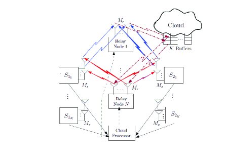
We assume a MIMO multi-way MABC relay network formed by clusters (pair of sources and ) and half duplex (HD) DF relays, ,…,. In a C-RAN framework, the sources would represent mobile users and the relays would represent RRHs. The sources have antennas for transmission or reception and each relay antennas, where , all of them used for reception () and a part of them used for transmission (), where , forming a spatial multiplexing network, in which the channel matrices are square or formed by multiple square sub-matrices in the MA mode. Note that the reason for using multiples of antennas at the relays is because the relay selection algorithms explained in Section III use criteria that depend on these matrices to be square or to be formed by multiple square sub-matrices. Moreover, the computational complexity The selected relays access a number of cloud buffers for extracting or storing packets in each time slot. Each cluster has a particular cloud buffer that is established on demand, whose size is packets, as depicted in Fig.1. In the multiple-access phase (uplink), a cluster is selected to send packets simultaneously to a selected relay for reception. Then, the data are decoded by the cloud processor, PLNC is employed on the decoded information and the resulting data are stored in their particular cloud buffers. In the broadcast-channel phase (downlink), two relays and are selected to broadcast packets from the particular cloud buffer to the selected cluster. Note that may be different from . In most of the situations the selection of only one relay in downlink is enough for a good performance [9, 10, 11, 12, 13]. However, by selecting two relays, the possibility of combining the channels related to the selected relays increases the degrees of freedom of the system and, consequently, its performance is improved. The system could select more than two relays to further improve its performance, but the computational complexity would be considerably increased for a high number of relays. For the sake of simplicity, we adopt the mRC pairwise data exchange model, but the full data exchange model can be considered in future works.
II-A Assumptions
The energy transmitted from each source node to the selected relay for reception () or from the selected relay(s) for transmission to the sources (), in each time slot, is the same, i. e., . We consider mutually independent zero mean complex Gaussian random channel coefficients, which are fixed for the duration of one time slot and vary independently from one time slot to the following, and the transmission is organized in data packets. The order of the packets is included in the preamble and the original order is recovered at the destination. Signaling for network coordination and pilot symbols for estimation of the channel state information (CSI) are also contained in the preamble. The cloud is the central node and decides whether a cluster or the relay(s) must transmit in a given time slot , through a feedback channel. An appropriate signalling provides global CSI at the cloud. Moreover, we assume that each relay only has information about its and links. The use of a cloud as a single central node and its buffers reduces the system complexity and the delay, since a unique central node decides which nodes transmit (rather than all destination nodes) and the packets associated with a cluster are stored in only its particular cloud buffer instead of being spread in the buffers of all relays. In this work, we focus on the ideal case where the fronthaul links have unconstrained capacities, and the relays can convey their exact received signals to the cloud processor. Practical systems, however, have capacity-constrained fronthaul links [4] and this limits the amount of information that the relays can retransmit. Although these unconstrained capacities in the fronthaul links simplify our analysis, it does not limit the advantages of the proposed protocol and relay selection algorithm, explained in the next section. Moreover, capacity-constrained fronthaul links can be considered elsewhere in future works and the performance achieved by the proposed protocol may be considered as a baseline or an upper bound.
II-B System Model
For multi-way HD DF MABC systems, in the MA phase, the signal sent by the selected cluster ( and ) and received at (the relay selected for reception) is organized in an vector given by
| (1) |
where is an vector with symbols sent by () and (), is a matrix of and links and is the zero mean additive white complex Gaussian noise (AWGN) at . Note that is formed by square sub-matrices of dimensions as given by
| (2) |
The Maximum Likelihood (ML) detector is the optimal detector from the point of view of minimizing the probability of error (assuming equiprobable ). However, the ML detector has high (exponential in ) complexity and is only suited to MIMO systems with a small number of antenna elements. Assuming perfect synchronization, we may adopt the ML receiver at the cloud processor:
| (3) |
where is each of the possible vectors of sent symbols ( is the quantity of symbols in the constellation adopted). The ML receiver calculates an estimate of the vector of symbols sent by the sources . Other suboptimal detection techniques could be considered in future work [17, 18, 19, 20, 21, 22, 54, 24, 25, 26, 27, 28, 31, 32, 33].
By performing PLNC, only the XOR outputs (resulting packets) are stored with the information: ”the bit sent by is equal (or not) to the corresponding bit sent by ”. Therefore, we apply the bitwise XOR:
| (4) |
and store the resulting data in the cloud buffer. Therefore, an advantage of applying PLNC is that we have to store only packets in the cloud buffer, instead of .
In the BC phase, the signal sent by the relays selected for transmission ( and ) and received at and is structured in an vector given by
| (5) |
where is a vector with symbols, represents the matrix of and links, and is the AWGN at or . Note that is formed by summing matrices of dimension as given by
| (6) |
We may also adopt the ML receiver at the selected cluster, which yields
| (7) |
where is each of the possible vectors with symbols.
Therefore, at we calculate the vector of symbols sent by by performing PLNC:
| (8) |
It is also applied at to calculate the vector of symbols sent by :
| (9) |
The estimated channel matrix is considered instead of in (3) and (7), when performing the ML receiver, by assuming imperfect CSI. Note that is computed as =+, where the variance of the mutually independent zero mean complex Gaussian coefficients is given by ( and ) [14], in which , in the MA phase, and , in the BC phase. Channel and parameter estimation [42, 43, 44, 45, 46, 47, 49, 50, 51, 52, 53, 54, 55] techniques could be considered in future work in order to develop algorithms for this particular setting.
III Proposed MWC-Best-User-Link Protocol and Relay Selection Algorithm
The system of Fig. 1 is equiped with the novel MWC-Best-User-Link protocol, which in each time slot may operate in two possible modes: MA or BC. The relay selection algorithm of the proposed MWC-Best-User-Link protocol may operate using the extended MMD [10] criterion. The MMD-based relay selection algorithm minimizes the error in the ML receiver and can be used for MIMO systems with a small number of antenna elements due to its reduced complexity in this case.
The MMD-based relay selection algorithm, in the MA mode, chooses the relay and the associated channel matrix with the largest minimum distance as given by
| (10) |
where , , and represent each possible vector formed by symbols and . The metric is calculated for each of the (combination of in ) possibilities, for each sub-matrix , and is the smallest of these values. Thus the selected matrix has the largest value. Moreover, the MMD-based relay selection algorithm, in the BC mode, chooses the relay and the associated channel matrix with the largest minimum distance as given by
| (11) |
where , and represent each possible vector formed by symbols and . The metric is calculated for each of the possibilities, for each matrix , and is the smallest of these values. Thus, the selected matrix has the largest value. The following subsections explain how this protocol works.
III-A Relay selection metric for MA and BC modes
For each cluster (formed by and ), in the first step, we calculate the metric
related to the links of each square sub-matrix associated with the relay , in the MA mode:
| (12) |
where and . In the second step, we compute the ordering on and find the smallest metric, for being critical:
| (13) |
In the third step, we compute the ordering on and find the largest metric:
| (14) |
where . After finding for each cluster , we compute the ordering and find the largest metric:
| (15) |
Therefore, we choose the cluster and the relay that fulfil (15) to receive packets from the selected cluster. For each cluster, in the fourth step, we calculate the metrics
related to the links of each matrix associated with each pair of relays and , for BC mode:
| (16) |
where , and . In the fifth step, this reasoning is also applied to calculate the metric . In the sixth step, we compare the metrics and and store the smallest one:
| (17) |
In the seventh step, after finding for each pair of relays, we compute the ordering and find the largest metric:
| (18) |
where . After finding for each cluster , we compute the ordering and find the largest metric:
| (19) |
Therefore, we select the cluster and the relays and that fulfil (19) to send simultaneously packets stored in the particular cloud buffer to the selected cluster. The estimated channel matrix is considered in (12) and (16), instead of , if we consider imperfect CSI. Alternatively, a designer can consider precoding techniques [34, 35, 36, 37, 38, 39, 40, 41, 47, 48] to help mitigate interference rather than open loop transmission.
III-B Choice of the transmission mode
After calculating the metrics related to the SR and RS
links and finding and , these metrics are compared and we select the transmission mode:
where , is the total number of packets stored in the cloud buffers, is a parameter that when reduced increases the probability of the protocol to operate in BC mode and, consequently, achieve a reduced average delay (low latency).
III-C Pairwise Error Probability
The PEP assumes an error event when is sent and the detector calculates an incorrect (where ), based on the received symbol [9, 10, 11]. Considering , in MA mode, and , in BC mode, the worst value of the PEP (PEP worst case) that occurs for the smallest value of () is given by
| (20) |
where , in the MA mode, and , in the BC mode. By considering that the probability of having no error in the two phases of the system is approximately given by the square of , an expression for calculating the worst case of the PEP for cooperative transmissions (CT), in each time slot is given by
| (21) |
Note that this expression may be used for calculating the worst case of the PEP, for both symmetric and asymmetric channels. The proposed MWC-Best-User-Link, using the MMD relay selection criterion, selects the channel matrix , minimizing the PEP worst case, as shown by
| (22) |
Consequently, the MMD relay selection criterion, by maximizing the minimum Euclidian distance between different vectors of transmitted symbols, minimizes the error in the ML receiver. This reasoning may be applied also for each of the square sub-matrices in a non square matrix (formed by multiple square sub-matrices). In a future journal version of this paper we develop a proof that shows that the MMD relay selection criterion minimizes the PEP worst case and, consequently, the error in the proposed MWC-Best-User-Link protocol, with ML receiver.
III-D Sum-Rate
In [9], a framework is proposed to analyze the sum-rate of the MW-Max-Link. In the following, we use this framework to compute the sum-rate of the proposed MWC-Best-User-Link. In the case of a time slot selected for MA mode, the sum-rate is given by
| (23) |
where . Furthermore, in the case of a time slot selected for BC mode, the sum-rate is given by
| (24) |
where . So, the average sum-rate () of the MWC-Best-User-Link scheme can be approximated by
| (25) |
where and are the number of time slots selected for SR and RS transmissions, respectively.
IV Simulation Results
We assess via simulations the proposed MWC-Best-User-Link and the existing MW-Max-Link [9], using the MMD-based relay selection algorithm, with the ML receiver. We employ BPSK signals and note that other constellations as QPSK and 16-QAM were not included but can be examined elsewhere. The average delay is calculated by considering the time a packet needs to reach the destination once it has left the source (no delay is measured when the packet resides at the source [15]). So, the delay is the number of time slots the packet stays in the cloud buffer. The performance of MWC-Best-User-Link and MW-Max-Link protocols was assessed for a set of values. Then, we found that sets of packets is sufficient to ensure a good performance. We consider perfect and imperfect CSI and symmetric unit power channels ( ). The signal-to-noise ratio (SNR) given by ranges from 0 to 10 dB, where is the energy transmitted from each source or the relay(s) and we consider . The transmission protocols were simulated for packets, each with symbols. We assumed perfect signaling between the cloud and the network, but imperfect signaling can be considered in future works.
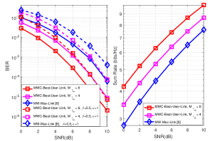
Fig. 2 depicts the BER and sum-rate performances of the MWC-Best-User-Link (MMD) and MW-Max-Link (MMD) protocols, for , , in MW-Max-Link and and in MWC-Best-User-Link, , , BPSK, , perfect and imperfect CSI ( and ). For both perfect and imperfect CSI (full and dashed curves, respectively), the BER performance of MWC-Best-User-Link is considerably better than that of MW-Max-Link for all the range of SNR values simulated. Note that the BER performance of MWC-Best-User-Link, with , obtains a gain of almost 3dB in SNR for the same BER as compared to that of MW-Max-Link. Moreover, the sum-rate performances of MWC-Best-User-Link are also considerably better than that of MW-Max-Link.
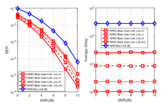
Fig. 3 illustrates the BER and the average delay performances of MWC-Best-User-Link (MMD) and MW-Max-Link (MMD), for BPSK, , , in MW-Max-Link, and in MWC-Best-User-Link, , , , 1, 5 and and perfect CSI. The average delay performance of MWC-Best-User-Link is considerably better than that of MW-Max-Link, as MWC-Best-User-Link has a unique set of cloud buffers. When we reduce the value of to 0 in the MWC-Best-User-Link protocol, the average delay is reduced to time slot, still keeping a considerably better BER performance than that of MW-Max-Link.
V Conclusions
A novel framework configured by a cloud as a central node with buffers has been introduced and investigated as a favorable relay selection strategy for multi-way protocols. We have examined relay-selection techniques for multi-way cooperative MIMO systems that are aided by a cloud central node, where a cluster with two sources is selected to simultaneously transmit to each other aided by relays. Simulations illustrate the excellent performance of the proposed MWC-Best-User-Link protocol, that by using the MMD-based relay selection algorithm, outperformed the existing MW-Max-Link scheme in terms of BER, sum-rate and average delay. In particular, this novel protocol has a considerably reduced average delay, keeping the high diversity gain.
References
- [1] J. N. Laneman; D. N. C. Tse; G. W. Wornell, ”Cooperative Diversity in Wireless Networks: Efficient Protocols and Outage Behavior”, in IEEE Trans. Inf. Theory., vol. 50, no. 12, pp. 3062-3080, Dec. 2004.
- [2] D. Gunduz; A.Yener; A. Goldsmith; H. Poor, ”The Multiway Relay Channel”, in IEEE Trans. Inf. Theory., vol. 59, no. 1, January 2013.
- [3] Z. Zhang, Z. Ma, M. Xiao, G. K. Karagiannidis, Z. Ding and P. Fan, ”Two-Timeslot Two-Way Full-Duplex Relaying for 5G Wireless Communication Networks,” in IEEE Transactions on Communications, vol. 64, no. 7, pp. 2873-2887, July 2016.
- [4] T. Q. S. Quek, M. Peng, O. Simeone, and W. Yu, Eds., ”Cloud Radio Access Networks: Principles, Technologies, and Applications”. Cambridge Univ. Press, February 2017.
- [5] I. Krikidis, ”Relay Selection for Two-Way Relay Channels With MABC DF: A Diversity Perspective,” in IEEE Transactions on Vehicular Technology, vol. 59, no. 9, pp. 4620-4628, Nov. 2010.
- [6] I. Krikidis, T. Charalambous, and J. Thompson, “Buffer-Aided Relay Selection for Cooperative Diversity Systems Without Delay Constraints,” IEEE Transactions on Wireless Communications, vol. 11, no. 5, pp. 1957–1967, May 2012.
- [7] T. Peng, R. C. de Lamare and A. Schmeink, ”Adaptive Distributed Space-Time Coding Based on Adjustable Code Matrices for Cooperative MIMO Relaying Systems,” IEEE Transactions on Communications, vol. 61, no. 7, pp. 2692-2703, July 2013.
- [8] J. Gu, R. C. de Lamare and M. Huemer, ”Buffer-Aided Physical-Layer Network Coding With Optimal Linear Code Designs for Cooperative Networks,” in IEEE Transactions on Communications, vol. 66, no. 6, pp. 2560-2575, June 2018.
- [9] F. L. Duarte and R. C. de Lamare, ”Buffer-Aided Max-Link Relay Selection for Multi-Way Cooperative Multi-Antenna Systems,” in IEEE Communications Letters, vol. 23, no. 8, pp. 1423-1426, Aug. 2019.
- [10] F. L. Duarte and R. C. de Lamare, ”Switched Max-Link Buffer-Aided Relay Selection for Cooperative Multiple-Antenna Systems,” SCC 2019; 12th International ITG Conference on Systems, Communications and Coding, Rostock, Germany, 2019, pp. 1-6.
- [11] F. L. Duarte and R. C. de Lamare, ”Switched Max-Link Relay Selection Based on Maximum Minimum Distance for Cooperative MIMO Systems,” IEEE Transactions on Vehicular Technology, 2019.
- [12] F. L. Duarte and R. C. de Lamare, ”Buffer-Aided Max-Link Relay Selection for Two-Way Cooperative Multi-Antenna Systems”, in 2019 16th International Symposium on Wireless Communication Systems (ISWCS), Oulu, Finland, 2019, pp. 288-292.
- [13] P. Clarke and R. C. de Lamare, ”Transmit Diversity and Relay Selection Algorithms for Multirelay Cooperative MIMO Systems,” in IEEE Transactions on Vehicular Technology, vol. 61, no. 3, pp. 1084-1098, March 2012.
- [14] H. Joudeh and B. Clerckx, ”Sum-Rate Maximization for Linearly Precoded Downlink Multiuser MISO Systems With Partial CSIT: A Rate-Splitting Approach,” in IEEE Transactions on Communications, vol. 64, no. 11, pp. 4847-4861, Nov. 2016.
- [15] D. Poulimeneas, T. Charalambous, N. Nomikos, I. Krikidis, D. Vouyioukas and M. Johansson, ”Delay- and diversity-aware buffer-aided relay selection policies in cooperative networks,” 2016 IEEE Wireless Communications and Networking Conference, Doha, 2016, pp. 1-6.
- [16] F. L. Duarte and R. C. de Lamare, “Switched Max-Link Relay Selection Based on Maximum Minimum Distance for Cooperative MIMO Systems”, IEEE Transactions on Vehicular Technology, 2020.
- [17] R. C. de Lamare, ”Massive MIMO systems: Signal processing challenges and future trends,” in URSI Radio Science Bulletin, vol. 2013, no. 347, pp. 8-20, Dec. 2013.
- [18] W. Zhang et al., ”Large-Scale Antenna Systems With UL/DL Hardware Mismatch: Achievable Rates Analysis and Calibration,” in IEEE Transactions on Communications, vol. 63, no. 4, pp. 1216-1229, April 2015.
- [19] R. C. de Lamare and R. Sampaio-Neto, ”Adaptive MBER decision feedback multiuser receivers in frequency selective fading channels,” in IEEE Communications Letters, vol. 7, no. 2, pp. 73-75, Feb. 2003.
- [20] R. C. De Lamare, R. Sampaio-Neto and A. Hjorungnes, ”Joint iterative interference cancellation and parameter estimation for cdma systems,” in IEEE Communications Letters, vol. 11, no. 12, pp. 916-918, December 2007.
- [21] R. C. De Lamare and R. Sampaio-Neto, “Minimum Mean-Squared Error Iterative Successive Parallel Arbitrated Decision Feedback Detectors for DS-CDMA Systems,” in IEEE Transactions on Communications, vol. 56, no. 5, pp. 778-789, May 2008.
- [22] Y. Cai and R. C. de Lamare, ”Space-Time Adaptive MMSE Multiuser Decision Feedback Detectors With Multiple-Feedback Interference Cancellation for CDMA Systems,” in IEEE Transactions on Vehicular Technology, vol. 58, no. 8, pp. 4129-4140, Oct. 2009.
- [23] R. C. de Lamare and R. Sampaio-Neto, ”Adaptive Reduced-Rank Equalization Algorithms Based on Alternating Optimization Design Techniques for MIMO Systems,” in IEEE Transactions on Vehicular Technology, vol. 60, no. 6, pp. 2482-2494, July 2011.
- [24] P. Li, R. C. de Lamare and R. Fa, “Multiple Feedback Successive Interference Cancellation Detection for Multiuser MIMO Systems,” in IEEE Trans. on Wireless Comm., vol. 10, no. 8, pp. 2434-2439, Aug. 2011.
- [25] P. Li and R. C. De Lamare, ”Adaptive Decision-Feedback Detection With Constellation Constraints for MIMO Systems,” in IEEE Transactions on Vehicular Technology, vol. 61, no. 2, pp. 853-859, Feb. 2012.
- [26] R. C. de Lamare, “Adaptive and Iterative Multi-Branch MMSE Decision Feedback Detection Algorithms for Multi-Antenna Systems,” in IEEE Transactions on Wireless Communications, vol. 12, no. 10, pp. 5294-5308, October 2013.
- [27] P. Li and R. C. de Lamare, ”Distributed Iterative Detection With Reduced Message Passing for Networked MIMO Cellular Systems,” in IEEE Transactions on Vehicular Technology, vol. 63, no. 6, pp. 2947-2954, July 2014.
- [28] Y. Cai, R. C. de Lamare, B. Champagne, B. Qin and M. Zhao, ”Adaptive Reduced-Rank Receive Processing Based on Minimum Symbol-Error-Rate Criterion for Large-Scale Multiple-Antenna Systems,” in IEEE Transactions on Communications, vol. 63, no. 11, pp. 4185-4201, Nov. 2015.
- [29] H. Ruan and R. C. de Lamare, ”Robust Adaptive Beamforming Using a Low-Complexity Shrinkage-Based Mismatch Estimation Algorithm,” IEEE Signal Processing Letters, vol. 21, no. 1, pp. 60-64, Jan. 2014.
- [30] H. Ruan and R. C. de Lamare, ”Robust Adaptive Beamforming Based on Low-Rank and Cross-Correlation Techniques,” IEEE Transactions on Signal Processing, vol. 64, no. 15, pp. 3919-3932, 1 Aug.1, 2016.
- [31] A. G. D. Uchoa, C. T. Healy and R. C. de Lamare, ”Iterative Detection and Decoding Algorithms for MIMO Systems in Block-Fading Channels Using LDPC Codes,” in IEEE Transactions on Vehicular Technology, vol. 65, no. 4, pp. 2735-2741, April 2016.
- [32] Z. Shao, R. C. de Lamare and L. T. N. Landau, ”Iterative Detection and Decoding for Large-Scale Multiple-Antenna Systems With 1-Bit ADCs,” in IEEE Wireless Communications Letters, vol. 7, no. 3, pp. 476-479, June 2018.
- [33] R. B. Di Renna and R. C. de Lamare, ”Adaptive Activity-Aware Iterative Detection for Massive Machine-Type Communications,” in IEEE Wireless Communications Letters, vol. 8, no. 6, pp. 1631-1634, Dec. 2019.
- [34] K. Zu and R. C. de Lamare, ”Low-Complexity Lattice Reduction-Aided Regularized Block Diagonalization for MU-MIMO Systems,” in IEEE Communications Letters, vol. 16, no. 6, pp. 925-928, June 2012.
- [35] Y. Cai, R. C. de Lamare, and R. Fa, “Switched Interleaving Techniques with Limited Feedback for Interference Mitigation in DS-CDMA Systems,” IEEE Transactions on Communications, vol.59, no.7, pp.1946-1956, July 2011.
- [36] Y. Cai, R. C. de Lamare, D. Le Ruyet, “Transmit Processing Techniques Based on Switched Interleaving and Limited Feedback for Interference Mitigation in Multiantenna MC-CDMA Systems,” IEEE Transactions on Vehicular Technology, vol.60, no.4, pp.1559-1570, May 2011.
- [37] K. Zu, R. C. de Lamare and M. Haardt, ”Generalized Design of Low-Complexity Block Diagonalization Type Precoding Algorithms for Multiuser MIMO Systems,” IEEE Transactions on Communications, vol. 61, no. 10, pp. 4232-4242, October 2013.
- [38] W. Zhang et al., ”Widely Linear Precoding for Large-Scale MIMO with IQI: Algorithms and Performance Analysis,” IEEE Transactions on Wireless Communications, vol. 16, no. 5, pp. 3298-3312, May 2017.
- [39] K. Zu, R. C. de Lamare and M. Haardt, ”Multi-Branch Tomlinson-Harashima Precoding Design for MU-MIMO Systems: Theory and Algorithms,” IEEE Transactions on Communications, vol. 62, no. 3, pp. 939-951, March 2014.
- [40] L. Zhang, Y. Cai, R. C. de Lamare and M. Zhao, ”Robust Multibranch Tomlinson-Harashima Precoding Design in Amplify-and-Forward MIMO Relay Systems,” IEEE Transactions on Communications, vol. 62, no. 10, pp. 3476-3490, Oct. 2014.
- [41] L. T. N. Landau and R. C. de Lamare, ”Branch-and-Bound Precoding for Multiuser MIMO Systems With 1-Bit Quantization,” in IEEE Wireless Communications Letters, vol. 6, no. 6, pp. 770-773, Dec. 2017.
- [42] T. Wang, R. C. de Lamare, and P. D. Mitchell, “Low-Complexity Set-Membership Channel Estimation for Cooperative Wireless Sensor Networks,” IEEE Transactions on Vehicular Technology, vol.60, no.6, pp.2594-2607, July 2011.
- [43] T. Wang, R. C. de Lamare and A. Schmeink, ”Joint linear receiver design and power allocation using alternating optimization algorithms for wireless sensor networks,” IEEE Trans. on Vehi. Tech., vol. 61, pp. 4129-4141, 2012.
- [44] R. C. de Lamare, “Joint iterative power allocation and linear interference suppression algorithms for cooperative DS-CDMA networks”, IET Communications, vol. 6, no. 13 , 2012, pp. 1930-1942.
- [45] T. Peng, R. C. de Lamare and A. Schmeink, “Adaptive Distributed Space-Time Coding Based on Adjustable Code Matrices for Cooperative MIMO Relaying Systems”, IEEE Transactions on Communications, vol. 61, no. 7, July 2013.
- [46] T. Peng and R. C. de Lamare, “Adaptive Buffer-Aided Distributed Space-Time Coding for Cooperative Wireless Networks,” IEEE Transactions on Communications, vol. 64, no. 5, pp. 1888-1900, May 2016.
- [47] J. Gu, R. C. de Lamare and M. Huemer, “Buffer-Aided Physical-Layer Network Coding with Optimal Linear Code Designs for Cooperative Networks,” IEEE Transactions on Communications, 2018.
- [48] C. T. Healy and R. C. de Lamare, ”Design of LDPC Codes Based on Multipath EMD Strategies for Progressive Edge Growth,” IEEE Transactions on Communications, vol. 64, no. 8, pp. 3208-3219, Aug. 2016.
- [49] M. L. Honig and J. S. Goldstein, “Adaptive reduced-rank interference suppression based on the multistage Wiener filter,” IEEE Transactions on Communications, vol. 50, no. 6, June 2002.
- [50] Q. Haoli and S.N. Batalama, “Data record-based criteria for the selection of an auxiliary vector estimator of the MMSE/MVDR filter”, IEEE Transactions on Communications, vol. 51, no. 10, Oct. 2003, pp. 1700 - 1708.
- [51] R. C. de Lamare and R. Sampaio-Neto, “Reduced-Rank Adaptive Filtering Based on Joint Iterative Optimization of Adaptive Filters”, IEEE Signal Processing Letters, Vol. 14, no. 12, December 2007.
- [52] R. C. de Lamare and R. Sampaio-Neto, “Adaptive Reduced-Rank Processing Based on Joint and Iterative Interpolation, Decimation and Filtering”, IEEE Transactions on Signal Processing, vol. 57, no. 7, July 2009, pp. 2503 - 2514.
- [53] R. C. de Lamare and R. Sampaio-Neto, “Reduced-rank space-time adaptive interference suppression with joint iterative least squares algorithms for spread-spectrum systems,” IEEE Trans. Vehi. Technol., vol. 59, no. 3, pp. 1217-1228, Mar. 2010.
- [54] R. C. de Lamare and R. Sampaio-Neto, “Adaptive reduced-rank equalization algorithms based on alternating optimization design techniques for MIMO systems,” IEEE Trans. Vehi. Technol., vol. 60, no. 6, pp. 2482-2494, Jul. 2011.
- [55] S. Xu, R. C. de Lamare and H. V. Poor, ”Distributed Compressed Estimation Based on Compressive Sensing,” IEEE Signal Processing Letters, vol. 22, no. 9, pp. 1311-1315, Sept. 2015.