Rate-Splitting Multiple Access for Multi-Antenna Joint Communication and Radar Transmissions
Abstract
Rate-Splitting Multiple Access (RSMA), relying on multi-antenna Rate-Splitting (RS) techniques, has emerged as a powerful strategy for multi-user multi-antenna systems. In this paper, RSMA is introduced as a unified multiple access for multi-antenna radar-communication (RadCom) system, where the base station has a dual communication and radar capability to simultaneously communicate with downlink users and probe detection signals to azimuth angles of interests. Using RS, messages are split into common and private parts, then encoded into common and private streams before being precoded and transmitted. We design the message split and the precoders for this RadCom system such that the Weighted Sum Rate (WSR) is maximized and the transmit beampattern is approximated to the desired radar beampattern under an average transmit power constraint at each antenna. We then propose a framework based on Alternating Direction Method of Multipliers (ADMM) to solve the complicated non-convex optimization problem. Results highlight the benefits of RSMA to unify RadCom transmissions and to manage the interference among radar and communications, over the conventional Space-Division Multiple Access (SDMA) technique.
Index Terms:
Radar-communication co-design, Rate-Splitting Multiple Access (RSMA), Alternating Direction Method of Multipliers (ADMM), beampattern designI Introduction
The 4th and 5th generation wireless communication systems are competing with long-range radar applications in the S-band (2-4GHz) and C-band (4-8GHz), which will possibly result in severe spectrum congestion and hamper the higher data rate requirements for the increasing demand in future wireless communication.[1]. Though efforts for new spectrum management regulations and policies are needed, a longer term solution is to enable communication and radar spectrum sharing (CRSS). There are two main research topics in the field of CRSS: 1) coexistence of existing radar and communication devices, 2) co-design for dual-function systems.
For coexistence of existing radar and communication devices, research focuses on designing high-quality wideband radar waveforms that achieve spectrum nulls on communication frequency bands[2, 3], as well as on jointly designing communication precoders and slow-time radar waveforms to meet radar Signal-to-Interference-plus-Noise (SINR) and communication rate requirements[4]. All the aforementioned works are limited to single-antenna radar systems. As multi-antenna processing can greatly improve radar performance[5], research has been devoted to the coexistence of existing Multiple-Input Multiple-Output (MIMO) communication systems and MIMO radar systems[6]. However, given the existing infrastructure, a coexistence approach manages interference between radar and communication as much as it can, while a joint design approach makes the best use of the spectrum for the dual purpose of detecting and communicating. As a consequence, a joint radar and communication system design approach would outperform a coexistence approach. Early studies [7, 8] consider single-antenna dual-function platforms without utilizing multi-antenna processing. In [9, 10] the information stream is embedded in radar pulses via a multi-antenna platform, leading to the restriction that the rate is limited by the Pulse Repetition Frequency (PRF), which is far from satisfactory for communication requirements. To overcome this restriction, [11, 12] propose a joint multi-antenna radar-communication (RadCom) system that simultaneously transmits probing signals to radar targets and serves multiple downlink users. The precoders are designed to form a desired radar beampattern and meet the SINR requirements for communication users.
The main problem in the multi-antenna RadCom system is how to efficiently manage the interference among radar and communication users. In the past few years, a powerful and versatile framework of multi-antenna non-orthogonal transmission and interference management strategy based on Rate-Splitting (RS) has emerged [13, 14, 15, 16, 17, 18]. The flexibility of RS comes in the potential to partially decode interference and partially treat it as noise, through message splitting and the creation of common and private streams. As a consequence, rate-splitting multiple access (RSMA) brings rate benefits over space-division multiple access (SDMA) and non-orthogonal multiple access (NOMA)[18].
In this paper, we introduce a novel way to design RadCom and show the potential and versatility of RS in multi-antenna RadCom system to manage jointly multi-user interference and communication-radar interference. Uniquely, the benefit of RS originates from the presence of the common stream that is not only used to manage interference between communication users but also better approximate the desired radar beampattern. Specifically, we are motivated to design a multi-antenna RadCom system that functions as both a communication BS and a collocated MIMO radar, so as to maximize the Weighted Sum Rate (WSR) of users and to detect targets following a desired radar beampattern. Firstly, we build the RSMA-based multi-antenna RadCom system model, which is the first work that combines RS and RadCom system design to the best of our knowledge. Secondly, we formulate the problem of maximizing the WSR of all users and approximating the transmit beampattern to the desired one with an average transmit power constraint at each antenna. Thirdly, to solve the complicated non-convex problem, we propose an ADMM-based iterative method. Finally, we compare the performance of our RSMA-based RadCom with the SDMA-based RadCom system. Numerical results show that the proposed RSMA-based RadCom system enables a better tradeoff between WSR and beampattern approximation compared with the SDMA-based RadCom system.
II System Model and Problem Formulation
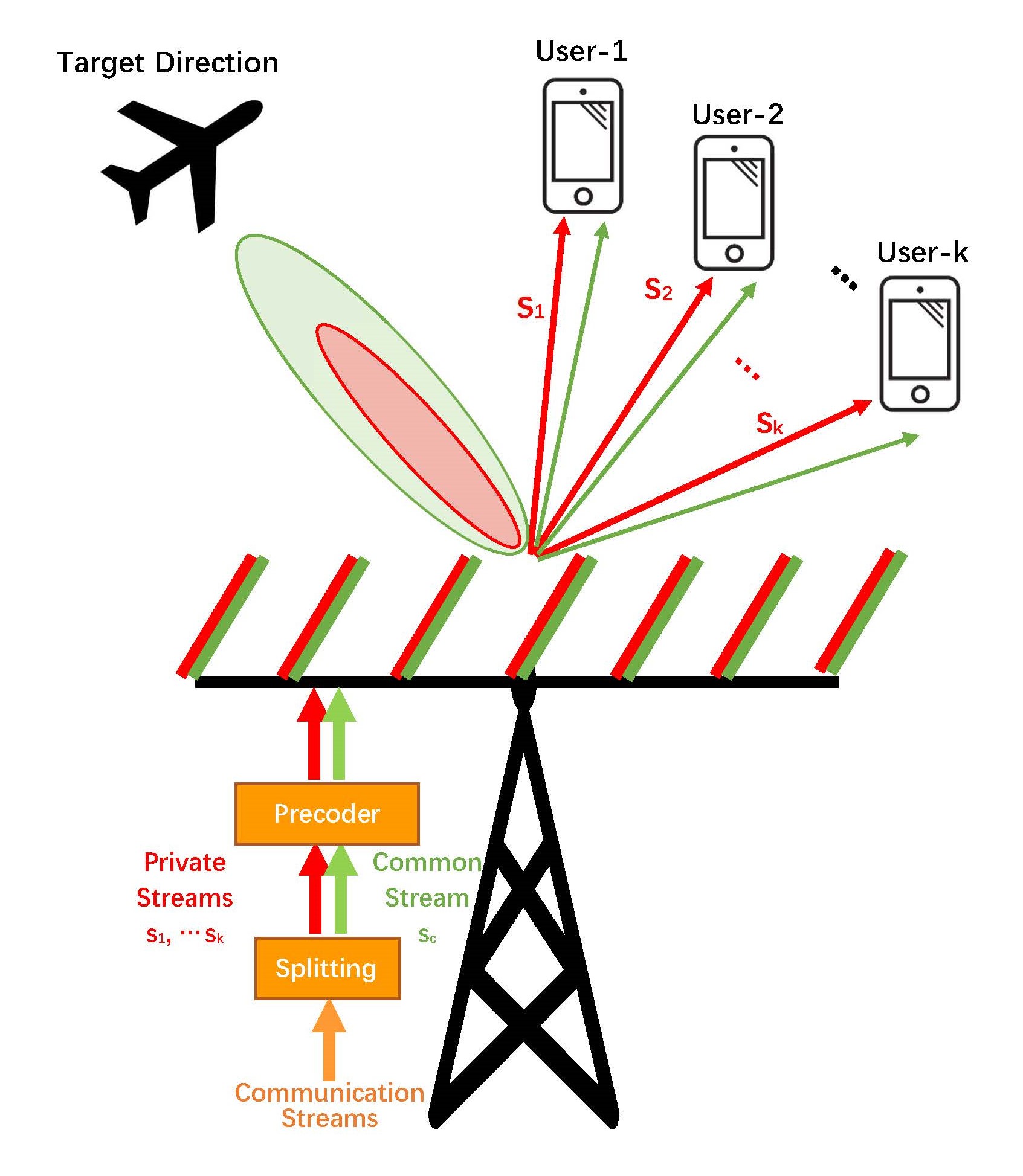
In this work, we consider a downlink multi-antenna RadCom system, which is equipped with a uniform linear array (ULA) of antennas and serves single-antenna communication users and one radar target. The communication users are indexed by . The schematic diagram of the proposed system is shown in Fig. 1.
II-A Rate-Splitting Preliminaries
Rate-splitting is a promising transmission technique to tackle numerous problems faced by modern MIMO wireless networks[13, 18]. The message of the th user is split into a common part and a private part , . The common parts of all users are jointly encoded into the common stream , while the private parts are respectively encoded into private streams . Then the data stream vector is linearly precoded using the precoder , where is the precoder of the common stream.
II-B MIMO Radar Beampattern Design
MIMO radar can transmit multiple probing signals that may be chosen freely via its antennas. Such waveform diversity enables superior capabilities compared with standard phased-array radar[5]. To achieve higher signal-to-noise ratio (SNR) for target tracking or narrow-beam scanning scenarios, and to avoid wasting probing power on either jammer locations or locations of uninteresting targets, a specially desired rather than a nominally omnidirectional MIMO radar beampattern should be achieved via correlated waveform design[19, 20, 21]. According to [20, 21], the beampattern design problem can be formulated in a more explicit way
| (1) |
where is the th azimuth angle grid among all grids, is the desired beampattern level at , is the covariance matrix of transmit waveforms , is the transmit steering vector, is the normalized distance (relative to wavelength) between adjacent array elements and refers to the vector constructed from the diagonal entries of the matrix. In (1), the objective function is to approximate the beampattern to the desired one via least squares, the first constraint ensures that every radar transmit antenna has the same average power with total power budget , and the second constraint ensures that is a semi-positive definite matrix.
II-C Joint RadCom Transmission System Design
Our multi-antenna RadCom system works as a RS-assisted BS, and simultaneously as a collocated MIMO radar, i.e., a mono-static radar. The transmit signal is formulated as
| (2) |
where is the common stream in the RS strategy, is the private stream for the th user, and is the time index. We only adopt precoded information streams as the transmit signal, but (2) meets the MIMO radar transmit signal model and thus are adequate for MIMO radar detecting according to [22]. Based on this transmit signal model, [22] derives that improving the SNR of the matched-filter output at the MIMO radar receivers, which is a key metric for radar detection, is equivalent to designing a desired radar transmit beampattern. As a result, we focus on increasing communication WSR and designing desired radar transmit beampattern in this paper.
Based on (2), the received signal at the th user is
| (3) | ||||
where is the channel vector between the RadCom system and the th user. It is assumed to be perfectly known at both the transmitter and the receivers. The received noise at the th user is modelled as a complex Gaussian random variable with zero mean and variance . Without loss of generality, we assume the noise variances all equal to 1, i.e., .
Following the decoding order in the literature of RS[14], each user first decodes the common stream by treating all private streams as interference. Therefore, the SINR for decoding at the th user is
| (4) |
After successfully decoding and subtracting it from , user- decodes the intended private stream by treating other private streams as interference. The SINR of decoding at user- is
| (5) |
The corresponding achievable rates of and at the th user are and . The common stream is decoded by all users. To ensure that all the users can successfully decode the common stream , the corresponding rate should not exceed
| (6) |
As is shared by users, we have , where is the portion of common rate at user- transmitting . The total achievable rate of user- contains the portion of common rate transmitting and the private rate transmitting .
In this work, we aim at designing communication precoder and message splits to maximize the WSR of downlink users and approximate the desired radar beampattern. Denote the weight allocated to user- as , the formulated optimization problem can be written as
| (7a) | ||||
| (7b) | ||||
| (7c) | ||||
| (7d) | ||||
| (7e) | ||||
where is the total transmit power budget of the whole RadCom system, is the common rate vector, the first part in (7a) maximizes the WSR from a communication perspective, while the second part ensures the probing beampattern approximates the desired pattern from a radar perspective, is the regularization parameter that balances the communication WSR and radar beampattern approximation, (7b) ensures each user can decode the common stream in RS, (7d) ensures the transmit average power of each antenna to be the same.
To show the advantage of RSMA in joint RadCom transmission, we consider the conventional multi-access SDMA based on multi-user linear precoding (MU-LP) in our RadCom system as a baseline. According to [18], the SDMA-based RadCom design is obtained by allocating zero power to the common stream of RSMA-based RadCom, which is formulated by replacing the first part of (7a) with and removing (7b).
III ADMM-based Method for Solving the Problem
Since (7) combines both communication and radar metrics, it is intuitive to think about alternately solving the communication and radar counterparts to find the optimal solution. In this section, we propose an iterative method based on ADMM to solve the nonconvex problem (7).
To give an explicit expression of the approach, we first denote a new vector that contains all variables , with . We then define
| (8) |
where is the diagonal matrix built from the entries within the bracket. We then further denote
| (9) |
and rewrite (7) in a tractable ADMM formulation
| (10) |
where is introduced as a new variable,
| (11) |
| (12) |
is the indicator function of the communication feasible set , is the indicator function of radar feasible set .
(10) can be solved by iterating the following updates
| (13) | ||||
| (14) | ||||
| (15) |
where with as the scaled dual variable. Here we write the ADMM expression in a real-valued way according to [23] to avoid confusions, letting , , , where , respectively mean extracting real and imaginary parts. It’s worth noting that this is just a different expression for the same problem to rigorously meet the definition of ADMM [24].
Then we present how to solve (13) and (14) in each ADMM iteration.The -update (13) is first equivalently rewritten in a tractable manner
| (16) |
This problem can be reformulated with Weighted Minimized Mean Square Errors (WMMSE) approach and solved through the WMMSE-based Alternating Optimization (AO) algorithm following [25].
The -update (14) is fully formulated as
| (17) |
Here , , where is the th element in , and the selection matrix is defined as
| (18) |
(17) is apparently non-convex, but can be solved by general Semidefinite Relaxation (SDR) method referring to [23, 26]. We summarize the ADMM-based method to solve problem (7) in Algorithm 1, where and are the primal and dual residuals. Similarly, the SDMA-based RadCom problem can be solved via the proposed ADMM-based algorithm in this section. In the simulations, we see that the proposed solving method always converges within tens of iterations.
IV Numerical Results
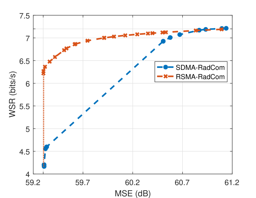
In this part, numerical results are provided to validate the performance of the proposed RadCom transmission design. We assume , the noise power at each user is . We consider a simple case in this paper, where , , . The RadCom system employs a ULA with half-wavelength spacing, i.e., . We randomly generate a pair of channel vectors obeying the i.i.d. standard complex Gaussian distribution, and use the specific channels in all the following experiments. The azimuth angle of the radar target of interest is 0°. We initialize randomly obeying standard complex Gaussian distribution, , where , , and is designed through Maximum Ratio Combining (MRC) method following [14]. Then the initialization , and can be obtained according to Section III. The stopping criterion in Algorithm 1 is . We denote the jointly designed RadCom transmission based on RSMA and SDMA strategies respectively as RSMA-RadCom and SDMA-RadCom. We set the same channel vectors, desired beampattern and regularization parameter in Fig. 5-Fig. 5 to compare both methods explicitly.
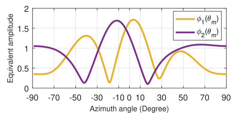
In Fig. 5, we first show the equivalent amplitude of each channel vector corresponding to each steering vector at in the beampattern. The amplitude is defined as . Fig. 5 equivalently reflects each user’s desired beampattern. It demonstrates that both users desire relatively high power near 0°, where the radar also desires a power peak.
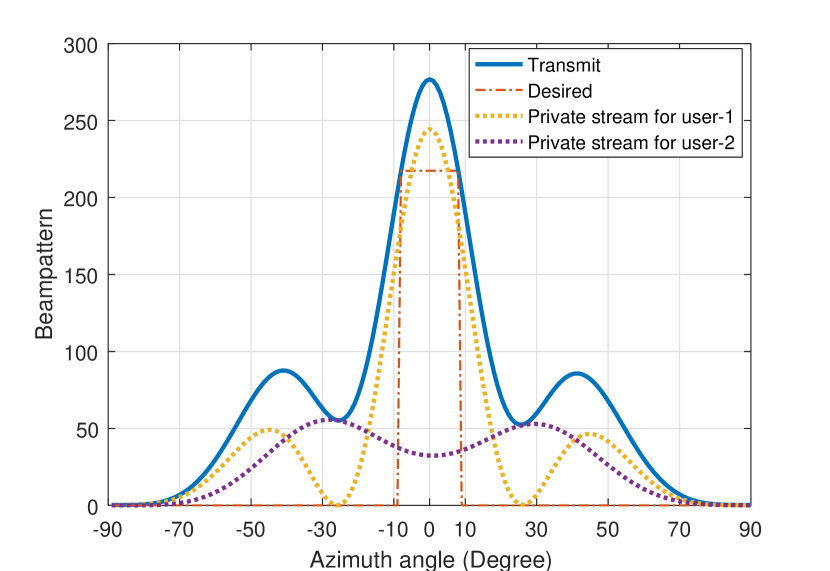
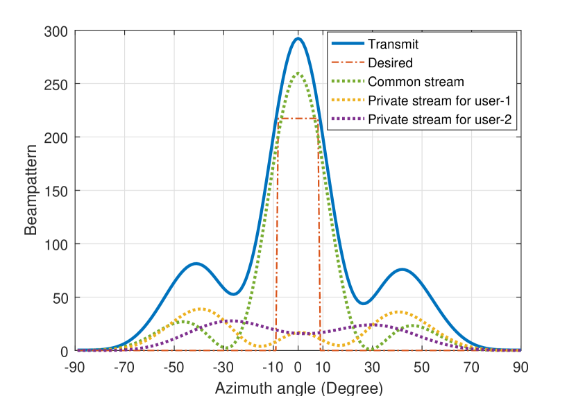
We then compare the transmit beampattern of RSMA-RadCom and SDMA-RadCom in Fig. 5 and Fig. 5. The beampatterns of the precoded common stream and private streams are respectively displayed so as to show the contributions of all streams to the RadCom transmit beampattern. We can see from Fig. 5 that SDMA-RadCom forces the private stream to user-1 to contribute more to the radar’s desired beam at 0°, as user-1 desires more power than user-2 at this angle. Although this strategy meets the radar’s requirement, the high power of user-1’s stream at 0° inevitably causes strong interference to user-2. However, from Fig. 5, we can see that the common stream instead takes the task of forming a beam at 0°. This is reasonable as the common stream benefits both users at 0°, which avoids the strong interference imposed by one user’s stream upon the other in SDMA-RadCom. This indicates that introducing the common stream better mitigates the interference between users caused by the radar’s beampattern requirement, which also explains why the beam peak at 0° and WSR of RSMA-RadCom are both higher than SDMA-RadCom.
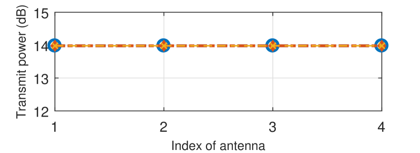
Fig. 5 shows the average power of each antenna, which verifies that the ADMM-based method reaches a high-quality solution to meet the average power constraint (7d) with a full use of the power budget . Table I analyses the rates achieved by RSMA-RadCom and SDMA-RadCom in this scenario. It displays that RSMA-RadCom has higher WSR and the common stream makes considerable contributions.
| WSR | |||||
|---|---|---|---|---|---|
| RSMA- | 5.2894 | 1.3454 | 3.9332 | 1.3454 | 5.9567 |
| RadCom | |||||
| SDMA- | 7.9120 | - | 0.5098 | - | 4.2109 |
| RadCom |
Fig. 6 is the tradeoff achieved by both RSMA-RadCom and SDMA-RadCom, which is obtained by varying while keeping other settings the same. Obviously, Fig. 6 further shows that RSMA-RadCom achieves a considerably better tradeoff than SDMA-RadCom in this scenario.
V Conclusion
To conclude, we propose a multi-antenna RSMA-RadCom system that functions both as a BS communicating with users and a radar detecting targets in specific azimuth angles of interest. We are the first to study maximizing WSR and approximating desired radar beampattern under the average power constraint of each antenna in the multi-antenna RadCom system. An ADMM-based method with WMMSE-based AO algorithm and SDR algorithm is proposed to solve the non-convex problem. Numerical results show that RSMA-RadCom achieves a better tradeoff compared with SDMA-RadCom in a specific scenario. This results from the creation of the common stream, which effectively mitigates interference especially at the transmit beampattern angles where we desire peaks. We can thus conclude that RSMA is a more powerful strategy when applied to multi-antenna RadCom design. However, different channel vectors may lead to different radar-communication tradeoff, which means further research is needed to fully evaluate the advantage of RMSA applied in RadCom in a variety of channel conditions.
References
- [1] H. Griffiths, L. Cohen, S. Watts, E. Mokole, C. Baker, M. Wicks, and S. Blunt, “Radar spectrum engineering and management: Technical and regulatory issues,” Proceedings of the IEEE, vol. 103, no. 1, pp. 85–102, Jan 2015.
- [2] A. Aubry, V. Carotenuto, A. De Maio, A. Farina, and L. Pallotta, “Optimization theory-based radar waveform design for spectrally dense environments,” IEEE Aerospace and Electronic Systems Magazine, vol. 31, no. 12, pp. 14–25, 2016.
- [3] B. Tang and J. Liang, “Efficient algorithms for synthesizing probing waveforms with desired spectral shapes,” IEEE Transactions on Aerospace and Electronic Systems, vol. 55, no. 3, pp. 1174–1189, June 2019.
- [4] L. Zheng, M. Lops, X. Wang, and E. Grossi, “Joint design of overlaid communication systems and pulsed radars,” IEEE Transactions on Signal Processing, vol. 66, no. 1, pp. 139–154, 2018.
- [5] J. Li and P. Stoica, “MIMO radar with colocated antennas,” IEEE Signal Processing Magazine, vol. 24, no. 5, pp. 106–114, 2007.
- [6] J. Qian, M. Lops, L. Zheng, X. Wang, and Z. He, “Joint system design for coexistence of MIMO radar and MIMO communication,” IEEE Transactions on Signal Processing, vol. 66, no. 13, pp. 3504–3519, 2018.
- [7] G. N. Saddik, R. S. Singh, and E. R. Brown, “Ultra-wideband multifunctional communications/radar system,” IEEE Transactions on Microwave Theory and Techniques, vol. 55, no. 7, pp. 1431–1437, 2007.
- [8] C. Sturm and W. Wiesbeck, “Waveform design and signal processing aspects for fusion of wireless communications and radar sensing,” Proceedings of the IEEE, vol. 99, no. 7, pp. 1236–1259, 2011.
- [9] A. Hassanien, M. G. Amin, Y. D. Zhang, and F. Ahmad, “Dual-function radar-communications: Information embedding using sidelobe control and waveform diversity,” IEEE Transactions on Signal Processing, vol. 64, no. 8, pp. 2168–2181, 2015.
- [10] ——, “Phase-modulation based dual-function radar-communications,” IET Radar, Sonar & Navigation, vol. 10, no. 8, pp. 1411–1421, 2016.
- [11] F. Liu, C. Masouros, A. Li, H. Sun, and L. Hanzo, “MU-MIMO communications with MIMO radar: From co-existence to joint transmission,” IEEE Transactions on Wireless Communications, vol. 17, no. 4, pp. 2755–2770, 2018.
- [12] F. Liu, L. Zhou, C. Masouros, A. Li, W. Luo, and A. Petropulu, “Toward dual-functional radar-communication systems: Optimal waveform design,” IEEE Transactions on Signal Processing, vol. 66, no. 16, pp. 4264–4279, 2018.
- [13] B. Clerckx, H. Joudeh, C. Hao, M. Dai, and B. Rassouli, “Rate splitting for MIMO wireless networks: a promising PHY-layer strategy for LTE evolution,” IEEE Communications Magazine, vol. 54, no. 5, pp. 98–105, May 2016.
- [14] H. Joudeh and B. Clerckx, “Sum-rate maximization for linearly precoded downlink multiuser MISO systems with partial CSIT: A rate-splitting approach,” IEEE Transactions on Communications, vol. 64, no. 11, pp. 4847–4861, 2016.
- [15] M. Dai, B. Clerckx, D. Gesbert, and G. Caire, “A rate splitting strategy for massive MIMO with imperfect CSIT,” IEEE Transactions on Wireless Communications, vol. 15, no. 7, pp. 4611–4624, 2016.
- [16] H. Joudeh and B. Clerckx, “Rate-splitting for max-min fair multigroup multicast beamforming in overloaded systems,” IEEE Transactions on Wireless Communications, vol. 16, no. 11, pp. 7276–7289, 2017.
- [17] Y. Mao, B. Clerckx, and V. O. K. Li, “Rate-splitting for multi-antenna non-orthogonal unicast and multicast transmission: Spectral and energy efficiency analysis,” IEEE Transactions on Communications, vol. 67, no. 12, pp. 8754–8770, Dec 2019.
- [18] Y. Mao, B. Clerckx, and V. O. Li, “Rate-splitting multiple access for downlink communication systems: bridging, generalizing, and outperforming SDMA and NOMA,” EURASIP journal on wireless communications and networking, vol. 2018, no. 1, p. 133, 2018.
- [19] J. Li, L. Xu, P. Stoica, K. W. Forsythe, and D. W. Bliss, “Range compression and waveform optimization for MIMO radar: a Cramer–Rao bound based study,” IEEE Transactions on Signal Processing, vol. 56, no. 1, pp. 218–232, 2007.
- [20] D. R. Fuhrmann and G. San Antonio, “Transmit beamforming for MIMO radar systems using signal cross-correlation,” IEEE Transactions on Aerospace and Electronic Systems, vol. 44, no. 1, pp. 171–186, 2008.
- [21] P. Stoica, J. Li, and Y. Xie, “On probing signal design for MIMO radar,” IEEE Transactions on Signal Processing, vol. 55, no. 8, pp. 4151–4161, 2007.
- [22] B. Friedlander, “On transmit beamforming for mimo radar,” IEEE Transactions on Aerospace and Electronic Systems, vol. 48, no. 4, pp. 3376–3388, October 2012.
- [23] W.-K. Ma, “Semidefinite relaxation of quadratic optimization problems and applications,” IEEE Signal Processing Magazine, vol. 1053, no. 5888/10, 2010.
- [24] S. Boyd, N. Parikh, E. Chu, B. Peleato, and J. Eckstein, “Distributed optimization and statistical learning via the alternating direction method of multipliers,” Foundations and Trends® in Machine Learning, vol. 3, no. 1, pp. 1–122, 2011. [Online]. Available: http://dx.doi.org/10.1561/2200000016
- [25] Y. Mao, B. Clerckx, and V. O. K. Li, “Rate-splitting for multi-user multi-antenna wireless information and power transfer,” in 2019 IEEE 20th International Workshop on Signal Processing Advances in Wireless Communications (SPAWC), July 2019, pp. 1–5.
- [26] S. Boyd, L. El Ghaoui, E. Feron, and V. Balakrishnan, Linear matrix inequalities in system and control theory. Siam, 1994, vol. 15.