Formal Approach for the Verification of Onboard
Autonomous
Functions in Observation Satellites
Abstract
We propose a new approach for modelling the functional behaviour of an Earth observation satellite. We leverage this approach in order to develop a safety critical software, a “telecommand verifier”, that is in charge of checking onboard whether a sequence of instructions is safe for execution. This new service is needed in order to add more autonomy to satellites. To do so, we propose a new Domain Specific Modelling Language and the toolchain required for integration into an embedded software. This framework is based on the composition of deterministic finite state machines with safety conditions, timeouts, and transitions that accept durations as a parameter. It is able to generate code in the synchronous programming language Lustre from a high-level specification of the satellite. This gives a formal way to derive an event-based algorithm simulating the execution of telecommand sequence and, thereupon, a provably correct onboard verifier.
Keywords— Formal methods, Safety, Autonomous systems, Space systems
1 Introduction
Over the last decade, autonomy was progressively introduced in most technological domains. This can be explained by the necessity to add “autonomous decisions making” capabilities to implement new functionalities or to enhance existing ones. However, the architects of critical systems tend to oppose this trend, which increases the complexity of validation stages and therefore implies significantly higher costs to reach the required levels of safety.
In the space industry, most satellites are yet entirely commanded from the ground, through pre-computed static mission plan which definitely leaves room for onboard optimization.
Introducing autonomy in observation satellites would improve their flexibility and responsiveness. The associated benefits could range from integrating urgent requests in an ongoing plan, to reducing the memory footprint thanks to a higher compression of cloudy images. This can be achieved by allowing onboard software to modify its own sequence of commands. However, it should be done without impairing its safety. This is why we carefully consider the validation of an onboard software able to update the satellite plan by itself.
At present, observation satellites are mostly teleoperated; they execute sequences of low level, time-tagged instructions, named Telecommands (TC), that are generated and verified on the ground before being uploaded. These TC sequences are thoroughly tested to prevent the occurrence of events that may trigger the fail-safe mechanisms of the satellite. Indeed, any occurrence of such feared event could result in the following chain of actions: interrupting the execution of ongoing mission plan, shutting down all non essential systems, directing the satellite solar panels towards the sun and waiting for the satellite to be taken over by satellite control experts. This event should be avoided at all costs, since recovery may take hours to days, during which the mission of the satellite is interrupted, resulting in substantial shortfall.
A TC sequence can contains hundreds up to thousands of instructions (depending on the covered time span) and can only be uploaded at infrequent intervals (typically four to eight times a day). This situation has several disadvantages. In particular, it makes it impossible to change the satellite plan quickly, for example to add a new, urgent mission element or to react to the detection of clouds that could obscure the ground. In addition, this mode of operation where the whole set of elementary TCs is uploaded involves significant transmission of data at low rate, which prevents the use of small ground stations.
One solution to these problems is to transmit higher level instructions to the satellite—what we call Synthetic Telecommands (STC) in Sect. 2. We can then instruct the flight software to interpret these commands and modify its execution plan accordingly with the proper anticipation time. A key element to implement this new approach is to provide a software toolchain able to “expand” an STC into low-level telecommands (with the appropriate time-tags) and then “merge” the result into the sequence of instructions that are already planned.
Given the criticality of the application, we seek to formally validate the algorithms and software used in this process. This is essentially a multi-constraints problem, since a valid sequence of TC must take into account strict timing constraints (respect of deadlines); constraints on the geometry of the satellite (e.g. attitude angles during image acquisition); priorities assigned to the different missions; constraints on the memory capacity, etc.
Validating and verifying this kind of software with the reliability standards and quality level expected from space missions is expensive and time-consuming. It mainly relies on extensive test campaigns, with heavy simulations that can only be performed on ground. Throughout the article, we propose to use a simple software architecture that relies on a Telecommand Verifier. The goal of this small piece of software is to accept or reject a sequence of telecommands before its execution. On the satellite processors, we may not rely on extensive tests and simulation, due to the limited computational power, which is why a new approach is required for the onboard verification of TC sequence. However, our approach is not necessarily limited to onboard verification: it could also replace specific parts of the validation process performed on the ground, which may result in significant costs reductions. More globally, one of our goal is to evaluate the use of formal methods, such as static analysis tools and deductive verification of programs, to validate key elements of the software architecture of a satellite.
In order to reach the level of confidence required in critical systems, we also need to prove that this verifier is sound, meaning that every sequence of TC vetted should be safe for execution by the satellite controller (or at least as safe as a sequence generated on the ground). Lastly, we are also interested by the completeness of our verifier, in the sense that it should accept as many sequences as possible.
This approach is comparable to what appears in some software frameworks
that support remote code execution, such as the Java virtual machine [13], where a bytecode verifier is in charge
of checking new code before it is executed. Our approach shares the
same advantages. First of all, it reduces the size of the critical
software components that need to be proven correct (the “trusted
computing base”). Also, it enables a modular approach, since
we can easily change the range and the behaviour of our set of
STCs without the need to modify the rest of our software platform.
Contributions and structure of the paper. We start by giving a bird’s-eye view of the architecture of a Low Earth Orbit observation satellite, which provides the main target of our framework. Next, in Sect. 3, we motivate the need for adding more autonomy and describe our approach for validating the execution of “dynamic plans”, directly onboard, by using a telecommand verifier. Our main contribution is a new method for deriving this critical software from a high-level description of the behaviour of a satellite. To this end, we define a dedicated, formal modelling language, called CSM (see Sect. 4), and explain how we can reduce the problem of accepting a sequence of TC to an acceptance problem (in the sense of formal languages theory) in the CSM model. We have applied this approach on a realistic space system, that corresponds to the AGATA technological platform specification, and give a complete high-level representation of the obtained model in the diagram of Fig. 2. This model lends itself naturally to an implementation into a synchronous language, such as Lustre [9]. In Sect. 6 and 7, we show how we can exploit the program resulting from the compilation of Lustre and discuss the implications on the safety assessment that can be made to strengthen our claim that the verifier is sound and valid.
2 High-Level Description of an Observation Satellite
We have experimented our approach with satellites designed for Earth
observation from Low Earth Orbit. The scope of our case study so far
is limited to the satellite model capabilities of the AGATA
technological platform specification [4], which
is able to run decision algorithms and flight software more easily
than a complete satellite simulator. Nevertheless, we designed our
approach with a focus on extensibility and we believe that most of our
work could be transposed to
other kinds of satellites.
Equipments. We can describe a satellite based on the set of equipments that it
carries. In our context, the primary mission-related instrument is
an optical imager (INSTRUMENT), tasked with capturing images of the
ground. There is also a collection of “smaller” equipments, such as
memory banks (MEMORY), a compressor for storage optimisation
(COMPRESSOR), as well as a signal modulator and a signal amplifier,
used for transmitting data to the ground stations (MODULATOR and
AMPLIFIER). All these equipments will appear as separate components in
our
formal model, which is summarized in Fig. 2.
Functions. Apart from these physical elements, the behaviour of the satellite can be reduced to the management of several high-level functions. The main purpose of the observation satellite mission is the acquisition of data (images in our case), using the payload (an optical instrument in our case). These images stored in the satellite memory must be collected on the ground, using the download function. The satellite memory can then be freed using the data or file deletion function, to allow the acquisition of new images. Each of these higher-level functions will also correspond to a component in our model, under the names RECORD (for acquisition), DOWNLOAD and ERASE.
These functions require the satellite to always be in the right
position and orientation, which is handled by the modes of a
transverse function: the Attitude and Orbit Control System
(AOCS). For instance, in the Geocentric Attitude Pointing mode
(GAP), the satellite main axis is roughly oriented towards the
Earth center, in order to ease data download. Conversely, during an
acquisition, the AOCS must remain in a Custom Attitude Pointing mode
(CAP), to precisely track
the proper footprint on the Earth. The third main mode of the AOCS is
called SUP (for SUn Pointing attitude), and is used to point at
the sun and maximize the battery charge from the solar
panels. Each mode will correspond to a state in the AOCS component.
Onboard Computer and Telecommands. The last component of this architecture is the onboard satellite controller, which provides the satellite’s processing capability. The controller host the onboard software (OBSW) that is in charge of dispatching orders to the instruments, the communication between vital functions of the satellites, and the synchronization and execution of telecommands.
The OBSW can be abstracted as a machine that reads its orders from a sequence of TC and send resulting commands to the equipments at the right date. In our context, we can assume that the onboard software is a periodic task and that each equipment and function can communicate with the OBSW only at the beginning of each cycle.
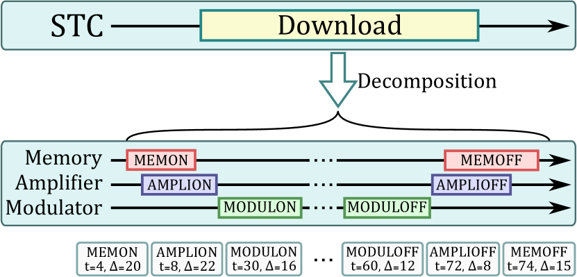
Most telecommands are only required to set each equipment of the satellite in the right mode (typically: switched-on), before performing a main function. Therefore, in our approach, we consider only the few high-level requests that are relevant: Acquisition, Download, Deletion and Maneuver. On this basis, we introduced the notion of Synthetic TeleCommands (STCs), that can be decomposed into a sequence of elementary TCs required to perform the corresponding function.
We give an example of a sequence of six TCs in Fig. 1 that
corresponds to a request (an STC) for downloading an image from memory
to the ground. (In the most general cases, an STC can correspond to up
to eleven TCs.) Essentially, it is a sequence of commands of the kind
...MODULON(t=30,=16)...
with an indication of the absolute date (t) and duration
() of each TC. We do not consider other types of parameters
here, such as the memory address where to read data or the position
and the geometry for an image acquisition.
As a first approximation, a sequence of TC is a timed word.
But not all sequences are safe for execution. Indeed, functions and
instruments are closely intertwined together. This gives rise to
several constraints that relate the states of the instruments with the
possible steps of a function. For example, it is unsafe to start
imaging if the satellite is pointed at the sun (when AOCS is in
“state” SUP) since it would expose the optical instrument to
potential damages.
Some functions also introduce timeouts or timing constraints between
the occurrence of events. For instance, transmitting an image requires
to switch the modulator to state ON, which takes a specific
time related to physical constraints (defined as a constant
DURATION_MODULON in the
documentation).
In the following, we develop a formal model that can be used to describe, in an unambiguous way, whether a sequence of TC is safe. Our main objective is to derive a TC verifier from this specification. The role of this critical software element is to reject TC sequences that could harm the satellite’s mission.
In the next section, we motivate the notion of STC and explain why the STC decomposition (and the verification of the result) should take place onboard.
3 Motivation of our Approach
The addition of Synthetic TC is a new proposal that is motivated as a way to introduce more autonomy, allowing a satellite to perform some of its mission planning onboard. It also reduces the amount (and granularity) of data to be transmitted between the ground and the board. This extension has an impact on the dependability of the system. Indeed, the onboard decomposition of an STC is not unique since it depends on multiple factors, such as equipments status and variables (e.g. attitude precision), or the chaining of sequences of STCs. The latter may result in optimization such as keeping an equipment ON if it will be used in consecutive STCs. Therefore, it is not always feasible to test all the possible results of an STC decomposition on the ground, before uploading it for execution.
Actually, our approach is not specifically tailored to the way STCs are exploited by the onboard software. This allows us to introduce new extensions incrementally. For instance, in a first class of autonomy, the satellite may (only) dynamically insert new TCs in its work plan, depending on the STC decomposition strategy. But we may also envision higher classes of autonomy where a satellite may choose to schedule or delete an STC dynamically, depending on unpredictable chains of events. For instance, the detection of clouds in an image may lead to its deletion and save memory space, for additional pictures to be captured. Finally, we can even consider cases where the choice depends on the result of some (black-box) decision algorithm. A discussion on autonomy in the AGATA platform that we target can be found in [16].
The potential optimizations or the ability to consider onboard events and modify the plan accordingly, when out of reach of a ground station, are among the strongest arguments in favour of performing the STC decomposition on board. However, its result should be safe for execution by the satellite, to ensure the continuity of the mission. A way to reduce the complexity of this task is to verify the sequences of TCs that result from these decompositions. Nevertheless, several issues must be solved in order to build a TC sequence verifier.
In the following sections, we describe the behaviour of the satellite
using a domain-specific notation and we use this model to define what
is an admissible
sequence of TCs. For the purpose of this work, we compare our
behavioural model of the satellite with a System
Requirements Specification document (SRS) that lists the expected functions
and features related to the operation of the satellite. For instance,
the particular behaviour of the modulator system that we mentioned
above, corresponds to requirement REQ_DOWN_02 below, which also
entails that the
signal amplifier must be ON when we power-on the modulator:
REQ_DOWN_02: Switch modulator to ON.
|
||
The modulator is ON after duration DURATION_MODULON
|
||
| initial condition = Amplifier is ON |
Overall, we need to define exactly what it means that a TC sequence is admissible. This property may depend on the state of the satellite when the execution starts. Hence we need to define what are the “reachable states” of the satellite, and what is the effect of executing a command from a state. Finally, we want to provide an (operational) method to effectively accept or refuse a TC sequence.
We provide a solution to each of these problems. Our main idea is to use an automata-based framework to describe the behaviour of each equipment and function. Then the behaviour of the whole system can be defined as the symbolic composition of all our automata with a component that represents the onboard software (OBSW). To this end, we propose a model in which transitions can be triggered by a command (modelling the reception of an order from the controller) or by a timeout (modelling the end of an activity). We also provide a way to associate an invariant to a state (a boolean expression on the states of the system) that can trigger an error when a condition is not met. In this context, invariants correspond to error cases identified in the specification.
4 Formal Models
In the following, we describe the formal models used in our work. We provide two different ways (or notations) to express the same model: a graphical notation that is more suited for code review; then an equivalent textual notation, that is easier to handle with tools, for code generation and code analysis activities.
We use the textual syntax as our “pivot” notation and provide a way to generate the graphical model automatically from the code in our toolchain. The main purpose of the graphical model is to ease the review of the model and the traceability with the SRS.
4.1 Graphical Notation
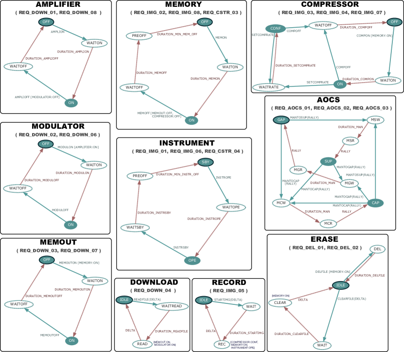
We display the complete graphical model of the satellite in Fig. 2. Each component (equipment or function) is named and appears in the form of a finite state machine. We also list, in each case, the identifiers of the requirements in the SRS that relates to the behaviour of the component.
We distinguish steady states (plain lines)—where we await orders from the controller—from transient states (dashed), where we await for the end of a timeout. In this case, a timeout is modelled by an outgoing, dotted transition associated with a duration. Each component has a unique initial state which is necessarily steady. It is displayed using a thick black border.
Other conventions of our model include: there is always at least one transient state between two steady states; each transient state is the source of exactly one transition (a timeout). This reflects some strong invariants in the conception of a satellite: (1) it is not possible to change state without receiving a TC from the onboard controller; (2) the change of state is deterministic and the OBSW can always predict which steady state a TC should switch to (after some finite duration).
If we focus on the automaton for the Modulator equipment, we
see that it can be in only two possible steady states: the initial
state, OFF, and the ON state. Another information given by
the diagram is that only the MODULON telecommand can cause a
transition out of the steady state OFF; which results in the
Modulator staying in the transient state WAITON for a (constant)
duration equal to DURATION_MODULON. This information
corresponds to requirement REQ_DOWN_02 of the SRS, that we used
as an example in the previous section.
In order to represent constraints between equipments or functions, we also define a notation for invariants—displayed inside square brackets—that can be associated to either telecommands (I) or specific states (II) as follows:
-
(I)
Invariants on telecommands are displayed as transition guards that must be true when the TC is received, otherwise the whole TC sequence is rejected (failures are permanent). For instance, the telecommand MODULON is valid only when AMPLIFIER is in state ON (during the cycle when the TC was dispatched). This is the last element in requirement
REQ_DOWN_02. -
(II)
For invariants on states, the implicit behaviour is that a component immediately triggers an error when the invariant is false. An example can be found on the transient state READ of the Download automaton. Intuitively, this means that the Memory Output and the Modulator should stay ON the whole time we are downloading an image from the satellite to the ground.
One of the reasons that explain the conciseness of this graphical notation is that we do not need to make explicit many of the “error conditions” of the satellite behaviour. Indeed, we assume an error when we receive a telecommand that cannot be processed. For example, it is an error if the Modulator receives a MODULON command while in state ON. Adding these kinds of error invariants, for instance by adding a dedicated “sink state”, would greatly overload our diagrams.
We can also remark that the OBSW is the only component, defined in Sect. 2, that is not explicitly represented in the model. This is because the behaviour of the onboard controller is fixed. Intuitively, we can think of the OBSW as the component responsible for dispatching the TC and checking that the invariants hold.
The resulting model is not far from other timed formal languages, such as Timed Automata [1] for example. One major difference, though, is that we may sometimes receive a duration together with a TC. This is the case in the transition on telecommand CLEARFILE of the Erase component/function, originating from state IDLE. This formal parameter, called DELTA here, models the fact that the operation of deleting a file is not performed in constant time, but depends on its actual size (number of memory sectors that need to be cleared). In practice, the value of DELTA is part of the TC that is dispatched from the onboard controller to the Erase function and is available to the OBSW when we check the sequence of TC.
4.2 Compact Satellite Model
To simplify our tooling, we designed an equivalent textual syntax; a programming language called the Compact Satellite Model, or CSM for short. This language can be used to formally describe satellite requirements. As an example, we provide the CSM specification of the Modulator and Erase functions in Listing 1.
In the CSM, each component definition starts with the keyword block followed by the declaration of the initial state—given after the keyword init. This state usually represents the equipment or the function when not in use (OFF or IDLE in our running example). The rest of the block is a list of transitions and invariants declarations.
A transition is defined with the keyword tc and declares a sequence, between parenthesis, that starts and ends with a steady state (the source and destination states) and that enumerates all the possible transient states in-between, in order. The delays needed to exit these transient states are given between braces and can refer to durations that are listed in the SRS (such as {DURATION_MODULON} for instance). This notation makes explicit the constraint that there is at most one sequence of “transient transitions” between every pair of steady states (for a given TC).
We make a distinction between regular transitions, tc, and delta telecommands, declared with the keyword tcd, whose timeout depends on a duration that is passed as a parameter of the TC. We have already described this behaviour in previous section, for the transition CLEARFILE of the Erase component.
Finally, we use keywords guard for declaring a guard on telecommands and inv for declaring a guard on states, like in cases (I) and (II) discussed with the graphical notation. Invariants are the reason why we may not always replace a (deterministic) sequence of timeouts with a single transition. For instance, if we look at the sequence of transient states visited after a CLEARFILE telecommand in component Erase, we see that invariant [MEMORY:ON] applies in state CLEAR, but not in state WAIT. This means that it is not forbidden to request a file deletion when the Memory is OFF, but is should be ON before the Erase function reaches the CLEAR state.
Finally, as in the graphical model, the traceability between code and requirements is made simple by the modularity of the language: we can specify a list of requirements identifier inside the comments of each block (line beginning with the symbol #).
4.3 Design Principles for the CSM
Many of the decisions taken when defining our modelling language are based on the following design principles:
-
1.
The model should be readable by any satellite expert that took part in writing the satellite specification document, without any particular knowledge of formal methods.
-
2.
Building the CSM model from the initial, informal specification should not be too tedious or unnecessarily complex.
-
3.
Building the CSM model should ideally not require more time than writing the usual spreadsheet, or document in tabular format, used to gather system requirements.
The first design principle motivates the choice of an ad-hoc formalism—a Domain Specific Modelling Language (DSML)—since it does not require the user to be familiar with a pre-existing technology. This helps the verification process, since the formal model should be reviewed by domain experts, and not software architects. This also motivates our choice of a notation that is close to “state machines”, since the SRS already includes state diagrams in some of their requirements.
These two design principle help avoid errors and reduce the time spent by architects on mindless, repetitive tasks. For instance, the last design principle implies that the CSM model should not contain more details than the SRS and therefore prevent from adding non-essential requirements or invariants. These goals are achieved by designing a language that is tailored towards the exact level of abstraction needed for the task and that integrates the specificities of our application domain. For example, we rely on the fact that a satellite equipment is inherently time deterministic (it can only accept orders coming from the onboard software, OBSW, at a precise date, and the OBSW can predict in which state every equipment and function will be in the future). This can also be observed in our very lightweight treatment of errors. This would not be possible with a “general purpose” behavioural specification language which, by definition, requires every details to be made explicit.
There are other incentives for using a dedicated and “agnostic” approach, that is unbiased towards any particular technology. In particular, it may help us take into account changes in the satellite architecture more easily. Moreover, we could imagine using the CSM model for something else than deriving our TC verifier; we mention a possible use for generating covering tests in Sect. 7. Finally, the choice of a dedicated language for behavioural specification can shield us from problems that could arise if we decide to change our target platform. For example, in an initial prototype of our approach, we experimented with a toolchain targeting a subset of the C language, the ANSI C Specification Language (ACSL), and a deductive verification approach based on the use of Frama-C [12]. We eventually decided to select Lustre for our work, since the generated program invariants (the ACSL part) were too complex in our use case.
5 Verification of TC Sequence
The core of our approach relies on the fact that we can express the problem of accepting a TC sequence as a (timed-word) acceptance problem on the CSM model. Indeed, a sequence of TC can be interpreted as an execution trace of the whole model in which all commands are triggered and no errors are produced. As a consequence, a TC verifier can be directly derived from this definition by implementing an interpreter and running it on the TC sequence. In our work, we define the interpreter using the synchronous language Lustre and extract an executable from it by compiling the result into C code.
The Compact Satellite Model depicted in Sect. 4.2 does not support any acceptance function as is. However, most of its design is based on classical automata formalisms, such as Timed Automata [1]; the Discrete Event System specification (DEVS) of [5]; or the Timed Transition Systems of [10]. For instance, like in the DEVS model, every state is associated with a given lifespan (which is infinite in the case of steady states) and there is a single transition associated with the event of a state reaching its lifespan. Therefore we can easily define a notion of (timed) trace acceptance for CSM.
Many specificities of our framework make this definition simpler. First, every TC targets only one particular equipment or function (there is no synchronization between components). Also, interactions between equipments and functions are always mediated by the OBSW, that operates on a fixed cycle111The frequency of this cycle may be quite low. For instance, in the first generation of SPOT satellites, the frequency of the controller is of only .. Consequently, we can reason using a discrete time model, where each “tick” is synchronized with the clock of the controller. Finally, every timing constraint is punctual and can be expressed as a number of execution cycles (there is no uncertainty on the duration of an event and therefore no need to use time intervals).
On the other hand, we need to take into account timeouts situations (the fact that time elapses) and also the fact that several commands may be issued at the same date, and therefore that multiple components may trigger transitions simultaneously. Another major difference with other popular timed models is that some telecommands take a timeout (duration) as a parameter. This is the case, for instance, with the telecommand CLEARFILE, which takes a formal parameter (called DELTA) in the tcd transition of block ERASE in Listing 1. The value of this parameter, when the TC is executed, gives the duration that should be spent in state CLEAR before moving to IDLE (see Fig. 2). This means that we may possibly deal with an infinite number of transitions—one for each value of DELTA—even though, in practice, we could bound the duration parameters.
For the sake of brevity, we cannot give a complete and precise presentation of the formal semantics for the CSM language here. Let us just say that we have defined a structural operational semantics for the CSM based on a small step reduction relation (in the style typically used in concurrency semantics) and can define the meaning of a CSM model as a Labelled Transition System (LTS) with discrete transitions representing the evaluation of telecommands; internal (or silent) transitions representing local changes in the state of a component (typically the effect of a timeout); and “continuous” transitions representing the passage of time. With this semantics it is possible to prove that our CSM model of Fig. 2 is “time-deterministic”. Actually, for any system that meets the constraints listed in Sect. 4.1, we could prove that a given TC sequence corresponds to at most one path in the LTS; and situations of deadlocks means that the sequence should be rejected.
In this context, the executions (or traces) accepted by a CSM model are exactly the finite paths in its labelled transition system, starting from the initial state. It is not necessary to compute the whole LTS to test if a given TC sequence is admissible. We only need to “execute” the formal semantics and to check, at each step, that the invariants described in the CSM model are true. Also, we can easily extend this notion of acceptance to any given reachable state in the LTS (instead of only the initial state).
5.1 Choices of Operational Semantics
We can define two main categories of semantics for the CSM. A first possibility is to define a “cycle accurate” interpreter, in which we simulate the evolution of the system at each cycle. This corresponds to following each discrete transition in the LTS. If all events are accepted and constraints between automata are respected, the simulation continues; otherwise the sequence is rejected and we can report the last safe state of the system. This approach is easy to implement, but it may be sub-optimal.
Another possibility is to build a “discrete-event” interpreter, where we can simply skip to the next instant where a meaningful event occurs (a TC or a timeout). This can speed up the interpreter, but it requires to build a list combining TC start dates and computed timeouts, and to sort this list in increasing order.
We have experimented with the two approaches in our work. In each case, we can provide an encoding of the system model using a translation into the synchronous programming language Lustre. This process is made simple by the fact that we can encode each automata separately and compose them by combining together common events. We have mostly concentrated our efforts on the “cycle accurate” version of the TC verifier, since it leads to much simpler code and therefore is simpler to review during the safety assessment.
5.2 On the Unfolding of STC
In this work, we advocate an approach that is somewhat similar to the one of Proof-Carrying Code (PCC) [15], a software mechanism that allows a host system (a satellite in our case) to check that it is safe to execute a program supplied by an untrusted source.
It would not be realistic to develop a simple, onboard verifier at the level of synthetic telecommands. Basically, each STC can be compiled into a fixed sequence of TC. This is the simple part. Then we need to insert, or weave, the resulting sequence into the commands that are already scheduled by the onboard software. Inserting a TC sequence into an existing one is a difficult problem when you want to optimize the result. Indeed, even a slight change in the order of TC can have far-reaching consequences. For example, delaying the capture of an image because we have inserted a conflicting command may result in a longer time spent changing the orientation of the satellite (to compensate for the change in the direction that the AOCS needs to point to). Therefore the expansion of an STC is also a scheduling and planning problem, subject to multi-objective optimization constraints: we want to acquire a maximum number of usable images; while balancing the memory allocation; and taking into account the opportunities to download images that have already been taken. In order to be competitive with plans computed from the ground—that is to compute a schedule that is as close as possible to an “optimal” one—we need to use heuristics and techniques from Operational Research. And it will be very complex to prove the safety of such an STC unfolding and optimization engine.
In our solution, we separate the safety aspects of the problem from the computational one. We do not require any knowledge on the way a new TC schedule is computed from the previous one. We consider the result TC sequence as an “untrusted source”, to quote the PCC approach, and provide a mechanism to check that it is safe for execution.
6 Overview of our Framework
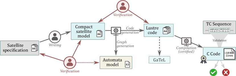
We describe our global approach with the diagram in Fig. 3. The starting point is a set of high-level requirements (in our example we have chosen the description of a satellite from the Spot-1 family). These requirements cover the main equipments of the satellite, as well as the AOCS modes and the mission-related functions that we described in Sect. 2: acquisition, download, memory management, etc.
The first step consists in deriving a CSM specification from the requirements. Each equipment should typically correspond to a different CSM block and each telecommand can be defined using the keywords tc and tcd. The associated durations are also used in these macro commands, as they will correspond to timeouts exiting a transient state. If an initial condition must be fulfilled, an inv or a guard should be built accordingly, as defined in Sect. 4.2. The resulting model remains very compact. For example, in our use case, the CSM of the whole satellite specification (three pages of requirements) fit into two pages of code.
Once the CSM is obtained, it is used as input by a code generator that can output both: (1) the graphical model in Graphviz’s DOT language [6]; and (2) a set of components written in the synchronous language Lustre that implements (time-compatible) “interpreters” for each block in the CSM.
The automata model preserves the modularity and compactness of the CSM and can be displayed on a single page. It can be used later on to ease and improve confidence during the verification process between CSM and specification. Concerning the Lustre code, we give a high-level view of the structure of the generated code below.
The last step in our framework is to derive the TC verifier by compiling the Lustre code. For this, we can use one of the many Lustre compiler that are currently available such as compiler that are formally verified [8] or even certified [3]. Our objective is to use a certified toolchain in order to reach the level of safety required in the space industry and to obtain a C program behaviourally equivalent to the Lustre code. We review the different parts of this framework again in Sect. 7, when we discuss safety issues,
6.1 Structure of the Generated Lustre
We generate a set of Lustre nodes (or blocks) that correspond to the components of the CSM model. Each node can read telecommands by looking at a specific signals (which are on when the command is called), and similarly with durations (interpreted as a signal that is on when a timeout ends). Every node (CSM component) can communicate with a central controller, which can be compared with the OBSW component described in Sect. 2, in charge of synchronizing the telecommands and of checking invariants between components. The composition of all these components can be used in a Lustre simulator, such as Luciole [7], to check the validity of a TC sequence against the specification.
Each node takes as input a dedicated list of telecommand signals and the corresponding duration parameters if any, and returns its current state. It handles its own local timers which are usually armed upon the reception of a telecommand, and is able to modify its return state accordingly. Finally, it is also responsible for verifying the compliance between current state and signals received. Each node has a dedicated error signal, connected to the OBSW node. It will return an error state if its structural constraints are not respected (for instance when a node receives a telecommand while not in the expected state).
The role of the OBSW node is to collect the distributed state of every equipment and function nodes in order to compute the global view of the system. This centralized state controller can be used for the verification of guards and invariants that involve multiple nodes.
The structure of the generated code reflects the modularity of the CSM specification. This is useful in our case since it means that we can review the generated code in a modular way; component by component.
7 Safety Assessment
This section focuses on the arguments that support our confidence on the TC verifier obtained with our framework.
One of our main objective is to derive a TC verifier, from a set of satellite requirements, while both: (1) increasing our confidence on the tool (for safety reasons); and (2) reducing as much as possible the need for a human review of the code (for limiting costs and development time).
To this end, we have designed the CSM language with the goal to limit, as much as possible, the semantic distance between requirements and specifications. While we still need to manually review the CSM code to check its compliance with the requirements, we are able to do this in only one day in our current use case. This is mainly achieved thanks to two complementary factors. First, the possibility to automatically generate a graphical representation from a CSM model222We could increase our confidence by “certifying” the generation of the graphical model, something that is made easier by the high modularity of this transformation., which simplifies proofreading activities. Second, the possibility to link requirements with transitions in the CSM model relying on traceability through specific comments. It gives the possibility to perform an analysis of “model coverage”.
At the other end of the workflow of Fig. 3, the safety of the compilation step from Lustre to C relies on the use of certified compilers, and therefore do not need human intervention.
What is left to do is to monitor the transformation step from CSM to Lustre. For illustrative purpose, in our use case, the Lustre code derived from our CSM code is only a “few pages long” and could be written by hand in a few days at most. This is to be compared with the several thousands lines of code in the generated C code.
As described in Sect. 6, we provide an automatic compiler written in OCaml, able to generate the Lustre code from a CSM file. The choice of an intermediate synchronous language preserves the level of abstraction of the CSM, which is by extension the same as the specification itself. Therefore the generated code can be easily reviewed by a Lustre expert since it is only an order of magnitude larger than the original CSM code. Moreover, we can take advantage of the modularity of both languages to perform this verification block per block, and extend the requirements traceability up to this stage.
We are currently exploring ways to increase our confidence on this intermediate step, most of them relying on tests coverage comparisons. For example, it is possible to generate from the specification the exhaustive list of minimal TC sequences that lead to an error, and check the complete coverage of these error cases using the generated code. It is also possible to generate exhaustive covering tests directly from the Lustre code, using a tool like GATeL [14]. These tests can then be fed to a “reference space simulator”, such as the AGATA platform, to check that a sequence accepted by the verifier cannot trigger a safety violation in the simulator.
8 Related Work and Conclusion
Autonomy is not a new principle for space systems. As such, our work can be viewed as a step forward in order to increase autonomy at the level of mission planning and execution (see the various levels of satellite functionalities classified in [11]). In particular, we propose a software architecture able to support the addition of Synthetic TC and define a cost-effective method for deriving a critical component for this architecture.
Our approach relies on a new formal model for describing the functional behaviour of satellites. We show how to leverage this model in order to develop a safety critical software—a TC verifier—that is in charge of checking, onboard, whether a sequence of instructions is safe for execution. We also show how this verifier can be used to increase autonomy without sacrificing safety.
Our modelling framework is based on the composition of deterministic finite state machines extended with safety conditions and timeouts. This is close, in spirit, to several other formal models, such as the Discrete Event System specification (DEVS) of [5] or Timed Automata [1]. Moreover, our model lends itself well to a “compilation” into Lustre. Therefore, we may have the possibility to reuse some existing formal verification methods and tools (such as model simulation or automatic test generation) and adapt them to our needs. However, our formal modelling language is also interesting in its own right, since it encompasses many of the “good practices” found in space systems—such as time determinism—and enforces them in the form of syntactical constraints.
For future work, we expect to extend our approach to other classes of satellites and to apply it to other problems. For instance, we would like to reuse our formal models to generate more test cases, with a better coverage, when testing new onboard planning algorithms. Also, in the context of safety assessment (see Sect. 7), our toolchain still requires human review for several artefacts, and in particular for the Lustre node generated from the CSM blocks. Automatic verification of the transformation from CSM to Lustre, using formal techniques, is out of the scope of our work at the moment. Nonetheless, we could imagine adapting techniques used in the formal verification of model-based transformation [2] to prove that we preserve the semantics of our models in the compilation. We also mention how we could use automatic test generation tools, like GATeL, in order to gain more trust on this step.
References
- [1] Rajeev Alur and David L Dill. A theory of timed automata. Theoretical computer science, 126(2), 1994.
- [2] Moussa Amrani, Benoît Combemale, Levi Lúcio, Gehan Selim, Jürgen Dingel, Yves Le Traon, Hans Vangheluwe, and James R. Cordy. Formal Verification Techniques for Model Transformations: A Tridimensional Classification. The Journal of Object Technology, 14(3), 2015.
- [3] Cédric Auger. Compilation certifiée de SCADE/LUSTRE. (Certified compilation of SCADE/LUSTRE). PhD thesis, University of Paris-Sud, Orsay, France, 2013.
- [4] Marie-Claire Charmeau and Eric Bensana. Agata: a lab bench project for spacecraft autonomy. In International Symposium on Artificial Intelligence Robotics and Automation in Space (iSAIRAS), 2005.
- [5] Arturo I. Concepcion and Bernard P. Zeigler. DEVS formalism: A framework for hierarchical model development. IEEE Transactions on Software Engineering, 14(2):228–241, 1988.
- [6] John Ellson, Emden Gansner, Lefteris Koutsofios, Stephen C North, and Gordon Woodhull. Graphviz: open source graph drawing tools. In International Symposium on Graph Drawing. Springer, 2001.
- [7] Florence Maraninchi et al. Specification and validation of embedded systems: A case study of a fault-tolerant data acquisition system with Lustre programming environment. CSI Journal of Computing.
- [8] Timothy Bourke et al. A formally verified compiler for Lustre. In ACM SIGPLAN Notices, volume 52, 2017.
- [9] Nicholas Halbwachs, Paul Caspi, Pascal Raymond, and Daniel Pilaud. The synchronous data flow programming language LUSTRE. Proc. of IEEE, 79(9), 1991.
- [10] Thomas A. Henzinger, Zohar Manna, and Amir Pnueli. Timed transition systems. In Real-Time: Theory in Practice (REX), volume 600, pages 226–251. Springer, 1992.
- [11] Ari Jónsson, Robert A Morris, and Liam Pedersen. Autonomy in space: Current capabilities and future challenge. AI magazine, 28(4), 2007.
- [12] Florent Kirchner, Nikolai Kosmatov, Virgile Prevosto, Julien Signoles, and Boris Yakobowski. Frama-c: A software analysis perspective. Formal Aspects of Computing, 27(3):573–609, 2015.
- [13] Xavier Leroy. Bytecode verification on Java smart cards. Software: Practice and Experience, 32(4), 2002.
- [14] Bruno Marre and Agnes Arnould. Test sequences generation from Lustre descriptions: Gatel. In Int. Conf. on Automated Software Engineering. IEEE, 2000.
- [15] George C Necula. Proof-carrying code. In Proceedings of the 24th ACM SIGPLAN-SIGACT symposium on Principles of programming languages, pages 106–119. ACM, 1997.
- [16] Jeremie Pouly and Sylvain Jouanneau. Model-based specification of the flight software of an autonomous satellite. ERTSS, 2012.