Directing random lasing emission using cavity exciton-polaritons
Abstract
Random lasing Wiersma2008 ; Cao2005 is an intriguing phenomenon occurring in disordered structures with optical gain. In such lasers, the scattering of light provides the necessary feedback for lasing action letokhov1967stimulated ; Wiersma1996 ; Cao1999 . Because of the light scattering, the random lasing systems emit in all the directions Cao1999b in contrast with the directional emission of the conventional lasers. While this property can be desired in some cases, the control of the emission directionality remains required for most of the applications. Besides, it is well known that the excitation of cavity exciton-polaritons is intrinsically directional Weisbuch1992 ; Panzarini1999 ; Sanvitto2016a . Each wavelength (energy) of the cavity polariton, which is a superposition of an excitonic state and a cavity mode, corresponds to a well defined propagation direction. We demonstrate in this article that coupling the emission of a 2D random laser with a cavity polaritonic resonance permits to control the direction of emission of the random laser. This results in a directional random lasing whose emission angle with respect to the microcavity axis can be tuned in a large range of angles by varying the cavity detuning. The emission angles reached experimentally in this work are 15.8∘ and 22.4∘.
In a random laser, cavity feedback is replaced by multiple scattering Wiersma2008 ; Cao2005 ; letokhov1967stimulated ; Wiersma1996 ; Cao1999 . For example, in the case of coherent feedback random lasing, light is scattered in closed loops and forms random cavities Cao1999 ; Cao1998 . The lasing emission is then characterized by narrow peaks, similar to the conventional lasers, originating from the random cavity modes. In contrast with conventional lasers, random lasers emit in all directions Cao1999b . Different methods have been proposed and/or demonstrated for controlling the random lasing directionality, such as pump shaping Hisch2013 , coupling the random lasing medium to a Bragg grating Song2009 , to an optical fiber Turitsyn2010 , to a photonic crystal microcavity Long2006 or to a planar microcavity Song2006 ; Song2007 ; Song2009a ; Ni2015 ; Schonhuber2016 . Controlling the shape and size of a perturbated photonic crystal is also a way to tame the lasing properties, including the emission wavelength and the mode area, which also leads to a control of a directionality Lee2019 . All these techniques are based on the coupling of the random laser emission with a more directional resonance mechanism. Typically, the random lasing occurs in two dimensions, and the third dimension is used to sandwich the random laser inside a directional output coupling system. However, there exists another system in which the emission direction is governed by the coupling between a light cavity mode and an excitonic resonance, namely the cavity exciton-polariton resonance Weisbuch1992 ; Panzarini1999 ; Sanvitto2016a . In this case, the strong coupling between light and matter leads to modes, which are superposition states of light and matter. This results in the existence of two cavity polaritonic branches for which the emission direction is correlated with the energy of the quasi-particle. One could thus imagine coupling a 2D random laser with a cavity polaritonic resonance in order to control the emission direction of the random laser.
To implement such an approach, one needs to find a material in which both random lasing and strong coupling between excitons and cavity modes have been obtained. This is the case of organic-inorganic hybrid perovskites. Lasing with perovskites has been demonstrated with several different resonators in the past such as nanowires zhu2015lead , nanoplatelets zhang2014room , distributed feedback cavities (DFB) saliba2016structured , photonic crystals chen2016photonic and microcavities deschler2014high . Additionally, an interesting feature of perovskites is the continuous tunability of the emission wavelength through the entire visible spectrum via halide substitution Kim2014 . Moreover, in the present context, the advantage of these materials is that random lasing can also be observed without an external resonator, i.e. directly from polycrystalline and nanocrystals thin films. This has indeed been demonstrated in iodine-based perovskites kao2014lasing ; dhanker2014random ; Shi2016 ; Kao2016a ; Safdar2018 , chloride-based perovskites yakunin2015low and bromide-based perovskites yakunin2015low ; Li2017a ; Li2017 ; Yuan2018a ; Xu2018 ; Liu2016 ; Roy2018 ; Weng2018 ; Fan2019 ; Mikosch2019 ; Weng2019 ; Wang2019 ; Tang2019 ; Liu2019 . Besides, strong coupling between a microcavity mode and an exciton has been observed both in 2D and 3D hybrid perovskites Brehier2006 ; Lanty2008b ; Su2017 ; Su2018 ; Bouteyre2019 .
In this letter, we investigate random lasing action with coherent feedback in a polycrystalline thin film of the perovskite CH3NH3PbBr3 capped with PMMA. This 2D random laser is embedded in a microcavity in which strong coupling between the cavity mode and the perovskite exciton is obtained, and we demonstrate that coupling the emission of this 2D random laser with the cavity polaritonic resonance permits to control the direction of emission of the random laser.
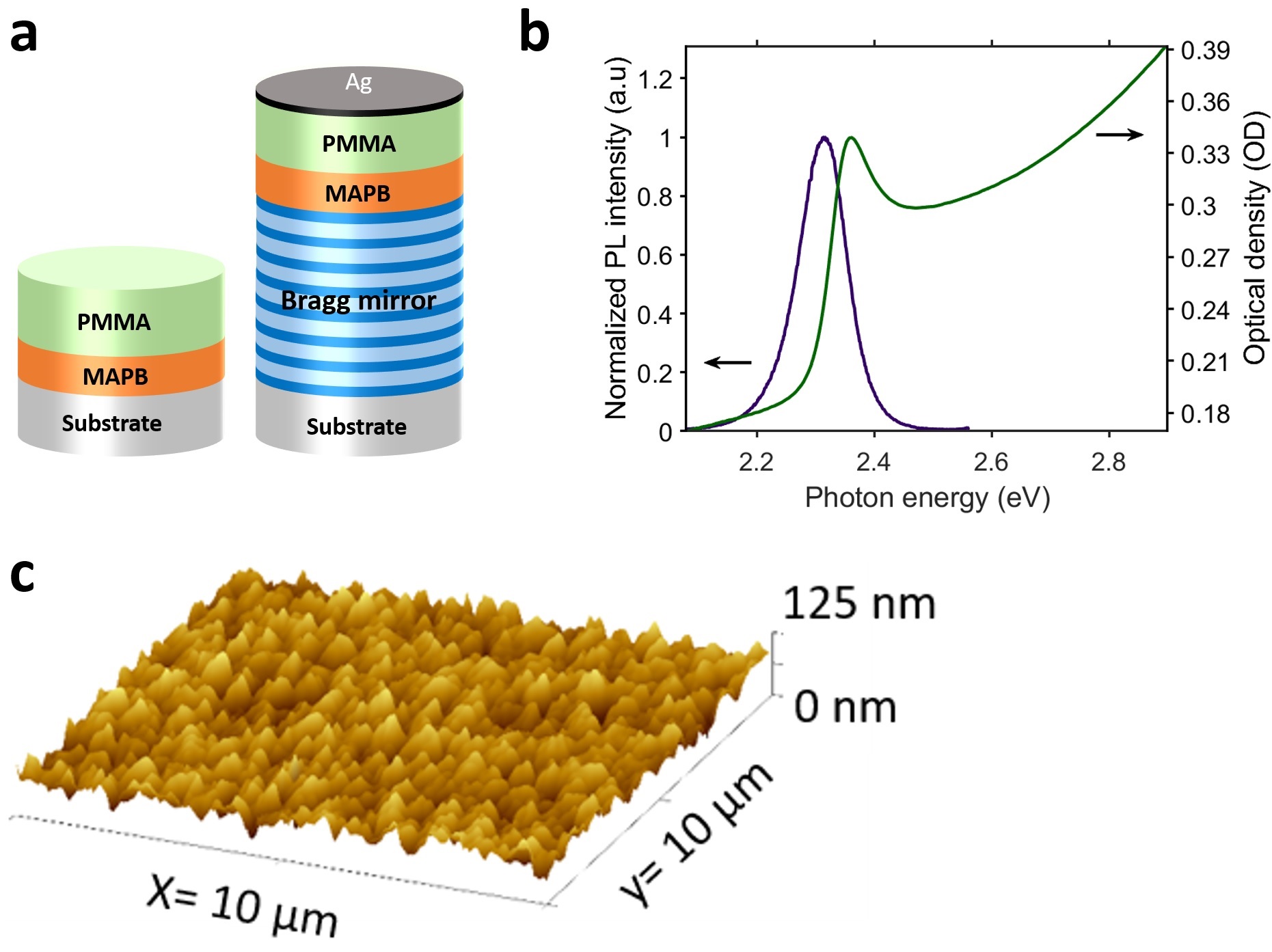
Two samples, sketched in figure 1 a), have been studied in this work. The first sample is a 100 nm-thick thin film of the perovskite CH3NH3PbBr3, called hereafter MAPB, deposited on a quartz substrate by spin coating. A layer of around 350 nm of PMMA (Poly(methyl) methacrylate) has been later deposited by spin coating on the MAPB layer. The second sample is a 3 MAPB-based microcavity, with nm the MAPB emission wavelength. This microcavity is composed by a commercial Bragg mirror (Layertec, corp) on which have been deposited the same two layers of MAPB ( 100nm) and PMMA ( 350 nm) by spin coating and a layer of 30 nm of silver by evaporation. The two samples fabrication is further detailed in the section 1 of the supplementary. The figure 1 b) shows the absorption and photoluminescence spectra of a control thin film of MAPB. The absorption spectrum is composed by an excitonic resonance at around 2.35 eV and a band absorption continuum at higher energies. The PL is Stokes-shifted at an energy of 2.32 eV with a Full Width at Half Maximum (FWHM) of 96 meV. Figure 1 c) presents an AFM scan of a control layer of MAPB: it reveals a polycrystalline film with a roughness of about 15 nm (RMS(grain-wise)=14.29 nm) composed by grains of 500 nm to 1 m size. Photoluminescence (PL) spectroscopy and angle-resolved photoluminescence (ARPL) as a function of the pump power have been performed on both samples. More details on the optical set-ups are given in the methods section of this article.
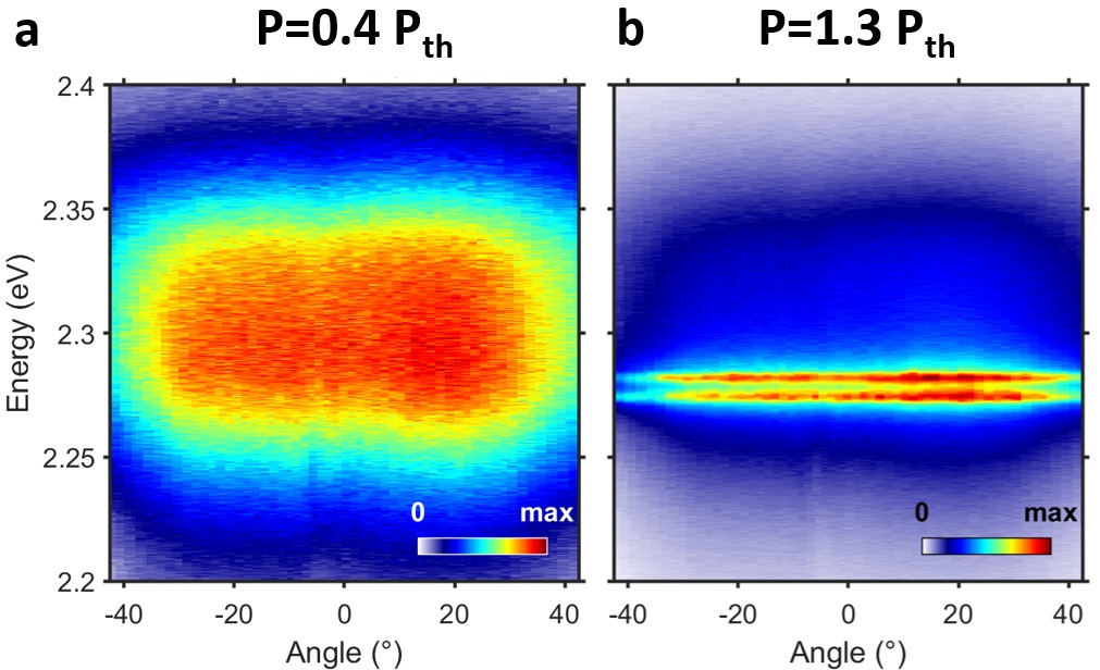
Due to the roughness of the MAPB layer, random lasing action is observed from the MAPB/PMMA sample. Such random lasing from perovskite polycrystalline thin films have already been demonstrated in the literature in MAPB thin layers Wang2019 ; Liu2019 . The PL spectroscopy demonstrating the random lasing is shown in the section 2 of the supplementary. Figures 2 a) and b) show the ARPL pseudo-colour maps below (at 0.4 ) and above (at 1.3 ) the random lasing threshold obtained on a position of the MAPB/PMMA sample. More data on this position such as the ARPL maps for other pumping powers are given in the section 3 of the supplementary. The ARPL map below the excitation threshold shows an angle-independent emission centred at 2.3 eV with an FWHM of 100 meV. Above the threshold, two random laser peaks can be clearly observed as two horizontal red lines at 2.275 eV and 2.283 eV while the broadband PL signal similar to the one below the threshold appears in dark blue. Such as the PL emission below the threshold, the random laser peaks emit in all directions from the sample’s surface as expected for a random lasing action in thin films Cao1999b . Indeed, the gain occurs within the plane of the MAPB film and the lasing emission is scattered out of the plane, resulting in an angle-independent emission from the surface of the MAPB/PMMA sample.
Considering the ease with which the strong coupling regime is observed in MAPB Bouteyre2019 ; Zhang2017 ; Shang2018a , the question of the photonic or polaritonic nature of the lasing can be reasonably raised here as it was raised by Niyuki et al. from a resonance-controlled ZnO random laser Niyuki2017 . Especially, the blueshift of the MAPB/PMMA lasing peaks (of around 1-2 meV between 1.1 and 1.8 , see section 2 of the Supplementary) could be in favour of a polaritonic lasing. However, the blueshift could just be explained by thermal effects as MAPB shows blueshift with temperature increase (of around 24 meV between 300K and 370K) Wright2016 . Nevertheless, to distinguish between the photonic and polaritonic nature of the lasing is hard and not within our reach in this paper. Indeed, the only way to demonstrate without ambiguity the existence of the polariton is to measure the mode dispersion from the random lasing emission and it is impossible in practice here due to the multiple light scattering.
Let us now focus on the 3/2 MAPB-based microcavity. In our previous study Bouteyre2019 , the strong coupling between the perovskite’s exciton and the microcavity photonic mode has been demonstrated on a similar microcavity and cavity polaritons have been observed experimentally (more details on the theory of the cavity polaritons are given in the methods section). In particular, we have shown that, due to the overall lateral roughness of the MAPB and PMMA layers, the cavity detuning, , with the cavity mode energy at normal incidence and the exciton energy, can be tuned by probing different lateral positions. This was due to the overall lateral roughness of the MAPB and PMMA layers. Only the lower cavity polariton dispersion can be observed in the ARPL maps of our previous study Bouteyre2019 . We will then only consider the lower cavity polariton whose eingenvalue is given by equation 1 :
| (1) |
where is the cavity dispersion, is the cavity effective refractive index, and are the linewidths of the photonic mode and the exciton, and V is the coupling strength. The real part of corresponds to the lower cavity polariton energy dispersion, , and the imaginary part to the lower cavity polariton linewidth, . From the study, the values of , , , and V were found to be 1.75, 2.355 eV, 25 meV, 90 meV and 48 meV respectively.
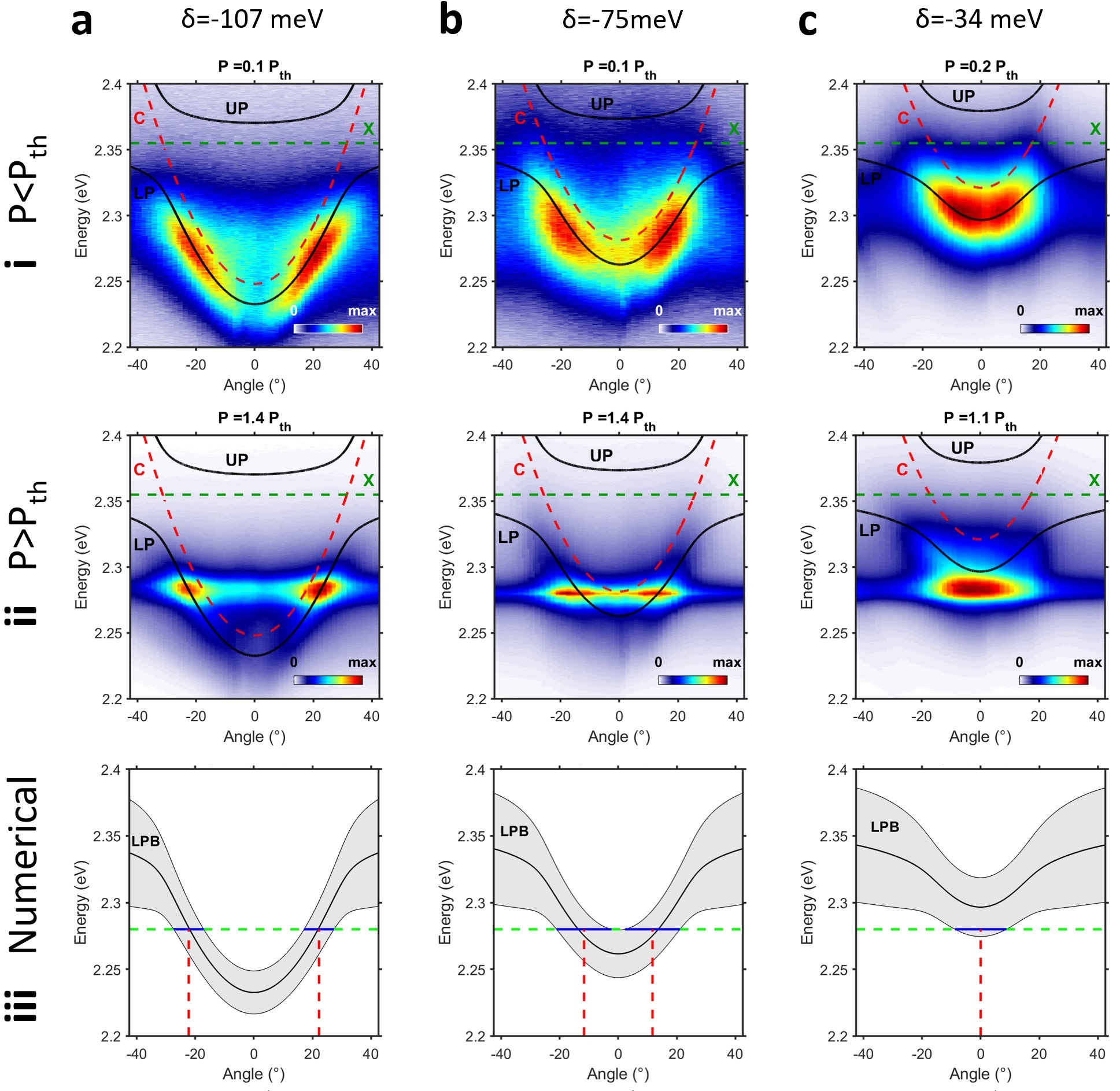
The figures 3 a), b) and c) show the ARPL pseudo-colour maps below (in the row (i)) and above (in the row (ii)) the lasing threshold of three different positions on the microcavity. Additional data are shown in the section 3 of the supplementary for each of these positions, including the map-integrated PL intensity as a function of the pump power demonstrating the lasing action of these positions. The dispersions corresponding to the three positions below the threshold (at 0.1, 0.1 and 0.2 ) are fitted with the lower cavity polariton dispersion, with the detuning, , as the only free parameter and the other parameters fixed at the values found in our previous study Bouteyre2019 . More details on the fitting method is presented in the section 4 of the supplementary. The detunings obtained for the three different positions are =-120 meV (=2.235 eV), =-85 meV (=2.27 eV) and =-35 meV (=2.22 eV) respectively. A good agreement is met between the lower cavity polariton dispersions and the dispersions of the ARPL maps confirming the strong coupling regime in this microcavity. The corresponding upper cavity polaritons dispersions, cavity mode dispersions and the exciton energy are also plotted on top of all the ARPL maps (see the methods section).
In the three ARPL maps above the threshold (at 1.4, 1.4 and 1.1 ) in the row (ii) of figures 3 a), b) and c), laser peaks appear in red while the lower cavity polariton emissions, similar to the ones below the threshold, appear in cyan and dark blue. To obtain the lasing peaks energies, angles and divergences, vertical and horizontal slices of the ARPL maps are respectively taken at given angles and energies (see the section 5 of the supplementary). For the first position corresponding to the largest detuning in figure 3 a), two laser peaks appear in dark red at 2.282 eV and 2.286 eV at the angles of 22.4∘ with a divergence of 12.5∘. For the second position probed on the microcavity (figure 3 b)), one laser peak in red emerges at 2.28 eV at angles around 15.8∘ with a divergence of 12.3∘. For these two cases, the angles at which the lasing peaks lie correspond to the intersection between the lower cavity polariton dispersion and the energy of lasing emission. For the third position probed on the microcavity (figure 3 c)), two peaks emerge at 2.282 eV and 2.286 eV in dark red. However, unlike the first two positions, the emission occurs at 0∘ with a divergence around 29.7∘. Moreover, the positions of the laser peaks lie under the theoretical lower cavity polariton dispersion.
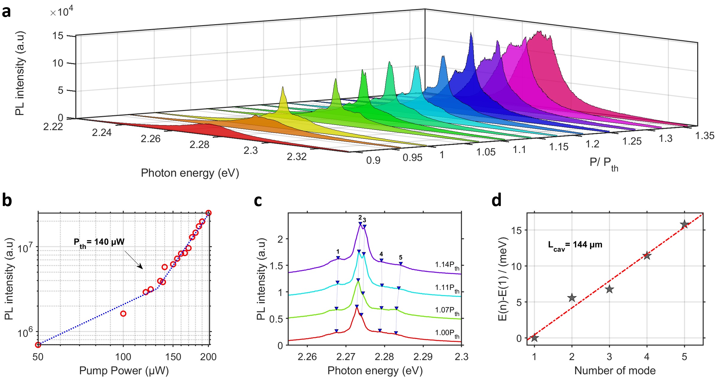
Figure 4 a) shows the photoluminescence spectra as a function of the pump power varying from 0.9 to 1.35 . The photoluminescence spectrum below the threshold is coupled to the microcavity mode, which leads to a spectrum shifted to 2.272 eV with an FWHM of 53 meV. When the pump power exceeds the threshold, laser peaks appear on top of the broadband PL with a dominant peak at 2.273 eV with an FWHM of 3 meV. Such as for the PL spectroscopy of the MAPB/PMMA sample (see section 2 of the supplementary), when the pump power further increases, other peaks occur at different energies, and the overall lasing spectrum is broadened as the modes begin to overlap. The log-log integrated PL as a function of the pumping power of figure 4 b) exhibits a threshold of 140 W. Note that the threshold is around two hundred times higher than the MAPB/PMMA sample threshold of 0.65 W (see section 2 of the supplementary). This is due to the high absorption of the silver mirror at 405 nm.
One could wonder if the microcavity lasing is the case of a polaritonic lasing which is the condensation of the cavity polaritons. A slight blueshift of the lasing modes, of about 1 meV between 1 and 1.15 , can be observed in figure 4 c) (showing four lasing spectra of figure 4 a) with a vertical offset for better readability) with the pumping power increasing, but as already discussed previously, can be due to the perovskite thermal effects. A first strong argument to rule out the condensation of cavity polaritons is the fact that an emission at lower energies than the theoretical cavity polaritonic dispersion is seen in figure 3 c) : this observation can not be explained by the cavity polaritonic lasing. However, in the case of the two positions corresponding to large detunings in figures 3 a), and b), the lasing emission at large angles could suggest a propagation of a polariton condensate, having the consequence that the polariton condensate can be observed at non-zero in-plane wavevectors. The polariton condensate propagation was recently observed with perovskites in a microcavity containing microwires of \chCsPbBr_3 Su2018 . This phenomenon is due to the polariton interactions with the excitonic reservoir, which ejects the polariton condensate radially from the center of the pump spot and provide the condensate with kinetic energy Wouters2008 . The phenomenon only takes place when the pump spot size is smaller than the polariton condensate propagation length. For larger spots, the polariton condensate lie at =0. For our system, the estimated propagation length of the polariton condensate is around 500 nm (see calculation in Methods). In our experiment, the pump laser beam was focused by a 0.9 NA objective for the first position in figure 3 a) and by a 5 cm lens for the positions in figures 3 b) and c). Thus, we observe that lasing emission occurs at large angles whether the microcavity is pumped with a spot whose radius is smaller or larger than 500 nm, which is a second strong argument to discredit the hypothesis of a propagation of the polariton condensate. As a conclusion, two arguments lead us to rule out the polaritonic lasing.
One could also wonder whether the lasing from the microcavity is just simply the case of a photonic laser from a VCSEL. In this case, only one lasing mode would have been expected in the range of photon energy of interest as the length of the microcavity is around 3 times the half of the MAPB emission wavelength (3/2). However, several modes, even though one mode dominates the others, have been observed in figure 4. The PL spectra on another position of the microcavity (see the section 6 of the supplementary) exhibit also, and more clearly, several modes which confirms the multimodal behavior of the microcavity lasing. This multimodal aspect allows us then to rule out the photonic lasing from the possible types of lasing.
On the other hand, we note that the lasing peaks seen in figure 3 and 4 occur at the same range of energy, between 2.26 eV and 2.29 eV, than the MAPB/PMMA sample (See section 2 of the supplementary). Indeed, for a random lasing action, the gain medium properties define the energy region of the lasing emission. Finally, the study in figure 4 d) of the free spectral range in energy, with an integer, of the lasing spectra in figure 4 c) gives a characteristic pseudo-cavity length (i.e. the length of the closed loops formed by the multiple scattering) of around 144 m (see more details in the methods section), which is similar to the one of 100 m found for the MAPB/PMMA sample (See section 2 of the supplementary). A value of the same order of magnitude (of around 215 m) has been found for another position of the microcavity in the section 6 of the supplementary. All these arguments are then in favor of the random lasing within the MAPB layer of the microcavity filtered directionally by the lower cavity polariton resonance. As a matter of fact, we think that in ref Lai2016 , the authors have observed such a filtering on the p-band lasing in a strong coupled ZnO microcavity.
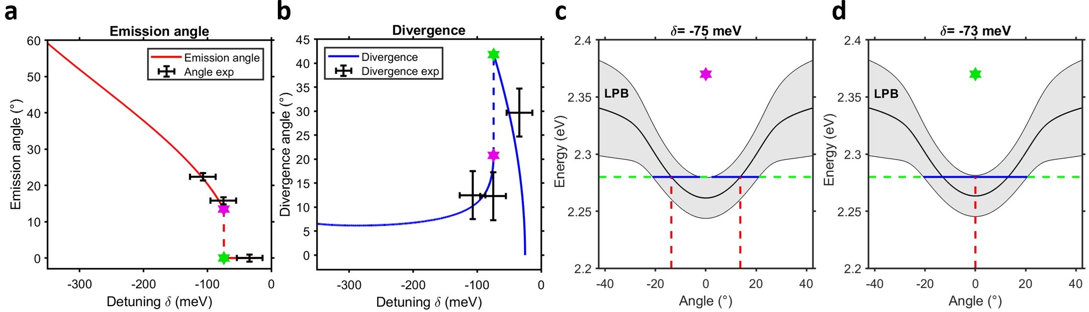
To further investigate the coupling of the random lasing with the lower cavity polariton resonance, the expected lasing angle and divergence as a function of the detuning is determined using the equation 1 and the parameters found from the fit of the dispersions. The energy of the random lasing emission is considered here to be 2.28 eV. Although the angle of emission can be easily derived in the case of the weak coupling, i.e. V=0 meV, the analytical solution is not trivial in the case of the strong coupling. A numerical approach illustrated by the figures in the row (iii) of figure 3 has been then chosen. The lower cavity polariton dispersions are plotted for a given detuning by taking into account the lower cavity polariton linewidths, , and are represented by the gray shaded areas. The center of the dispersions, , are plotted as black solid lines. The intersections between the lasing emission energies (green dashed lines) and the cavity polariton dispersions (gray shaded areas), give then the expected lasing angles and divergences.
For large negative detunings, lower than -74 meV, the intersection between the lasing emission energy and the cavity polariton dispersion gives rise to two distinct lobes of lasing emission. The two lobes at negative and positive angles are symmetric with respect to the normal direction. In this case, the two angles of emission (red dashed line) are given by the two intersections between the lasing emission energy (green dashed line) and the center of the cavity polariton dispersion (black solid line). The width in angle of the intersections between the lasing emission energy and the total lower cavity polariton dispersion (gray shaded area) determines the dispersion angle (solid blue line). The ARPL maps obtained from the first two positions of the microcavity in figure 3 a) and b) in the lines (i) and (ii) as well as their theoretical dispersions in the line (iii) clearly demonstrate the cavity polaritonic filtering. When the detunings are above -74 meV, the intersection between the lasing emission energy and the lower cavity polariton dispersion generates only one lasing lobe centered at 0∘ with a large divergence. This is due to the two lobes merging into one due to their increased widths. This is the case of the emission of the third position probed on the microcavity in figure 3 c). Figures 5 c) and d) illustrating the numerical methods at the detunings =-75 and -73 meV shows the transition between the two cases of coupling detailed previously. Figure 5 a) shows the numerical results for the expected emission angle (red line) and figure 5 b) the divergence (blue line) both along with the experimental results (black cross). Only the lasing lobes at positive angles are plotted in figure 5. The agreement between the experimental and numerical lasing angles and divergences validate the directional filtering of the lasing emission by the lower cavity polariton resonance.
In conclusion, we have shown that the directionality of the random lasing in a \chCH_3NH_3PbBr_3 polycrystalline thin layer can be controlled by the lower cavity polariton resonance of a 3/2 microcavity in the strong coupling regime. In particular, we highlight here that we have obtained a directional random lasing assisted by the cavity polaritons at angles as large as ± 20∘ with divergence angles of around 15∘ and that the angle of emission can be controlled in such a system by changing the detuning, that is to say the thickness, of the microcavity. To decrease the emission divergence, one has to decrease the lower cavity polariton linewidth by improving the microcavity quality factor (see section 7 of the supplementary). Directing random laser emission through a photonic structure acting as an external knob is expected to open bright perspectives in the area of hybrid perovskites optoelectronics. Beyond vertical Fabry-Perot cavities, emission could be filtered by photonic crystals or dispersion-engineered metasurfaces, bringing additional degrees of freedom, together with a high compactness Nguyen2018 . Used as external wavelength and direction filters rather than laser cavities, such nanophotonic structures can be technologically tolerant, and compatible with electrical injection.
Methods
PL and ARPL as a function of the excitation power Photoluminescence (PL) spectroscopy and angle-resolved photoluminescence (ARPL) as a function of the excitation power have been performed on the two samples with a femtosecond pulsed laser emitting at 405 nm (150 fs, 1 kHz rep.rate). The ARPL optical set-up is shown in the supplementary of our previous article Bouteyre2019 and sketches of the different excitation configurations are shown in the section 8 of the supplementary.
For the MAPB/PMMA sample, the ARPL maps of the figure 2 and the PL spectroscopy in the section 2 of the supplementary were obtained by using a first configuration : a 0.9 NA objective was used for focusing the pump laser and collecting the PL from the PMMA side. The spectrometer used was the spectrometer Princeton Instruments SP2150 ( nm, meV for = 2.28 eV). For the microcavity, the ARPL maps of the position presented in figure 3 a) have been obtained with the same configuration. In this case, the focus and collection were done on the silver side.
A second configuration, with the same spectrometer was used for the ARPL maps on figure 3 b) and c): the focus was made by a 5-cm lens through the Bragg mirror and the collection with the 0.9 NA objective from the silver side.
In the case of the PL spectroscopy of the microcavity, in figure 4 and in the section 5 of the supplementary, a third configuration was opted: a 0.6 NA objective was used for focusing the pump laser and collecting the PL from the silver side. In this case, the spectrometer was the Princeton Instruments SP2500 ( nm, meV for = 2.28 eV).
Theory of the strong coupling regime The strong coupling between an exciton and the photonic mode of a microcavity can be simplified into a two-level model. The system Hamiltonian in the two dimensional basis, (,), can be then written as such :
where V is the coupling strength, and are the excitonic and photonic linewidths. The photonic mode dispersion is given by :
with the microcavity effective refractive index and the detuning which is the difference between the excitonic energy, , and the photonic mode energy at normal incidence .
Solving the system’s Schrödinger equation gives rise to two new quasi-particles : the lower and upper cavity polaritons, which are the coherent superposition of the photonic and excitonic states. The eingenvalues of the lower and upper cavity polaritons, and are given by:
where the real parts of correspond to the cavity polariton energy dispersions, and , and the imaginary part to the cavity polariton linewidths, and .
Estimation of the polariton propagation length
The polariton propagation length is given by , where is the polariton lifetime and is the polariton velocity. The polariton lifetime can be approximated to be close to the photonic mode lifetime , with the reduced Planck constant, the quality factor, and the photonic mode energy at normal incidence. In our case Bouteyre2019 , which gives an estimation of the polariton lifetime fs. In the case of a propagation of a polariton condensate, the polariton velocity is given by , where is the lower polariton effective mass, and is the wavenumber of the propagated polariton condensate Wouters2008 . The polariton effective mass, , is related to the curvature of the LPB branch at and can be obtained with , where C is the coefficient of a parabola () fitting the LPB at low . Using the parameters found to fit the LPB dispersion in figure 3 a) (figure 3 b)), the LPB effective mass is found to be 8.3(8.9) . The wavenumber of the propagated polariton condensate is related to the emission angle, , and photon energy, , of the polariton condensate as . In our case, and correspond to the lasing emission angle and energy: eV and = 22.4∘ and 15.8∘ for the figures 3 a) and b), respectively. The polariton propagation lengths of 470 nm and 309 nm are found respectively for the figures 3 a) and b).
Study of the free spectral range of the lasing spectra to determine the characteristic size of the MAPB pseudo-cavities
The method used to obtain the characteristic size of the MAPB pseudo-cavities is the following. The free spectral range in energy, with m an integer, of the lasing spectra is studied by collecting the average energies of the modes shown in figure 4 c). The difference in energy between the modes and the mode is plotted against the modes numbers and is fitted with a linear function. The cavity length is retrieved from , where is the MAPB refractive index, is the light velocity and is the slope of the linear function.
Funding Information
This work is supported by Agence Nationale de la Recherche (ANR) within the projects POPEYE (ANR-17-CE24-0020) and EMIPERO (ANR-18-CE24-0016). The work of P.Bouteyre is supported by the Direction Générale de l′Armement (DGA).
Acknowledgments
We thank Rasta Ghasemi, from Institut d′Alembert de l′École Normale Supérieure de Paris-Saclay, for her technical support in the evaporation of the metallic mirrors.
Supplemental Documents
The following files are available free of charge.
-
•
Additional information (PDF) on the fabrication of the MAPB/PMMA sample and the 3 MAPB-based microcavity, the PL spectroscopy carried on the MAPB/PMMA sample to demonstrate the random lasing, additional data on the ARPL of the MAPB/PMMA sample and the three positions of the 3/2 MAPB based-microcavity, the fitting method of the lower polariton dispersion curves of the three positions in figure 3, slices taken at given angles and at given energies of the ARPL maps in figure 3, PL spectra as a function of the pump power on another position of the microcavity, a study of the impact of the quality factor on the emission divergence and the sketch of the excitation configurations of the MAPB/PMMA sample and the 3 MAPB-based microcavity.
References
- (1) D. S. Wiersma, “The physics and applications of random lasers,” Nature Physics, vol. 4, p. 359, May 2008.
- (2) H. Cao, “Review on latest developments in random lasers with coherent feedback,” Journal of Physics A: Mathematical and General, vol. 38, pp. 10497–10535, nov 2005.
- (3) V. Letokhov, “Stimulated emission of an ensemble of scattering particles with negative absorption,” ZhETF Pisma Redaktsiiu, vol. 5, p. 262, 1967.
- (4) D. S. Wiersma and A. Lagendijk, “Light diffusion with gain and random lasers,” Phys. Rev. E, vol. 54, pp. 4256–4265, Oct 1996.
- (5) H. Cao, Y. G. Zhao, S. T. Ho, E. W. Seelig, Q. H. Wang, and R. P. H. Chang, “Random laser action in semiconductor powder,” Phys. Rev. Lett., vol. 82, pp. 2278–2281, Mar 1999.
- (6) H. Cao, Y. G. Zhao, H. C. Ong, and R. P. H. Chang, “Far-field characteristics of random lasers,” Phys. Rev. B, vol. 59, pp. 15107–15111, Jun 1999.
- (7) C. Weisbuch, M. Nishioka, A. Ishikawa, and Y. Arakawa, “Observation of the coupled exciton-photon mode splitting in a semiconductor quantum microcavity,” Phys. Rev. Lett., vol. 69, pp. 3314–3317, Dec 1992.
- (8) G. Panzarini, L. C. Andreani, A. Armitage, D. Baxter, M. S. Skolnick, V. N. Astratov, J. S. Roberts, A. V. Kavokin, M. R. Vladimirova, and M. A. Kaliteevski, “Cavity-polariton dispersion and polarization splitting in single and coupled semiconductor microcavities,” Physics of the Solid State, vol. 41, pp. 1223–1238, Aug 1999.
- (9) D. Sanvitto and S. Kéna-Cohen, “The road towards polaritonic devices,” Nature Materials, vol. 15, p. 1061, July 2016.
- (10) H. Cao, Y. G. Zhao, H. C. Ong, S. T. Ho, J. Y. Dai, J. Y. Wu, and R. P. H. Chang, “Ultraviolet lasing in resonators formed by scattering in semiconductor polycrystalline films,” Applied Physics Letters, vol. 73, pp. 3656–3658, dec 1998.
- (11) T. Hisch, M. Liertzer, D. Pogany, F. Mintert, and S. Rotter, “Pump-controlled directional light emission from random lasers,” Phys. Rev. Lett., vol. 111, p. 023902, Jul 2013.
- (12) Q. Song, L. Liu, and L. Xu, “Directional random-laser emission from bragg gratings with irregular perturbation,” Optics Letters, vol. 34, p. 344, jan 2009.
- (13) S. K. Turitsyn, S. A. Babin, A. E. El-Taher, P. Harper, D. V. Churkin, S. I. Kablukov, J. D. Ania-Castañón, V. Karalekas, and E. V. Podivilov, “Random distributed feedback fibre laser,” Nature Photonics, vol. 4, pp. 231–235, feb 2010.
- (14) X. T. Long, Q. F. Dai, H. H. Fan, Z. C. Wei, M. M. Wu, and H. Z. Wang, “Dominant mode in closed photonic crystal microcavity filled with high scattering irregular gain medium,” Applied Physics Letters, vol. 89, p. 251105, dec 2006.
- (15) Q. Song, L. Liu, S. Xiao, X. Zhou, W. Wang, and L. Xu, “Unidirectional high intensity narrow-linewidth lasing from a planar random microcavity laser,” Phys. Rev. Lett., vol. 96, p. 033902, Jan 2006.
- (16) Q. Song, S. Xiao, X. Zhou, L. Liu, L. Xu, Y. Wu, and Z. Wang, “Liquid-crystal-based tunable high-q directional random laser from a planar random microcavity,” Opt. Lett., vol. 32, pp. 373–375, Feb 2007.
- (17) Q. Song, L. Liu, L. Xu, Y. Wu, and Z. Wang, “Electrical tunable random laser emission from a liquid-crystal infiltrated disordered planar microcavity,” Optics Letters, vol. 34, p. 298, jan 2009.
- (18) P. N. Ni, C. X. Shan, S. P. Wang, Y. J. Lu, B. H. Li, and D. Z. Shen, “Fabry-perot resonance enhanced electrically pumped random lasing from ZnO films,” Applied Physics Letters, vol. 107, p. 231108, dec 2015.
- (19) S. Schönhuber, M. Brandstetter, T. Hisch, C. Deutsch, M. Krall, H. Detz, A. M. Andrews, G. Strasser, S. Rotter, and K. Unterrainer, “Random lasers for broadband directional emission,” Optica, vol. 3, pp. 1035–1038, Oct 2016.
- (20) M. Lee, S. Callard, C. Seassal, and H. Jeon, “Taming of random lasers,” Nature Photonics, vol. 13, pp. 445–448, July 2019.
- (21) H. Zhu, Y. Fu, F. Meng, X. Wu, Z. Gong, Q. Ding, M. V. Gustafsson, M. T. Trinh, S. Jin, and X.-Y. Zhu, “Lead halide perovskite nanowire lasers with low lasing thresholds and high quality factors,” Nature Materials, vol. 14, p. 636, Apr. 2015.
- (22) Q. Zhang, S. T. Ha, X. Liu, T. C. Sum, and Q. Xiong, “Room-temperature near-infrared high-q perovskite whispering-gallery planar nanolasers,” Nano Letters, vol. 14, no. 10, pp. 5995–6001, 2014.
- (23) M. Saliba, S. M. Wood, J. B. Patel, P. K. Nayak, J. Huang, J. A. Alexander-Webber, B. Wenger, S. D. Stranks, M. T. Hörantner, J. T.-W. Wang, et al., “Structured organic–inorganic perovskite toward a distributed feedback laser,” Advanced Materials, vol. 28, no. 5, pp. 923–929, 2016.
- (24) S. Chen, K. Roh, J. Lee, W. K. Chong, Y. Lu, N. Mathews, T. C. Sum, and A. Nurmikko, “A photonic crystal laser from solution based organo-lead iodide perovskite thin films,” Acs Nano, vol. 10, no. 4, pp. 3959–3967, 2016.
- (25) F. Deschler, M. Price, S. Pathak, L. E. Klintberg, D.-D. Jarausch, R. Higler, S. Hüttner, T. Leijtens, S. D. Stranks, H. J. Snaith, M. Atatüre, R. T. Phillips, and R. H. Friend, “High photoluminescence efficiency and optically pumped lasing in solution-processed mixed halide perovskite semiconductors,” The Journal of Physical Chemistry Letters, vol. 5, no. 8, pp. 1421–1426, 2014.
- (26) Y.-H. Kim, H. Cho, J. H. Heo, T.-S. Kim, N. Myoung, C.-L. Lee, S. H. Im, and T.-W. Lee, “Multicolored organic/inorganic hybrid perovskite light-emitting diodes,” Advanced Materials, vol. 27, no. 7, pp. 1248–1254, 2015.
- (27) T. S. Kao, Y.-H. Chou, C.-H. Chou, F.-C. Chen, and T.-C. Lu, “Lasing behaviors upon phase transition in solution-processed perovskite thin films,” Applied Physics Letters, vol. 105, no. 23, p. 231108, 2014.
- (28) R. Dhanker, A. Brigeman, A. Larsen, R. Stewart, J. Asbury, and N. Giebink, “Random lasing in organo-lead halide perovskite microcrystal networks,” Applied Physics Letters, vol. 105, no. 15, p. 151112, 2014.
- (29) Z.-F. Shi, X.-G. Sun, D. Wu, T.-T. Xu, Y.-T. Tian, Y.-T. Zhang, X.-J. Li, and G.-T. Du, “Near-infrared random lasing realized in a perovskite CH3nh3pbi3 thin film,” Journal of Materials Chemistry C, vol. 4, no. 36, pp. 8373–8379, 2016.
- (30) T. S. Kao, Y.-H. Chou, K.-B. Hong, J.-F. Huang, C.-H. Chou, H.-C. Kuo, F.-C. Chen, and T.-C. Lu, “Controllable lasing performance in solution-processed organic–inorganic hybrid perovskites,” Nanoscale, vol. 8, no. 43, pp. 18483–18488, 2016.
- (31) A. Safdar, Y. Wang, and T. F. Krauss, “Random lasing in uniform perovskite thin films,” Optics Express, vol. 26, no. 2, pp. A75–A84, 2018.
- (32) S. Yakunin, L. Protesescu, F. Krieg, M. I. Bodnarchuk, G. Nedelcu, M. Humer, G. De Luca, M. Fiebig, W. Heiss, and M. V. Kovalenko, “Low-threshold amplified spontaneous emission and lasing from colloidal nanocrystals of caesium lead halide perovskites,” Nature communications, vol. 6, p. 8056, 2015.
- (33) X. Li, Y. Wang, H. Sun, and H. Zeng, “Amino-mediated anchoring perovskite quantum dots for stable and low-threshold random lasing,” Advanced Materials, vol. 29, p. 1701185, jul 2017.
- (34) C. Li, Z. Zang, C. Han, Z. Hu, X. Tang, J. Du, Y. Leng, and K. Sun, “Highly compact CsPbBr 3 perovskite thin films decorated by ZnO nanoparticles for enhanced random lasing,” Nano Energy, vol. 40, pp. 195–202, oct 2017.
- (35) S. Yuan, D. Chen, X. Li, J. Zhong, and X. Xu, “In situ crystallization synthesis of CsPbBr3 perovskite quantum dot-embedded glasses with improved stability for solid-state lighting and random upconverted lasing,” ACS Applied Materials & Interfaces, vol. 10, pp. 18918–18926, may 2018.
- (36) L. Xu, Y. Meng, C. Xu, and P. Chen, “Room temperature two-photon-pumped random lasers in FAPbBr3/polyethylene oxide (PEO) composite perovskite thin film,” RSC Advances, vol. 8, no. 64, pp. 36910–36914, 2018.
- (37) S. Liu, W. Sun, J. Li, Z. Gu, K. Wang, S. Xiao, and Q. Song, “Random lasing actions in self-assembled perovskite nanoparticles,” Optical Engineering, vol. 55, p. 057102, may 2016.
- (38) P. K. Roy, G. Haider, H.-I. Lin, Y.-M. Liao, C.-H. Lu, K.-H. Chen, L.-C. Chen, W.-H. Shih, C.-T. Liang, and Y.-F. Chen, “Multicolor ultralow-threshold random laser assisted by vertical-graphene network,” Advanced Optical Materials, vol. 6, p. 1800382, may 2018.
- (39) G. Weng, J. Xue, J. Tian, X. Hu, X. Bao, H. Lin, S. Chen, Z. Zhu, and J. Chu, “Picosecond random lasing based on three-photon absorption in organometallic halide CH3nh3pbbr3 perovskite thin films,” ACS Photonics, vol. 5, pp. 2951–2959, may 2018.
- (40) T. Fan, J. Lü, Y. Chen, W. Yuan, and Y. Huang, “Random lasing in cesium lead bromine perovskite quantum dots film,” Journal of Materials Science: Materials in Electronics, vol. 30, pp. 1084–1088, Jan 2019.
- (41) A. Mikosch, S. Ciftci, G. Tainter, R. Shivanna, B. Haehnle, F. Deschler, and A. J. C. Kuehne, “Laser emission from self-assembled colloidal crystals of conjugated polymer particles in a metal-halide perovskite matrix,” Chemistry of Materials, vol. 31, no. 7, pp. 2590–2596, 2019.
- (42) G. Weng, J. Tian, S. Chen, J. Xue, J. Yan, X. Hu, S. Chen, Z. Zhu, and J. Chu, “Giant reduction of the random lasing threshold in ch3nh3pbbr3 perovskite thin films by using a patterned sapphire substrate,” Nanoscale, pp. –, 2019.
- (43) Y.-C. Wang, H. Li, Y.-H. Hong, K.-B. Hong, F.-C. Chen, C.-H. Hsu, R.-K. Lee, C. Conti, T. S. Kao, and T.-C. Lu, “Flexible organometal–halide perovskite lasers for speckle reduction in imaging projection,” ACS Nano, vol. 13, no. 5, pp. 5421–5429, 2019. PMID: 31009199.
- (44) X. Tang, Y. Bian, Z. Liu, J. Du, M. Li, Z. Hu, J. Yang, W. Chen, and L. Sun, “Room-temperature up-conversion random lasing from cspbbr3 quantum dots with tio2 nanotubes,” Opt. Lett., vol. 44, pp. 4706–4709, Oct 2019.
- (45) Y. Liu, W. Yang, S. Xiao, N. Zhang, Y. Fan, G. Qu, and Q. Song, “Surface-emitting perovskite random lasers for speckle-free imaging,” ACS Nano, vol. 13, no. 9, pp. 10653–10661, 2019. PMID: 31430124.
- (46) A. Brehier, R. Parashkov, J. S. Lauret, and E. Deleporte, “Strong exciton-photon coupling in a microcavity containing layered perovskite semiconductors,” Applied Physics Letters, vol. 89, no. 17, p. 171110, 2006.
- (47) G. Lanty, J. S. Lauret, E. Deleporte, S. Bouchoule, and X. Lafosse, “Uv polaritonic emission from a perovskite-based microcavity,” Applied Physics Letters, vol. 93, no. 8, p. 081101, 2008.
- (48) R. Su, C. Diederichs, J. Wang, T. C. H. Liew, J. Zhao, S. Liu, W. Xu, Z. Chen, and Q. Xiong, “Room-temperature polariton lasing in all-inorganic perovskite nanoplatelets,” Nano Letters, vol. 17, no. 6, pp. 3982–3988, 2017.
- (49) R. Su, J. Wang, J. Zhao, J. Xing, W. Zhao, C. Diederichs, T. C. H. Liew, and Q. Xiong, “Room temperature long-range coherent exciton polariton condensate flow in lead halide perovskites,” Science Advances, vol. 4, no. 10, p. eaau0244, 2018.
- (50) P. Bouteyre, H. S. Nguyen, J.-S. Lauret, G. Trippé-Allard, G. Delport, F. Lédée, H. Diab, A. Belarouci, C. Seassal, D. Garrot, F. Bretenaker, and E. Deleporte, “Room-temperature cavity polaritons with 3d hybrid perovskite: Toward large-surface polaritonic devices,” ACS Photonics, vol. 6, no. 7, pp. 1804–1811, 2019.
- (51) S. Zhang, Q. Shang, W. Du, J. Shi, Z. Wu, Y. Mi, J. Chen, F. Liu, Y. Li, M. Liu, Q. Zhang, and X. Liu, “Strong exciton-photon coupling in hybrid inorganic-organic perovskite micro/nanowires,” Advanced Optical Materials, vol. 6, no. 2, p. 1701032, 2018.
- (52) Q. Shang, S. Zhang, Z. Liu, J. Chen, P. Yang, C. Li, W. Li, Y. Zhang, Q. Xiong, X. Liu, and Q. Zhang, “Surface plasmon enhanced strong exciton-photon coupling in hybrid inorganic-organic perovskite nanowires,” Nano Letters, vol. 18, no. 6, pp. 3335–3343, 2018.
- (53) R. Niyuki, H. Fujiwara, T. Nakamura, Y. Ishikawa, N. Koshizaki, T. Tsuji, and K. Sasaki, “Double threshold behavior in a resonance-controlled zno random laser,” APL Photonics, vol. 2, no. 3, p. 036101, 2017.
- (54) A. D. Wright, C. Verdi, R. L. Milot, G. E. Eperon, M. A. Pérez-Osorio, H. J. Snaith, F. Giustino, M. B. Johnston, and L. M. Herz, “Electron-phonon coupling in hybrid lead halide perovskites,” Nature Communications, vol. 7, p. 11755, May 2016.
- (55) M. Wouters, I. Carusotto, and C. Ciuti, “Spatial and spectral shape of inhomogeneous nonequilibrium exciton-polariton condensates,” Phys. Rev. B, vol. 77, p. 115340, Mar 2008.
- (56) Y.-Y. Lai, Y.-H. Chou, Y.-P. Lan, T.-C. Lu, S.-C. Wang, and Y. Yamamoto, “Crossover from polariton lasing to exciton lasing in a strongly coupled zno microcavity,” Scientific Reports, vol. 6, p. 20581, Feb. 2016.
- (57) H. S. Nguyen, F. Dubois, T. Deschamps, S. Cueff, A. Pardon, J.-L. Leclercq, C. Seassal, X. Letartre, and P. Viktorovitch, “Symmetry breaking in photonic crystals: On-demand dispersion from flatband to dirac cones,” Phys. Rev. Lett., vol. 120, p. 066102, Feb 2018.