A Cryogenic Silicon Interferometer for Gravitational-wave Detection
Abstract
The detection of gravitational waves from compact binary mergers by LIGO has opened the era of gravitational wave astronomy, revealing a previously hidden side of the cosmos. To maximize the reach of the existing LIGO observatory facilities, we have designed a new instrument able to detect gravitational waves at distances 5 times further away than possible with Advanced LIGO, or at greater than 100 times the event rate. Observations with this new instrument will make possible dramatic steps toward understanding the physics of the nearby universe, as well as observing the universe out to cosmological distances by the detection of binary black hole coalescences. This article presents the instrument design and a quantitative analysis of the anticipated noise floor.
1 Introduction
The first detection of gravitational waves (GW) from the object GW150914 [1] by the Advanced LIGO (aLIGO) detectors inaugurated a new field of study: gravitational wave astronomy. The subsequent detection of a binary neutron star merger [2] has highlighted the possibilities of this new field.
GW detectors provide a probe of physics in a new regime. They offer the best information about the extremely warped spacetime around black holes, exotic nuclear matter in neutron stars, and, within the next decade, a unique probe of cosmology at high redshifts.
The current LIGO detectors will approach the thermodynamic and quantum mechanical limits of their designs within a few years. Over the next several years, aLIGO will undergo a modest upgrade, designated “A+”. The aim of this upgrade is chiefly to lower the quantum (shot) noise through the use of squeezed light, and also to reduce somewhat the thermal noise from the mirror coatings. This upgrade has the goal of enhancing the sensitivity by 50% [3].
In this article, we describe a more substantial upgrade, called “LIGO Voyager”, that will increase the range by a factor of 4 – 5 over aLIGO, and the event rate by approximately 100 times, to roughly one detection per hour. Such a dramatic change in the sensitivity should increase the detection rate of binary neutron star mergers to about 10 per day and the rate of binary black hole mergers to around 30 per day. This upgraded instrument would be able to detect binary black holes out to a redshift of 8.
The path to LIGO Voyager requires reducing several noise sources, including:
-
1.
quantum radiation pressure and shot noise,
-
2.
mirror thermal noise,
-
3.
mirror suspension thermal noise,
-
4.
Newtonian gravity noise
All of these noise sources are addressed by the LIGO Voyager design, with the goal of commissioning and observational runs within a decade.
1.1 Justification
The most significant design changes in LIGO Voyager versus Advanced LIGO can be traced to the need to reduce the quantum noise in tandem with the mirror thermal noise.
-
•
Quantum noise will be reduced by increasing the optical power stored in the arms. In Advanced LIGO, the stored power is limited by thermally induced wavefront distortion effects in the fused silica test masses. These effects will be alleviated by choosing a test mass material with a high thermal conductivity, such as silicon.
-
•
The test mass temperature will be lowered to 123 K, to mitigate thermo-elastic noise. This species of thermal noise is especially problematic in test masses that are good thermal conductors. Fortunately, in silicon at 123 K, the thermal expansion coefficient crosses zero, which eliminates thermo-elastic noise. (Other plausible material candidates, such as sapphire, require cooling to near 0 K to be free of this noise.)
-
•
The thermal noise of the mirror coating will be reduced by switching to low dissipation amorphous silicon based coatings, and by reducing the temperature. Achieving low optical absorption in the amorphous silicon coatings requires an increased laser wavelength.
1.2 Design overview
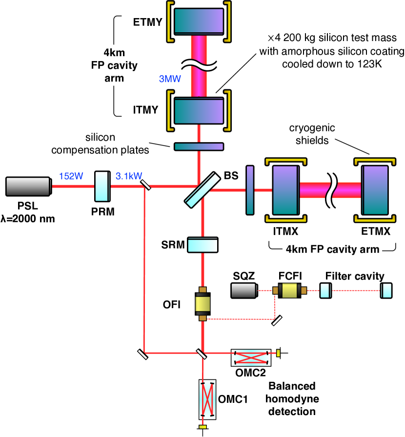
The LIGO Voyager design is illustrated in Figure 1, with critical parameters called out in Table 1. The dual-recycled, Fabry-Perot Michelson topology is similar to Advanced LIGO and A+, with the following additional upgrades. Optical coatings on the cryogenically-cooled (123 K) test masses will be made from amorphous silicon, with the lower coating mechanical loss and cryogenic operation reducing the coating thermal noise. The 200 kg test-masses will be made of crystalline silicon (rather than fused silica). The absorption spectrum of the test mass materials requires us to choose a longer wavelength laser. The longer wavelength will also significantly reduce optical scattering from the mirrors, lowering losses and allowing for higher finesse arm cavities. The quantum noise (shot noise and radiation pressure) will be reduced by a combination of frequency-dependent squeezing, heavier test masses, and higher stored power in the arms. Finally, the environmentally produced Newtonian gravitational noise [4] will be reduced using seismometer arrays combined with adaptive noise regression [5, 6].
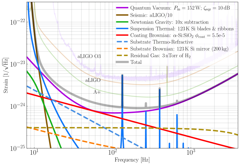
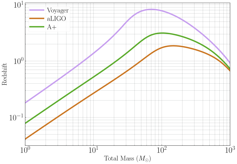
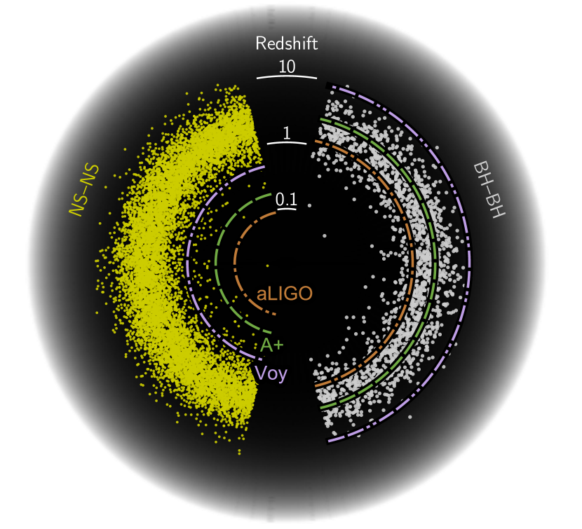
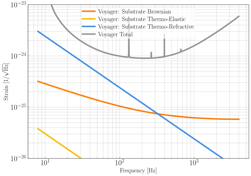
The LIGO Voyager noise budget and resulting design sensitivity are shown in Figure 2. Horizon distances for astrophysical sources are illustrated in Figure 3(a) and Figure 3(b), showing the improvement over the Advanced LIGO design.
Although most optical components will need to be changed to handle the new wavelength, we plan on reusing the Advanced LIGO hardware and infrastructure wherever possible (for example, the seismic isolation platforms, vacuum systems, electronics and infrastructure).
| Parameter | Nominal value |
|---|---|
| Laser wavelength | |
| Laser power incident on PRM | |
| Power in PRC | |
| Arm power | |
| Mirror substrate | silicon |
| Mirror radius | |
| Mirror thickness | |
| Beam radius on ITM/ETM111 intensity | / |
| ITM transmittance | |
| PRM transmittance | |
| SRM transmittance | |
| Mass per stage | 50/70// kg |
| Final stage temperature | 123 K |
| Final stage construction | silicon ribbon |
| Final stage length | |
| Newtonian noise suppression | |
| Injected squeeze factor | |
| Squeeze injection loss | |
| Squeeze filter cavity length | |
| Squeeze filter cavity loss222Round-trip loss; see section 5.2 |
1.3 Article overview
This article presents a detailed description of the LIGO Voyager design with the goals of (a) investigating the feasibility of all the required technology, largely illustrated in Figure 1, and highlighting those technological areas that require further research and (b) describing all the key noise contributions illustrated in the noise budget in Figure 2 (and thus determining the LIGO Voyager sensitivity).
The structure of the paper is as follows. In Section 2, we examine the feasibility of using large, cryogenically-cooled (123 K) silicon test masses and identify the substrate thermo-refractive noise, shown in the noise budget, as the limiting noise source associated with the test mass. Section 3 describes an amorphous-silicon based coating design that delivers the coating Brownian noise curve shown in the noise budget and also identifies coating absorption as a key obstacle that must be overcome. The numerous factors that enter into the choice of as the laser wavelength are described in detail in Section 4. Quantum noise as a limiting noise source and the feasibility of injecting 10 dB of frequency-dependent squeezed vacuum at 2000 nm are considered in Section 5. The suspension thermal noise (associated with the use of silicon blades and ribbons) is described in Section 6. This section also explores the practicality of manufacturing these silicon blades and ribbons. In Section 7, we review the development of mid-IR laser sources and find no significant impediment to producing a thulium- or holmium-based , low-noise, single-frequency, laser within the next 10 years. Section 8 explores configurations of LIGO Voyager that are optimized for high-frequency astrophysical sources, given the considerable tunability of the quantum noise curve and interferometer optical configuration. Finally, cryogenic considerations are discussed in Appendix A.
2 Test Masses
2.1 Material
We have chosen 123 K crystalline silicon as the test mass material for LIGO Voyager. Figure 4 shows the thermal noise strain curves from crystalline silicon test masses held at 123 K, where it can be seen that neither Brownian nor thermo-optic substrate noises should limit detector sensitivity. To justify this material and temperature choice, we compare its thermal noise performance with three other materials that are currently used or proposed for use in GW interferometers: fused silica [8, 9], sapphire [10], and 10 K silicon [11].
Thermal noise in a fused silica test mass is limited by Brownian motion, which is related to mechanical loss through the fluctuation-dissipation theorem [12, 13, 14]. In fused silica, the mechanical loss has a broad peak below room temperature. Thus its thermal noise does not benefit from cryogenic cooling [15]. Silicon has lower mechanical loss, and consequently lower Brownian noise than fused silica without any loss peaks at low temperatures [16].
Sapphire, like silicon, is free of cryogenic loss peaks. However, thermo-elastic noise is an important noise mechanism in these two crystalline materials, due to their high thermal conductivity. Thermodynamic fluctuations of heat inside the material are the source of this noise. The fluctuations are converted to mirror surface displacement through the coefficient of thermal expansion . The displacement power spectral density is , where is the thermal conductivity [17, 18].
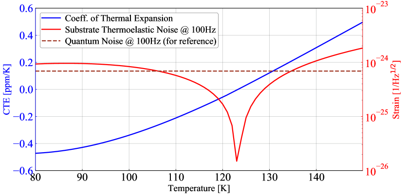
Thermo-elastic noise can be mitigated by holding the test mass at a temperature near absolute zero (20 K is sufficient for sapphire), where must vanish due to the Nernst heat theorem. Silicon has the unusual property that its thermo-elastic noise is also eliminated at an elevated temperature, 123 K, where crosses through zero [19] (see Figure 5).
To operate an interferometer at temperatures in the 10 – 20 K regime requires imposing an austere heat budget on the test mass, which in turn makes it difficult to achieve high circulating power in the arms [20, 11]. By contrast, at 123 K, the test mass heat budget is compatible with the use of megawatts of circulating power. This advance in optical power handling is what will allow us to also reduce the quantum noise, so as to realize the benefit of the improved thermal noise in 123 K silicon across a broad band of frequencies.
2.2 Size and composition
Large, high purity silicon crystals will be required for the LIGO Voyager test masses.
The size of the test mass affects the sensitivity in two ways. First, larger mirror surfaces enable larger optical spot sizes, thus reducing the coating thermal noise. Second, heavier masses suffer less disturbance from radiation pressure forces.
Impurities in the silicon can degrade the sensitivity. The most stringent known requirement derives from the production of free carriers (unbound electrons and holes) by these impurities and, ultimately, the impact this has on the cryogenic cooling system. To couple light into the arm cavities, a high-power beam must transmit through each input test mass. Some of the light interacts with free carriers inside the silicon substrate and is absorbed, heating up the test mass. High purity silicon is needed so that the heating due to free carrier absorption does not exceed the radiative cooling.
The size and composition of silicon crystals available to us are dictated by the commercially viable processes for crystal growth. Crystals with ultra-low contamination are produced using the float zone technique, but this process has not been scaled up to sizes greater than 20 cm in diameter. The magnetically stabilized Czochralski (MCZ) technique, on the other hand, yields 45 cm crystals that are somewhat less pure than float zone silicon [21]. MCZ silicon is the most promising candidate for producing test masses of the size needed for LIGO Voyager.
Oxygen is by far the most abundant impurity in MCZ silicon. It enters by diffusion from the fused silica crucible that holds the molten silicon, and is typically present at the level of or even higher. Most of this oxygen is interstitial to the lattice of silicon atoms, and does not affect the free carrier density. However, oxygen also forms complexes, referred to as “thermal donors”, that add free electrons. Rapid annealing may offer a way to disrupt oxygen complexes and eliminate some of the free carriers they contribute, which would otherwise be the dominant population in undoped MCZ silicon [22, 23, 24].
Other impurities include carbon, boron, and phosphorus. Carbon, typically found at , has little effect on the free carrier density. Boron and phosphorus are used as dopants to manipulate the carrier density, and they are found even in undoped silicon as contaminants with concentrations .
2.3 Absorption
Noteworthy absorption processes in silicon include inter-band absorption, two-photon absorption, and free carrier absorption. Due to the choice of wavelength and power density in the optics, the inter-band and two-photon absorption are found to be unimportant for LIGO Voyager [25, 26].
In the Drude model of free carrier response, the free carrier absorption is calculated as [27]:
| (1) |
with the optical wavelength, the elementary charge, the refractive index, the density of free carriers, the carrier effective mass, and the carrier mobility. (Note that the carrier density, mass, and mobility are different for electrons and holes.)
According to Equation 1, absorption of roughly 1 ppm/cm would be expected, if the level of residual boron and phosphorus doping available in MCZ silicon is the limiting factor. Absorption as low as 4.3 ppm/cm has been measured at 1550 nm in float zone silicon [28]. This result was in excess of the Drude model prediction, possibly due to the existence of an absorption band near 2300 nm in -type silicon [29]. Absorption measurements and annealing experiments on MCZ silicon samples are in progress, to better understand the mechanisms that limit absorption, and how thoroughly the contribution of oxygen can be suppressed.
2.4 Phase noise
The dominant phase noise term in the substrate is expected to be thermo-refractive noise. Like thermo-elastic noise, this noise is sourced by thermodynamic fluctuations of heat inside the material. The fluctuations are converted to refractive index fluctuations through the coefficient . The resulting phase noise is imposed on the light in the signal recycling cavity. The power spectral density of this noise has been estimated as [30]:
| (2) |
in units of signal recycling cavity displacement, for a Gaussian beam of radius , traversing an infinite plate with thickness , where is the density, is the specific heat capacity, and is the thermal conductivity. For LIGO Voyager, thermo-refractive noise is expected to be below the coating and quantum noise terms, but still within a factor of a few of limiting the sensitivity, as shown in Figure 4.
Analogously, the density of free carriers in silicon has an effect on the refractive index, so that thermodynamic fluctuations of the carrier density impose phase noise. The magnitude of this effect is described by a carrier dispersion coefficient (different for electrons and holes). The carrier density noise was estimated as [31]:
| (3) |
referred to signal recycling cavity displacement, where is the carrier diffusion coefficient (also different for electrons and holes), and is the Debye length. Although this noise has yet to be experimentally validated, the noise level was estimated to be less than , and thus is expected to be negligible for LIGO Voyager.
2.5 Scattering
The absorption, refractive index, birefringence, and surface profile of the test masses should all be uniform spatially, as far as possible. Any spatial inhomogeneity leads to scattering of the light that interacts with the test mass. Scattering is problematic because the loss of light can limit the buildup of optical power in the cavities. Even worse, scattered light often finds a path to return to the interferometer, thus contaminating the output with the ambient noise of all surfaces it encountered along the way.
The specific requirements on these characteristics will be determined as part of the detailed optical design of LIGO Voyager. The tolerable amount of scattered light will be smaller than specified for Advanced LIGO [32]. However, LIGO Voyager will also be less prone to wide-angle scattering, as discussed in section 4.2.2.
Spatial gradients in the atomic impurities discussed above are one likely source of inhomogeneity in MCZ silicon crystals. Another is microscopic crystal defects, such as voids, stacking faults, and SiO2 precipitates [33].
Impurity and defect populations can be manipulated during the crystal growth process, and also to some extent by annealing of the finished crystal. If we suppose that voids are the predominant defect population, approximated as spheres with a characteristic radius of 100 nm, then we can compute their scattering cross-section due to Mie scattering at wavelength 2000 nm. For a void concentration of , the resulting loss is estimated as 10 ppm per round trip through a LIGO Voyager test mass. Measurements to check the level of scatter loss in MCZ silicon crystals are underway [34].
2.6 Thermal lensing and active wavefront control
GW interferometers suffer from the detrimental effects of thermal gradients and distortion due to absorption of optical power [35, 36] in the surface and substrates of the core optics. LIGO Voyager is no exception, but the high thermal conductivity of silicon at cryogenic temperatures helps to mitigate this issue.
Analogous to the Advanced LIGO thermal compensation system [35], in LIGO Voyager there are two room-temperature silicon compensation plates in the recycling cavities, as illustrated in Figure 1, to which thermal actuation can be applied to correct for lensing in the substrates of the core optics. Room-temperature silicon is preferable to fused silica for the compensation plates for two reasons:
-
•
Silicon’s thermal lensing per watt is a factor of six greater at than at . Consequently there is much more actuation per watt in the compensation plate than distortion per watt in the test mass, yielding a comfortable measure of control on the thermal lensing.
-
•
Due to the increased absorption of mid-IR wavelengths (particularly at longer wavelengths), self-heating in a fused silica compensation plate may produce a larger thermal lens than the one to be corrected in the test mass (see Section 4.3.3 for details). Absorption in the room-temperature silicon compensation plates is expected to be comparable to that found in the test masses [29, 37].
Point absorbers on the reflective surface of the test mass have impaired the performance of Advanced LIGO [38]. However, LIGO Voyager will not suffer from this problem, as the coefficient of thermal expansion of the silicon test mass is effectively zero at . The surface deformation from point absorbers at full operating power is expected to be at least times smaller than in Advanced LIGO.
Finally, the current design has not specified a way to tune the radius of curvature of the test masses (in Advanced LIGO this tuning relies on a non-zero coefficient of thermal expansion). Unless such an actuator can be devised, the curvature error tolerance will be tighter than in Advanced LIGO. The curvature tolerance will be computed using a full simulation/model of the interferometer that includes the effects of control loops and higher order modes. This is still under development and beyond the scope of this design paper. However, we indicate here the considerations that will impact the tolerance specification:
-
•
optimizing the mode-matching between the two arm cavities (to minimize the differential loss),
-
•
optimizing the mode-matching to the two recycling cavities (to maximize power build up, signal bandwidth and squeezing efficiency),
-
•
ensuring the overall design of the arms is such that no higher order modes are close to resonant in the arms, and
-
•
ensuring the arm cavities are designed to minimize the number of parametric instabilities that have to be damped, see Section 4.4.2.
3 Optical Coatings
Gravitational wave interferometers use ion beam sputtered (IBS) thin films as the high reflectivity (HR) optical coatings on the test masses. These films are made of amorphous oxides [39]. After decades of development, these optical coatings now have excellent optical properties. Unfortunately, their internal friction (mechanical loss) is still large, and therefore, the concomitant Brownian noise is the limiting displacement noise in the Advanced LIGO design in the 40 – 200 Hz frequency band [40, 41].
Absorption of the interferometer beam in IBS coatings is problematic for interferometer operation because the resulting thermo-optic lenses alter the optical configuration from the nominal design. This problem has been present in all previous interferometer designs, and LIGO Voyager is no exception (see Section 2.6 for more details). However, optical absorption poses a special challenge for LIGO Voyager: when the heat load from absorbed optical power is coupled with cryogenic interferometer operation, a limit is placed on the maximum power stored in the interferometer.
This section describes the design of a cryogenic, amorphous-silicon-based, IBS coating for LIGO Voyager that decreases the coating Brownian noise by a factor of 4 compared to Advanced LIGO. In Section 3.2, we discuss the remarkably low mechanical loss of amorphous silicon at that makes this noise reduction possible. As it is relevant to the overall heat budget, the current state of absorption in amorphous silicon coatings is considered in Section 3.3.
3.1 Basic optical requirements
We begin with a brief review of the basic requirements for the test mass HR coatings.
-
•
45 cm diameter: the coatings must extend across the full diameter of the silicon test masses.
-
•
High reflectivity on ETM (Transmittance T = )
-
•
High reflectivity on ITM (T = 0.2%)
-
•
Low scatter loss ( per bounce)
- •
-
•
Reduction of Brownian noise by a factor of 4 or 5 from Advanced LIGO levels
-
•
At most 1ppm absorption, set by the heat budget of the test mass, see Appendix A.
3.2 Brownian noise
| Parameter | Detector | Material | Loss-angle | Refractive Index |
|---|---|---|---|---|
| () | ||||
| Low index | aLIGO (300 K) | SiO2 | 1.45 | |
| High index | aLIGO (300 K) | Ta2O5 | 2.07 | |
| Low index | Voyager (123 K) | SiO2 | 1.436 | |
| High index | Voyager (123 K) | -Si | [44] | 3.5 |
As described in [42], Brownian noise in the coating is the dominant residual noise source, particularly when thermo-optic noise is minimized. Brownian noise is driven by mechanical dissipation, where the relation between the dissipation and the noise is described by Callen’s Fluctuation-Dissipation Theorem [12, 13, 14]:
| (4) |
where is defined as the power spectral density of physical quantity . is the temperature of the mirror and is the complex mechanical admittance (the inverse of the mechanical impedance) associated with the radiation pressure force of the Gaussian intensity profile laser beam.
For a single layer coating, it can be shown that the Brownian noise spectrum is proportional to the mechanical loss angle, , of the layer. The Brownian noise of a multi-layer coating will involve the complex weighted sum of all the loss angles of all the layers.
3.2.1 Amorphous Silicon
Although almost all amorphous thin films suffer from a high level of internal friction, there is a film that has been made with nearly no such loss: amorphous silicon (-Si) [44, 46]. Recent measurements [47] have shown that amorphous silicon can be grown with both very low mechanical loss and low optical absorption at . Table 2 compares the loss angles for the Advanced LIGO and Voyager coating materials. Note that the loss angle, , for -Si is more than a factor of 20 lower than the high index material used in Advanced LIGO.
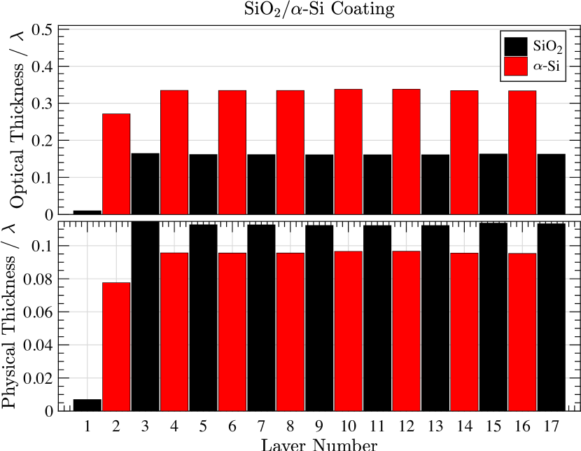
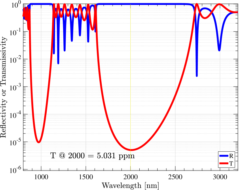
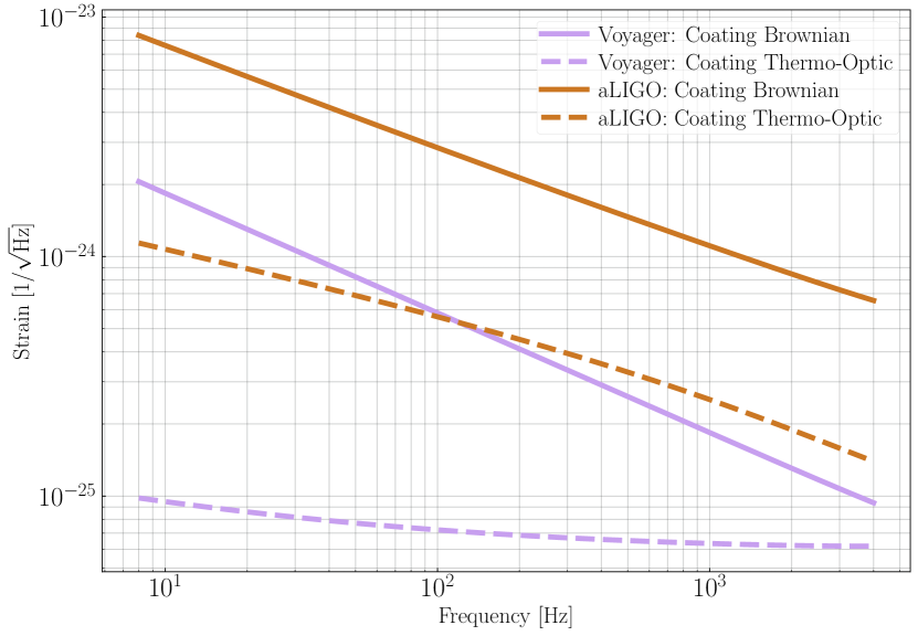
Using the material parameters for -Si:SiO2 at 123 K found in the literature, we have numerically optimized the layer structure so as to minimize the overall displacement noise while maintaining a low sensitivity to layer thickness variations (details of this technique can be found in [43]). The result is an ETM coating with 5 ppm transmission. Figure 6(a) shows the coating structure (notice that the design is close to, but not exactly, a simple stack of layers of thickness). The transmission and reflection spectra are shown in Figure 6(b). Finally, Figure 7 shows the Brownian and thermo-optic noises for Advanced LIGO and LIGO Voyager; Brownian noise is the limiting coating noise source for both, but it is more than 4 times lower for Voyager compared to aLIGO.
It is noteworthy that, unlike in today’s gravitational wave detectors, the contribution to the Brownian noise from the high refractive index (-Si) layers is so small that the low index (SiO2) layers become the dominant contributor to the noise.
3.2.2 Crystalline coatings
Crystalline coatings such as AlAs:GaAs [48] and AlGaP:GaP [49] have been shown to have a higher mechanical Q than amorphous dielectric coatings and, as such, are a favorable technology to pursue for high precision optical cavities. The thermo-optic noise of these coatings is generally high, but it can be mitigated by careful design of layer thicknesses [50]. Both crystalline coating options show promise as candidates for LIGO Voyager but require significant further development. AlGaP:GaP is lattice matched to silicon and could therefore be epitaxially grown directly onto a test mass substrate, but the absorption must be reduced to the 1 ppm level. AlAs:GaAs is not lattice matched to silicon so must be grown on a GaAs substrate and then lifted off [51] and affixed to the silicon test mass face, a technique yet to be demonstrated for 30 cm diameter coating stacks. While an -Si:SiO2 coating is the current choice for LIGO Voyager, breakthrough results on crystalline coatings could lead to a switch in design.
3.3 Optical absorption
The design of LIGO Voyager allows for 1 ppm absorption in the coatings of the test masses, stemming from the need to keep the core optics at cryogenic temperatures (see Appendix A). Much research has been performed in the last few years with the aim of lowering the optical absorption, although an -Si coating with absorption of less than 1 ppm at and 123 K has yet to be demonstrated. However, it appears likely this can be achieved, based on two recent results:
Taken together, these two results suggest that an -Si coating with less than 1 ppm absorption is feasible.
4 Choice of Laser Wavelength
The LIGO Voyager design uses silicon test masses, which are effectively opaque for wavelengths shorter than approximately . Thus, the laser wavelength used in first and second generation GW detectors () will not work in LIGO Voyager, and a new laser wavelength must be chosen.
As discussed in Section 7, we require approximately of single-frequency laser power at the input to the interferometer. These requirements (high power and low noise) demand a mature CW laser source. Within the 1400 – range, the main laser sources are telecommunication lasers at and thulium- and holmium-based sources in the 1800 – band. These are the wavelengths we will consider.
The laser wavelength affects the performance of virtually all the optical elements in the interferometer, many of which will directly impact the interferometer sensitivity, as discussed in the remainder of this section. Although many considerations enter into the choice between 1550 and , the decisive factor is the absorption in the mirror coatings. Selecting a longer wavelength, around , appears to be necessary in order to achieve the designed arm cavity power in LIGO Voyager, with other side effects being of secondary importance.
To justify a choice of wavelength, this section collects and discusses different physical processes (photodiode QE, coating absorption, substrate absorption, etc) that are discussed elsewhere in this manuscript. This section explores impacts solely with respect to wavelength; other sections explore these concepts individually and in a more multi-faceted way.
4.1 Quantum limits
For a fixed arm cavity power, the shot noise limited strain sensitivity at high frequencies degrades proportionally with the square root of the laser wavelength. Conversely, the radiation pressure limited strain sensitivity at low frequencies improves with increasing wavelength. From a quantum noise standpoint, increasing the laser wavelength by a factor of 2 is equivalent to lowering the arm cavity power by a factor of 2, all else being equal. However, the available arm cavity power is also constrained by other factors, primarily the coating absorption effect discussed above.
4.1.1 Photodetector quantum efficiency
High photodetector quantum efficiency (QE) is essential to make good use of high levels of squeezing. will be required for LIGO Voyager. At the time of writing, the QE of InGaAs photodetectors at is already sufficient to meet this requirement [54]. At , has yet to be demonstrated for InGaAs. Currently, is a better choice of wavelength from the perspective of QE. However, we know of no fundamental obstacle to achieving near-unity QE in photodetectors around . Photodetectors for are discussed in more detail in Section 5.4.
4.2 Noise Sources
4.2.1 Coating thermal noise
The coating layer structure and thickness depend upon the wavelength. In general, a longer operating wavelength requires a proportionally thicker coating, and so the coating thermal noise increases roughly as the square root of the wavelength. This implies a degradation in coating thermal noise at 2000 nm, relative to 1550 nm.
Amorphous silicon remains the best coating material available for NIR operations (from a thermal noise standpoint); however, the low index bilayer’s performance could be improved by changing from SiO2 to either alumina (Al2O3) or SiN which do not have the low temperature mechanical loss peaks.
4.2.2 Optical scatter loss and noise
For a mirror with a given roughness, the total power scattered into wide angles scales as [55]. We expect approximately 66% more loss via wide-angle scattering from vs. 333It is assumed that the roughness of the mirror coating is independent of the detailed coating layer structure. Advantages of reducing the scatter loss include:
-
•
a higher power recycling gain due to lower loss in the arm cavities
-
•
lower loss in the high-finesse, squeezing filter cavity
-
•
reduced backscattering noise (currently limiting all ground based detectors)
These in turn lead to reduced requirements on the input laser power, the length of the filter cavity, and scattered light beam baffles, respectively.
4.2.3 Residual gas noise
The phase noise due to residual gas in the main beam tubes [56, 57] is mainly due to H2 and N2, which have a negligible wavelength dependence in the NIR band. At atmospheric pressure, there are wide absorption bands 444https://www.gemini.edu/sciops/telescopes-and-sites/observing-condition-constraints/ir-transmission-spectra near 2000 nm due to water vapor. At UHV pressures, however, it can be assumed that there is no broadening of resonance linewidths due to particle collisions, but the distribution of particle velocities will create a Doppler resonance profile. The measured pressure for H2O in the LIGO beamtubes is 10-10 Torr; at this level any particular resonances can be avoided by tuning the main laser frequency by several GHz.
The atmospheric absorption is not an issue for the main interferometer, but could be an issue for some of the high power, in-air, laser systems. This issue would drive the laser wavelength higher (e.g. to 2128 nm) to where the absorption is minimal.
4.3 Absorption and Impact on Cryogenics
4.3.1 Absorption in the HR coatings
At 123 K, radiative cooling can extract at most of heat from the test masses, as described in Appendix A. To keep the heat budget in balance, we can tolerate no more than of absorbed power in the coating. With incident on the optical surfaces, absorption in the coatings must be very low (ppm) in order to maintain cryogenic temperature.
Measurements of absorption in amorphous silicon coatings show strong wavelength dependence, with the absorption being much higher at than at [52]. The physical mechanism for this is not well understood. However, at present it appears that will be the superior choice of wavelength to reach the objective of high power cryogenic operation.
4.3.2 Absorption in the test mass substrate
Substrate absorption is largely determined by the purity of the silicon material and its thermal history, as described in Section 2. According to Equation 1, the absorption is expected to scale with , being higher at than at . Substrate absorption is an important component of the heat budget for the input test masses, and the arm cavity finesse in LIGO Voyager will be substantially higher than in Advanced LIGO in order to manage this heat source. With the nominal design parameters (cf. Table 1), the heat load in the substrate of the ITM will be about a factor of three less than that due to the coating absorption. This ultimately drives the design towards longer wavelengths.
4.3.3 Absorption in auxiliary fused silica components
Fused silica will likely be the substrate material for all optics other the test masses and compensation plates. Absorption of optical power in fused silica, in the absence of OH in the glass, still occurs due to an intrinsic multi-phonon absorption process associated with the Si-O bonds in fused silica. This shows a large increase in absorption around [58, 59]. Absorption of optical power in these optics, most notably the beam-splitter (BS), will cause thermal lensing and loss of power without mitigation by thermal compensation [35]. For comparison, the estimates of the theoretical limits for absorption in fused silica [60] are approximately:
-
•
1 ppm/cm at , ( absorbed in BS)
-
•
20 ppm/cm at , ( absorbed in BS)
-
•
40 ppm/cm at , ( absorbed in BS)
-
•
90 ppm/cm at , ( absorbed in BS)
-
•
120 ppm/cm at , ( absorbed in BS)
versus 0.06 ppm/cm at (where the BS is thick and the substrate sees half of the in the PRC). The elevated absorption at the longer end of the wavelength range could present significant engineering challenges (strong thermal lenses, increased losses, power imbalance between the arms leading to increased technical noise couplings, increased contrast defect, etc). It may be possible to decrease the absorption by transitioning to glass made of a material with a heavier molecular mass, such as fluoride [61]. The technical challenges presented by wavelength dependent absorption are an active area of research requiring a full interferometer model to analyze the effects in a quantitative way. The results of this will impact the final choice of wavelength.
The absorption in fused silica opens up an intriguing prospect for an alternative thermal compensation design. Recent work in optical fibers [62] has demonstrated that by doping SiO2 with P2O5, which has a negative thermo-refractive coefficient equal to , it is possible to tune the of the resulting phosphosilicate glass. If we were to use fused silica compensation plates (instead of room-temperature silicon), the absorption of the interferometer laser in the glass coupled with a precisely tuned could be made to significantly cancel the thermal lens in the substrate of the test mass, thereby rendering the interferometer (mostly) thermally self-correcting.
4.4 Radiation Pressure Instabilities
4.4.1 Opto-Mechanical Angular Instability
Optical power, circulating in the arm cavities, applies torque on the mirrors and changes the dynamics of the suspended mirrors [63, 64, 65].
The magnitude of this radiation pressure induced optical torque depends upon the optical power and -factors of the cavities. The circulating power acts as a spring with either positive or negative stiffness. The sign of the feedback depends on the misalignment mode. In the case when two test masses have equal radius of curvature, a tilt of the axis produces a restoring torque; if the optical axis shifts, then radiation pressure torque tends to further misalign the mirrors. In one case the torque induced by radiation pressure makes the suspension mode stiffer (hard), while in the other case it tends to make the mode less stiff (soft).
Figure 8 shows the eigenfrequencies of hard and soft modes for different power levels. Here the nominal laser wavelength of for Voyager and for Advanced LIGO is assumed. When the optical power is high enough, the soft mode becomes unstable. A robust feedback control loop should have enough bandwidth to suppress the instability. Simulations show that if the frequency of the unstable mode is , then the bandwidth of the control loop needs to be , and significant filtering of the sensing noise ( dB) can be achieved at . Since the frequency of the soft mode is less than 1 Hz for the Voyager design at , sensing noise from angular loops should not limit the sensitivity.
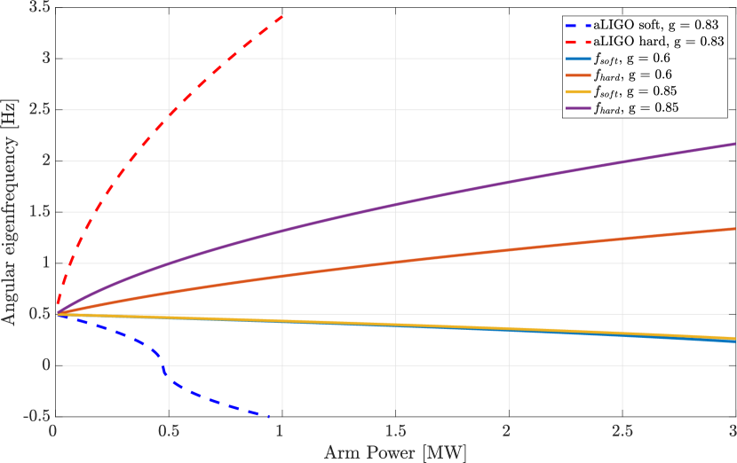
The hard/soft frequencies are functions only of the cavity -factors, and not explicitly the laser wavelength. However, if the laser beam spot size on the mirrors is kept to a maximum value, , due to clipping losses, then the cavity -factor will be smaller for a longer wavelength. Stated another way, if the beam spot size is maximized to reduce the thermal noise, the longer wavelength results in a more stable interferometer.
4.4.2 Parametric Instabilities
The optical cavities and the interferometer mirrors have high quality factors, which allow for highly amplified resonances in the system. The accidental overlap of the resonances can lead to parametric instabilities (PIs) [66]. As shown in Advanced LIGO, these are mostly mitigated by acoustic mode dampers (AMD) which are tuned masses bonded to piezo-electric transducers (PZTs) electrically connected to a dissipative element (resistor) [67]. It has been found that one order of magnitude suppression is easy to achieve.
Following the method of [67] we first compute the complex mechanical impedance of the mirrors. This model includes mechanical losses due to the coatings on the HR, anti-reflective (AR), and barrel surfaces. The baseline dimensions of the Voyager test mass have been used. The optical model considers the round trip optical gain, including scatter losses and clipping losses inside the arm cavities, as well as the optical transmissivities of the nominal LIGO Voyager design.
There are still open questions regarding operation of AMDs in Voyager. Since Voyager is a cryogenic detector, the material selection for the AMDs must be reconsidered. It is well known that PZT performance is strongly temperature dependent. The properties of PZTs and bonding epoxies at 123 K need to be examined.
In Figure 9, we assume the nominal operating wavelength and the concomitant test mass radii of curvature and cavity -factors. Our stability analysis shows that there would be about 65 unstable modes without the application of AMDs — significantly more than in Advanced LIGO. All of the unstable modes below 60 kHz are weakly unstable. As the damping efficacy of the AMDs has a frequency dependence, we feel confident that AMDs can be designed for LIGO Voyager which stabilize all of the modes without compromising the test mass thermal noise below 1 kHz. Most likely, the LIGO Voyager AMDs will use higher order mechanical resonances to damp the modes in a more frequency selective way. There is very little change in the number or strength of the instabilities as a function of laser wavelength in the 1800 – 2100 nm band 555Monte Carlo studies done of changing the Gouy phase of the power and signal recycling cavities, shows only a % variation in the number of unstable modes. .

4.5 Summary
The wavelength considerations for LIGO Voyager are summarized in Table 3. The color scheme varies through red, orange, yellow and green corresponding to a variation from negative to positive situations. As stated at the top of this section, and visually indicated in this table, the coating absorption favors a longer wavelength (around ), with absorption in fused silica potentially excluding longer wavelengths if it cannot be mitigated.
| Consideration | Wavelength | |||
|---|---|---|---|---|
| Photodiode Q.E. | %. Promising trajectory (Section 5.4). | |||
| Coating thermal noise | Low | 14% larger | ||
| Optical scatter loss | 66% larger | Low | ||
| Residual gas noise | low H2O | some H2O | low H2O | |
| Coating absorption | High | Medium | ||
| Si substrate absorption | Increases as but not dominant effect | |||
| SiO2 substrate absorption | ppm/cm | 20 ppm/cm | ppm/cm | 120 ppm/cm |
| Angular instability | Less stable | More stable arm cavity | ||
| Parametric instability | Very little change with wavelength | |||
5 Quantum Noise
LIGO Voyager, like Advanced LIGO, will be limited by quantum noise in the majority of its detection band, as illustrated in Figure 2. Extensive research has been carried out in the last decade to find solutions to reduce quantum noise in gravitational wave detectors. The main approach relevant to LIGO Voyager is squeezed light injection. Work has also been done on alternative interferometer optical topologies to recycled Michelson interferometers [68], but these are not discussed here. Squeezing is a well-tested technology and was demonstrated in GEO600 and in the H1 LIGO interferometer [69, 70, 71], in preparation for use in the second generation detectors like Advanced LIGO and Advanced Virgo.
Based on the analysis described in [72], the LIGO Voyager design relies on the injection of squeezed vacuum with a frequency dependent squeezing quadrature [73, 74, 75] as a solution to achieve a broadband reduction of quantum noise with respect to Advanced LIGO. This is illustrated in Figure 10 which shows frequency-dependent squeezing achieving a substantial improvement over the Advanced LIGO quantum noise floor. It can be seen that squeezing affords LIGO Voyager a factor of two or more improvement in sensitivity across virtually the whole detection band versus an unsqueezed LIGO Voyager.
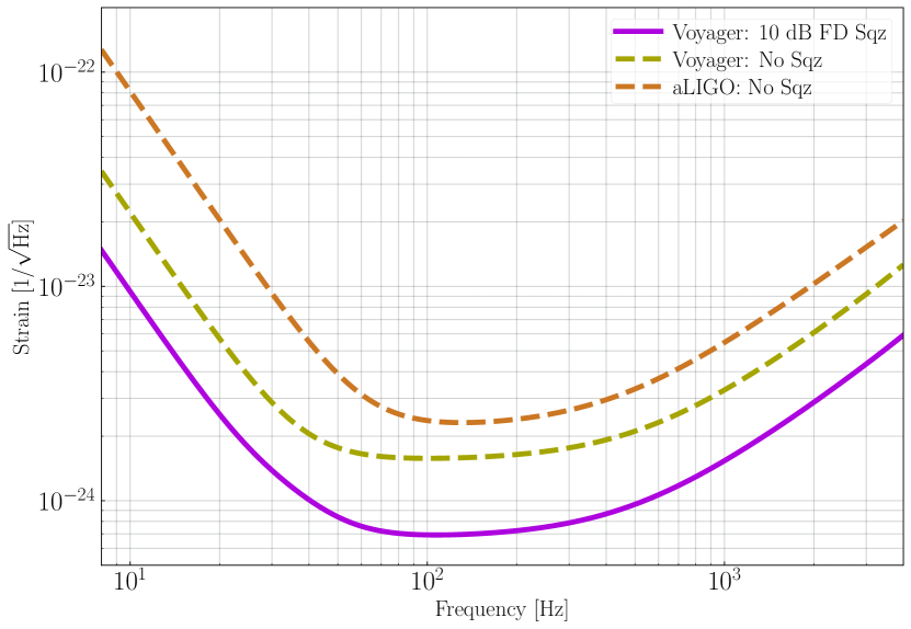
The design sensitivity curve shown in Figure 2 and Figure 10 are obtained by injection of of squeezing at 2000 nm into a 300 m long filter cavity with 10 ppm round-trip losses. The loss between the squeezed light source and the interferometer is 5%, while the detection efficiency is 95%, yielding approximately of effective squeezing.
To ensure that the squeezing design will be feasible for LIGO Voyager, we consider the state-of-the-art of three outstanding issues:
-
•
squeezed vacuum generation at ,
-
•
filter cavities for frequency-dependent squeezing in the audio band,
-
•
loss control for the squeezing system.
5.1 Squeezed vacuum generation for 2000 nm
By employing a coherent control scheme [76], as typically done to produce squeezing at in the audio frequency regime, high levels of squeezing down to 10 Hz should, in principle, be obtainable at different wavelengths. Indeed, high levels of squeezing at have already been demonstrated in the MHz regime (12.3 dB [54]) by pumping PPKTP at .
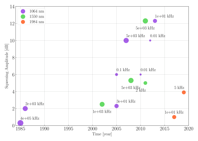
At the moment, no new technical difficulties peculiar to are anticipated and the best achieved squeezing to-date (at or near ) is 4 dB in the 1 – 40 kHz band, demonstrated with a laser source at [77]. This is illustrated in Figure 11 along with the history of squeezed light generation at different wavelengths (provided for reference).
5.2 Filter Cavities for Input Squeezing
Quantum noise appears in two forms: shot noise and radiation pressure (back-action) noise. Frequency-independent squeezed vacuum injection yields a reduction of high frequency quantum shot noise and a corresponding increase of low frequency quantum radiation pressure noise. In this form, squeezed vacuum injection (as in [70, 71]) will not be suitable for LIGO Voyager. However, squeezed vacuum can be manipulated to generate frequency-dependent squeezing by rotating the squeezed field relative to the interferometer field in a frequency dependent way. This can be achieved by reflecting the squeezed beam from a high finesse, detuned filter cavity before injection into the interferometer [74].
Filter cavities and their properties have been extensively studied theoretically [81, 82, 83]. The performance of a filter cavity can be characterized in terms of its intra-cavity losses per unit length. The lower the losses per unit length, the better the filter cavity is able to rotate the squeezing ellipse without degrading it. Direct measurements report round-trip losses of 10 ppm (5 ppm per bounce) for beam spot sizes in the 1 – 3 mm range (corresponding to confocal lengths of 5 – 25 m range), giving losses per unit length of 0.5 ppm/m with a 20 m long filter cavity [84].
Frequency dependent squeezing at has been experimentally demonstrated with rotation of the squeezing quadrature taking place around 1 kHz and squeezing levels of 5.4 dB and 2.6 dB observed at high and low frequency, respectively [75]. Technical noises (optical loss, phase noise) have been recently calculated in order to estimate realistic performance of a filter cavity [85].
The experimental characterization of the noise coupling mechanisms which limit the filter cavity performance is the next necessary milestone before validating this technology for application in gravitational wave detectors. The LIGO Scientific Collaboration has a program in place to achieve these goals for .
A similar program needs to be established for . A time scale of 3 years seems adequate to finalize a filter cavity design for LIGO Voyager, informed by the outcome of the on-going effort for .
5.3 Loss Control: General
In table top experiments, squeezing levels higher than 10 dB have been measured [80, 86, 87]. However, the measured squeezing in GW detectors is strongly dependent on the total loss that the squeezed beam encounters in the path from the squeezed light source to the measurement photodetector. In practice, in existing gravitational wave detectors, reducing these optical losses below 20% is non-trivial due to the large number of optical loss sources. For example, GEO600 reports [88] up to 4 dB of detected squeezing, corresponding to 40% total losses. LIGO Voyager will have to contend with the same practical issues.
Every optical loss in the path from the squeezed light source to the final photo-detector contributes vacuum fluctuations that degrade the squeezed state. The list of optical loss sources includes: squeezer optical parametric oscillator (OPO) internal losses, mode-mismatch, Faraday rotators and associated elements, signal- and arm-cavity losses, output mode cleaner (OMC) throughput and photodetector quantum efficiency (QE). To achieve 5% injection loss and 5%, readout loss, as currently assumed in the LIGO Voyager baseline curve, all of these loss sources need to be of the order of 0.5% – 2%.
Active mode-matching systems are currently in development for Advanced LIGO and we plan to continue development for LIGO Voyager. Continued effort is required to develop low-loss small optics for the OMC, polarizing components, OPO and Faraday isolators.
5.4 Loss Control: Quantum efficiency
One of the most challenging loss considerations at is the QE of photodiodes. The QE of the photodetectors used at the GW signal extraction ports must be >99% with a goal of 99.5%. Additionally, the high-QE photodiodes will need to remain linear and low-noise with approximately of optical power incident on them. Several options are available for detectors: extended InGaAs, mercury cadmium telluride (MCT or HgCdTe), and InAsSb, and these are discussed below. At this time, none of these options meets the high-QE, linearity, and low noise requirements, and significant development will be required on all these technologies to achieve better than 99% QE while simultaneously coping with the large amount of incident optical power.
5.4.1 Extended InGaAs photodetectors
Current extended InGaAs photodetectors typically have low QE (75%) around , although Laser Components Inc. has a series of photodiodes that have QE up to 87% [89].
Extended InGaAs photodiodes achieve a broader spectral response by varying the relative amounts of InAs and GaAs in the semiconductor alloy to increase the cut-off wavelength of the photodetector. Unfortunately, this leads to lattice spacing mismatch within the material that, in turn, results in significantly increased noise and, indirectly, lower QE. It is an active area of research to determine if QE can be increased in extended InGaAs without introducing catastrophic levels of low-frequency dark noise.
5.4.2 HgCdTe (MCT) photodetectors
Mercury cadmium telluride (MCT or HgCdTe) detectors are commonly used for infrared astronomy. They have a strong response in the mid-IR from 1.5 , with cut-off wavelengths of 2.5 , 5 or longer, depending on the construction. MCT detectors with an broadband AR coating have measured QE of approximately 94% [90].
As most MCT detectors are p-n junction based, they rely on diffusion of electrons and holes across the active region which is a (relatively) slow process and can lead to recombination of holes and electrons before they reach the junctions. Recombination results in an effective loss of QE as those charge carriers are ultimately not converted into photocurrent. MCT photodiodes could be promising in configurations other than p-n junction.
5.4.3 InAsSb photodetectors
InAsSb detectors have matured in the past two decades [91]. Traditionally low QE and high noise (when used at room temperature), InAsSb performance has improved in recent years by exploiting different junction architectures [92, 93, 94]. They are currently a promising candidate for further consideration.
5.5 Conclusion
The parts required for 10 dB of audio-band frequency-dependent squeezing at have yet to be demonstrated. Analogous demonstrations and the rate of technological development of squeezing over the last ten years, coupled with no fundamental reasons against, lead us to conclude that the LIGO Voyager squeezing design is achievable.
6 Suspensions
6.1 Introduction
The LIGO Voyager suspension system will have much in common with the Advanced LIGO suspension [95]. The basic quadruple pendulum design will be used. The upper two masses and their suspensions will be made from steel, and the lower two masses and suspension elements between them are made from a single material (silica in Advanced LIGO and silicon in LIGO Voyager). Hydroxide-catalysis bonding [96, 97] or optical contacting will be used to assemble the final monolithic stage. The three-stage seismic isolation system used in Advanced LIGO [98, 99] will be reused for LIGO Voyager, with minor engineering modifications to accommodate the heavier payload.
There are, however, two major differences between the Advanced LIGO suspensions and those of LIGO Voyager: (i) The silica cylindrical fiber final stage suspension will be replaced with silicon ribbons, and (ii) silicon cantilever blade springs for vertical isolation will be added to the final stage.
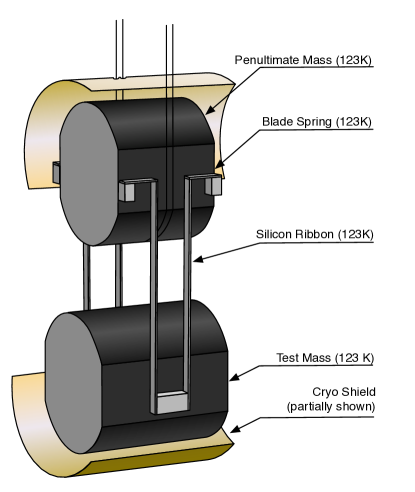
6.2 Suspension design
The lower two masses of the LIGO Voyager suspension will be cooled radiatively (Figure 12). The silicon test mass will be suspended by four silicon ribbons, via silicon vertical-spring blades attached to the silicon penultimate mass. This section between the test mass and the penultimate mass is conductively cooled by the cold masses. The cold section and the other upper masses are suspended with steel wires from the upper stages.
The mass distribution and suspension lengths have been designed to minimize the quadrature sum of the modeled seismic noise and suspension thermal noise at , as described in Table 4. The current seismic platform is able to support a payload of up to . In our design, was assigned to the main suspension chain, reserving for the reaction chain, the cage structure, and balancing mass. The total length of the main suspension chain from the top suspension point to the optical height of the test mass remains the same as Advanced LIGO.
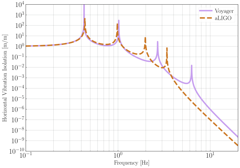
The resulting overall isolation of the suspension is shown in Figure 13. For a given total length of the suspension chain, the best vibration isolation above the pendulum resonant frequencies is realized with equal length stages [100]. However, we have chosen to make the bottom two stages as long as possible, so as to reduce the thermal noise from the penultimate stage (cf. Section 6.4). To maintain the seismic wall, the noise of the seismic platform can be improved through lower noise seismometers for the feedback control.
| aLIGO | LIGO Voyager | ||||
|---|---|---|---|---|---|
| Parameters | mass () | length () | mass () | length () | |
| Payload total | 124 | 1.642 | 1.642 | ||
| Top mass | 22 | 0.422 | |||
| Second mass | 22 | 0.277 | |||
| Penultimate mass | 40 | 0.341 | |||
| Final mass | 40 | 0.602 | |||
6.3 Fabrication of a monolithic silicon final stage
The final stage suspension will use silicon ribbons to suspend the silicon test mass from silicon vertical-spring blades bonded to the silicon penultimate mass. Crystalline silicon is the preferred material for the suspension, considering the thermal noise and the material matching with the mirror. Silica fibers like those of the second generation detectors are not suitable, because of their increased mechanical dissipation at low temperature [101, 102, 103, 104]. Not all of the engineering design of the monolithic stage has been determined. However, as discussed in Section 6.4, the thermal noise in this stage does not limit the sensitivity of the interferometer. It leaves plenty of room to relax the design requirements regarding the thermal noise to make the construction of this stage feasible.
6.3.1 Production of silicon ribbons
Silicon ribbons can be manufactured by cutting and etching a long silicon boule or a large wafer [105]. In the LIGO Voyager design, the ribbons have a width of and a thickness of . Since the test mass is cooled by radiation, the ribbon dimensions are determined purely by the tensile strength of silicon, and heat conduction is irrelevant. A review of silicon’s tensile strength can be found in [105]. There the measured tensile strengths range from to , depending on the dimensions of the ribbons, and the importance of the surface and edge quality is emphasized. Recent results under various surface treatments are found in [105] and [53], and there the average tensile strengths are distributed from to . We have assumed a tensile strength of to provide a safety factor, although stronger and thinner ribbons should become possible as the development progresses.
6.3.2 Hydroxide-catalysis bonding of the final stage
Instead of the laser welding used for fused silica suspensions, hydroxide-catalysis bonding (HCB) can be used for the assembly of the LIGO Voyager suspensions. HCB of oxide materials [96] was used in Gravity Probe B [106], and also to bond some glass parts to aLIGO test masses [95]. The same technique has been demonstrated to work on silicon [97]. The upper limit of the mechanical loss associated with the bonded silicon was reported to be [107]. The effect of this mechanical loss is not included in the thermal noise calculations here, and will have to be calculated by FEA. As with Advanced LIGO, we expect to only estimate the thermal noise using FEA and mechanical Q measurements, since the direct measurement of the suspension’s thermal noise is challenging even with the extremely low displacement noise of a gravitational wave interferometer.
6.3.3 Vertical suspension isolation
Vertical-spring blades are designed to lower the vertical resonant frequency and reduce the amount of vertical seismic and thermal noise coupling to the horizontal motion of the mirror. The bottom stage vertical springs will be made of silicon, for cryogenic compatibility, and they will be HCB-bonded to the penultimate mass and to the ribbon, as conceptually shown in Figure 12 (cf. the sapphire blades for KAGRA [108]).
As with silicon ribbons, the dimensions of the silicon vertical-spring blades will be determined by the breaking stress of silicon. If a breaking strength of is assumed, a -length -wide triangular blade with a thickness of can sustain of load. This blade would have a vertical spring constant of , and yields a rather high resonant frequency of . Further surface treatments of the blades should should allow us to increase the breaking strength and lower the vertical frequency.
6.4 Suspension thermal noise
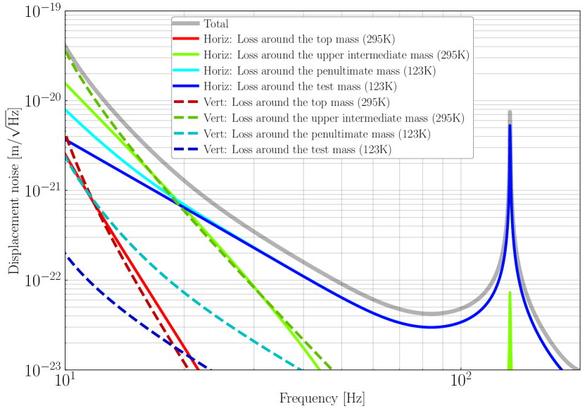
Figure 14 shows the current thermal noise estimate for a single test mass suspension, along with a breakdown of the losses associated with each suspension stage. This rough thermal noise model includes the bulk mechanical loss of the silicon and steel for the ribbons, wires, and blades, thermoelastic noise, and the surface loss effect of silicon. It does not include more detailed effects such as the mechanical loss associated with bonding, the shape factor of the ribbons and blades, couplings between the mechanical modes, etc. An increase in the suspension thermal noise relative to our rough estimates will result in a small increase in the overall LIGO Voyager noise at Hz, and a negligible impact on astrophysical metrics [109].
The total suspension thermal noise below is dominated by the penultimate stage wire, particularly its upper end which is attached to the upper intermediate mass. This is due to the high mechanical loss () of the steel wire, and the warm temperature of the mass. This noise cannot be mitigated by, for example, changing the wire material to fused silica or silicon. The penultimate stage has different temperatures for the upper and lower joints, and these alternate materials would suffer from excessive thermal noise at either the upper or the lower joint. To filter the noise from the penultimate stage, the lengths of the final two stages were made as long as possible (leaving as the minimum length of the upper stages). The noise of the final stage dominates above , but is very low due to the low mechanical loss and negligible thermal expansion of silicon at 123 K.
Another notable feature is the violin mode seen around , as determined by the size of the silicon ribbons. Further improvement of the tensile strength and optimization of the ribbon size is desirable, to move the violin modes higher.
7 Laser Technology
LIGO Voyager will operate at a laser wavelength in the range between and (see Section 4 for a full discussion of the wavelength choice). The final wavelength selection will depend both on other LIGO Voyager subsystem requirements and also on the development of near-IR and mid-IR lasers over the next several years. For simplicity in the following text, we refer to this wavelength range as .
In this section, we discuss the requirements and candidate technologies for the LIGO Voyager pre-stabilized laser. In considering those candidates, we will review the current state-of-the-art laser technology around . Commercial development of lasers within this wavelength range is of growing interest and is largely driven by remote sensing applications (e.g. spectroscopy of different gas species, particularly atmospheric CO2 and water [110]). Although promising free space and fiber lasers and amplifiers candidates exist, there is currently no commercial laser that meets all of the design specifications. This was also true when Initial and Advanced LIGO were in the same stages of development that LIGO Voyager is today and is not concerning: we expect mid-IR laser development to follow a similar trajectory to the one seen for lasers in Advanced LIGO.
7.1 Laser requirements
The requirements for the LIGO Voyager laser are summarized in Table 5.
| Type | Requirement | Comment |
|---|---|---|
| Wavelength | Single-frequency | |
| Power | CW operation | |
| Polarization* | horizontal, 100:1 ratio [111] | |
| Spatial mode* | 97% TEM00 [111] | |
| HOM content* | 3% [111] | |
| Intensity noise (RIN)* | Hz-1/2 | [112] |
| Hz-1/2 | [111] | |
| shot-noise limited | [111] | |
| Freq. noise (free-running)* | Hz-1/2 | [113] |
| Freq. actuation bandwidth* | [114] | |
| Operation | stable 365/24/7 | no maintenance required |
| Lifetime | 10+ years | continuous operation |
7.1.1 Power
The laser beam must deliver approximately of stabilized single frequency power at to the power-recycling mirror (PRM), as illustrated in Figure 1. Given that the total transmission of the input optics between the laser and PRM is approximately 70%, the required output of the laser is approximately .
The current laser design is broadly similar to the existing Advanced LIGO laser [113], based around three stages of increasing power:
-
•
Low power stage: requires a low intensity and phase noise, single-frequency, linearly polarized, CW, master oscillator laser with output power of approximately and good beam quality with mode content preferably >97%.
-
•
Medium power stage: the laser enters a medium power second stage in which it amplified to .
-
•
High power stage: the last stage of the laser system amplifies the output to .
The medium and high power stages must maintain the same low noise characteristics and good beam profile as the master oscillator.
7.1.2 Remaining requirements
Requirements for the higher-order mode (HOM) content and frequency and intensity noises are to be derived using a closed-loop, higher spatial order, opto-electronic feedback model of LIGO Voyager that includes realistic assumptions about absorption, thermal lensing and compensation based upon experiences with Advanced LIGO. At this time this model is still being developed. We use the Advanced LIGO laser requirements as a guide for upper limits to these requirements. These are listed in Table 5. These requirements are expected to be refined as realistic models of LIGO Voyager are developed.
The LIGO Voyager laser is expected to require at least a similar free-running frequency noise as Advanced LIGO. The frequency actuation bandwidth of the entire laser system must be approximately [114] in order to be able to sufficiently stabilize frequency fluctuations to the low-noise reference of the interferometer itself. It is not necessary for each stage (master oscillator, medium power stage and high power stage) to be individually capable of providing this bandwidth, provided that there is one or more component in the system that can.
The relative intensity noise (RIN) requirements, extending into the RF, are based on the intensity noise of the PSL in Advanced LIGO [111]. Once integrated into LIGO Voyager, the laser intensity noise will also be suppressed to a similar level to Advanced LIGO.
The laser is expected to run continuously without requiring major maintenance for the lifetime of the LIGO Voyager project, at least 10 years.
7.2 Laser candidate technologies and examples
There are two rare-earth dopants suitable for direct lasing at : thulium and holmium, which can provide optical amplification in the – [115], and – [116] bands, respectively.
Two basic laser architectures are available: optical fiber [117] and free-space [118] lasers. These architectures are not necessarily incompatible and the final system may contain a low-power free-space master oscillator (MO) followed by some combination of power oscillators and fiber amplifiers.
The following subsections detail examples of thulium and holmium lasers that are expected to meet the majority of the requirements for the LIGO Voyager laser.
7.2.1 Single-frequency, low-noise source
The full laser system begins with a master oscillator stage that is a low-noise, single-frequency source.
Fiber laser master oscillators use short lengths of doped silica fiber with spectrally-matched distributed-Bragg-reflector (DBR) fiber gratings [119] that are spliced onto each end. The gratings are fabricated to suit the required lasing wavelength of the Tm or Ho dopant, and thus a broad range of wavelengths are possible and modifying the wavelength of an otherwise suitable MO to satisfy other interferometer requirements should be possible. Achieving a stable, narrow linewidth MO will require careful thermal and vibration isolation of the fiber from the environment however.
Given that different wavelengths can be achieved, we must next consider the frequency noise. Determining if a commercial laser meets the frequency noise requirements from specifications alone is typically not possible as these lasers usually quote linewidth rather than frequency noise in their specifications. The single-frequency Q-Peak Firebow CW10-500, which has a linewidth of [120], is a possible candidate, but the stability and frequency noise would need to be measured to verify compatibility with LIGO Voyager requirements.
Alternatively, the free-space single-frequency non-planar ring oscillator (NPRO) architecture has been demonstrated to have low frequency noise, for example at [121]. This architecture uses a crystalline gain medium and thus only a few wavelengths are possible: a Tm:YAG NPRO at [122] and a NPRO at [123] have been reported but frequency noise spectra were not available at the time of writing. Additionally, lasing of cryogenic Tm:YAG at has been demonstrated [124] and is expected to be suitable for use in an NPRO.
Marginally outside the range is a laser. Lasers at this wavelength do not yet meet all the requirements for LIGO Voyager but could leverage existing components for frequency stabilization (when doubled and locked to the existing aLIGO lasers).
The existence of single-frequency, narrow linewidth, lasers is encouraging but more work needs to be done to determine if the frequency noise of these lasers meets the requirements of LIGO Voyager.
7.2.2 High power
High power lasers that could serve as amplifiers have been demonstrated. For example, a multi-mode, CW, Ho-doped fiber laser at has been demonstrated with power up to [125, 126]. Reviews of recent work in fiber lasers are provided by Hemming [116] and Fu [119].
High power free-space CW oscillators have also been demonstrated, including a Tm:YAG laser [ref] and a cryogenic Ho:YAG laser that produced a output at with good beam quality [127].
The closest example of an existing high-power low-noise laser is the , single-frequency single-mode thulium fiber laser demonstrated by Goodno et al. [128] that amplifies a linewidth distributed feedback laser diode from to greater than and maintains the low linewidth of the source. For this laser, stimulated Brillouin scattering (SBS) was demonstrated to be negligible below output power and, as such, is not expected to be an issue for the LIGO Voyager laser. Some early indications from high-power laser work at suggest that there may be power-dependent excess relative intensity noise at radio frequencies (RF) and this remains an active area of investigation.
7.3 Summary of laser prospects
Most of the constituent requirements of a pre-stabilized laser around (master oscillator, intermediate amplification and high power stages) have been demonstrated at or near this wavelength. Special emphasis needs to be placed upon acquiring frequency and intensity noise measurements on low-noise master oscillators soon.
It is clear that full confirmation of a laser source with sufficiently low frequency and intensity noise is still to be performed. We are confident that this can be achieved as the requirements for the LIGO Voyager laser are not substantially beyond specifications already demonstrated at other wavelengths [113]. Subsequent development and engineering work are still needed to integrate all these parts into a single system, however no fundamental reasons preclude the production of such a system.
8 Configurations
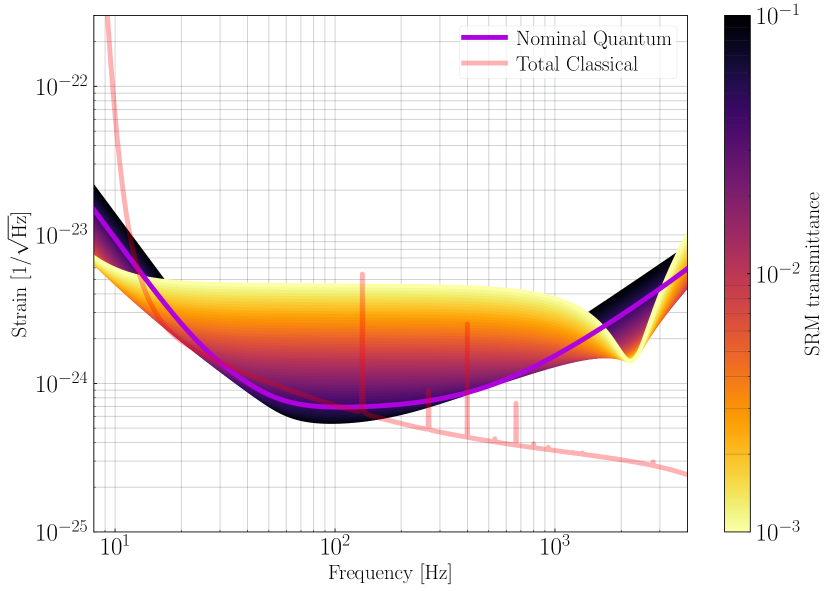
The nominal LIGO Voyager design is optimized for broadband operation by balancing quantum and classical noise sources, so as to maximize the number of detections of binary neutron star systems. Varying the signal recycling mirror (SRM) reflectivity will produce a different quantum noise floor. In this way, we can optimize for high frequency or low frequency operation, as is illustrated in Figure 15.
The nominal SRM transmittance, , is . In Figure 15, the interferometer has also been optimized for a range of transmittances between and 0.1. An SRM transmittance of 0.1 reduces the quantum noise in the band around . However, the quantum noise becomes lower than the classical noise in that band. As such, there will be limited overall sensitivity improvement without a significant reduction of classical (coating thermal) noise.
Conversely, if we use an SRM transmittance less than , we see improved sensitivity above , at the expense of broadband sensitivity. Such a configuration would be useful, for example, for exploring the neutron-star equation of state. The dip in noise around comes about because of the coupled cavity resonance between the arm and the signal recycling cavities [129].
9 Conclusion
We have described LIGO Voyager, a design concept for the next generation of ground based gravitational wave detector. The design takes advantage of large silicon mirrors, operated at high optical power and cryogenic temperatures, with quantum assisted metrology.
This instrument will extract the full potential of the existing LIGO facilities. Nearly all of the existing infrastructure (including the complex vibration isolation systems) will be re-used, greatly reducing the cost and complexity of the upgrade.
Much of the R&D required for LIGO Voyager has been ongoing for several years to support the cryogenic KAGRA and Einstein Telescope designs, and will also be applicable to the Cosmic Explorer design [130].
We anticipate that LIGO Voyager will open the next chapter of major discoveries in gravitational wave astronomy [109]. The upgraded detectors will find thousands of binary neutron stars, and detect stellar-mass binary black holes from throughout the cosmological era in which such mergers are believed to have taken place. The nearest sources will be detected with unprecedented clarity, providing highly sensitive probes of the behavior of ultra-dense matter and the nature of gravity itself.
This work was supported in part by the National Science Foundation under the LIGO cooperative agreement PHY-0757058. This paper has been assigned LIGO document number LIGO-P1800072.
Appendix A Cryogenics
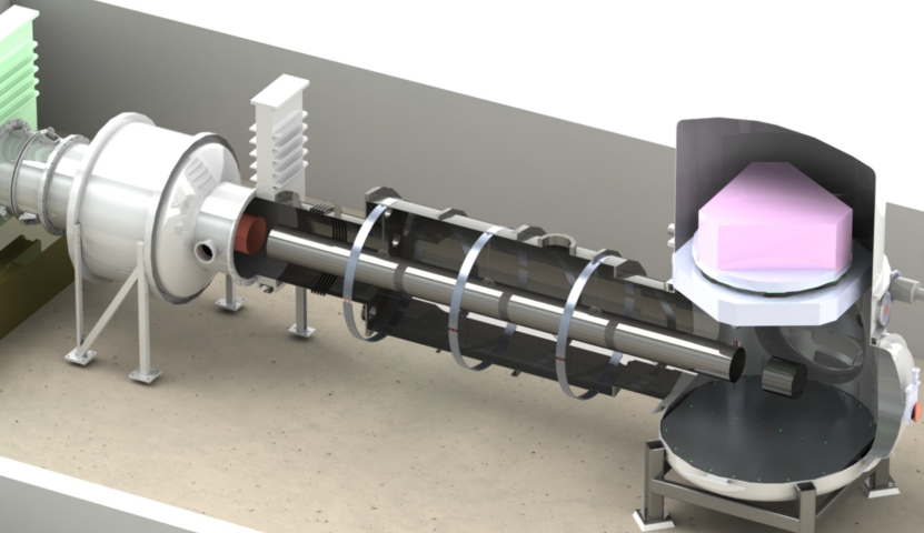
The cryogenic design concept for LIGO Voyager is discussed in [131]. The test masses are maintained at 123 K through radiative cooling, as illustrated in Figure 16. This approach was chosen to avoid complicating the test mass suspensions with the added requirements of a thermally conductive heat path.
A conductive heat path would require a mechanical link from the test mass through the suspension wires to the surrounding environment. Such a link would necessarily couple environmental vibrations into the suspension and through to the test mass. Moreover, minimizing the suspension wire cross-section is desirable to reduce the suspension thermal noise, but this would be at odds with the cryogenic design requirements (which favor thick, highly thermally conductive wires).
A.1 Heat Loads
The heat budget for the test mass includes several significant sources, which must be managed so as not to exceed the available radiative cooling power:
-
1.
absorption of the laser beam in the high reflectivity mirror coatings
-
2.
absorption of the laser beam in the bulk of the ITM silicon substrate
-
3.
thermal radiation from the room temperature, 4 km beam tube
-
4.
thermal radiation from the vacuum chambers near the test masses
-
5.
thermal radiation from nearby optics (reaction mass, compensation plate, arm cavity transmission monitor)
A.1.1 Absorption of the laser beam
Even 1 ppm of absorption in the high reflectivity coatings of the test masses will deliver significant heating, due to the large circulating power in the Fabry-Perot arm cavities. Assuming a circulating arm power , and coating absorption , the heat deposited into each test mass is
| (5) |
The input test masses of the arm cavities are transited by the circulating power in the power recycling cavity. Assuming a power incident on the beamsplitter , and substrate absorption in a test mass of depth , the heat deposited into each test mass is
| (6) |
A.1.2 Ambient environmental heating of the test mass
Cold windows in the arm cavities would prevent the mirrors from being exposed to the room temperature vacuum beam tube, but are not possible to include, for several reasons. First, the Fresnel reflections from even the best AR coatings would be in excess of the acceptable arm cavity loss of 10 ppm. Second, the beam heating of the window from the 3 MW of circulating power would introduce a large thermal lens, which would change as the circulating power is varied. Finally, the Brownian and thermo-optic noise of a window in the arm cavity would exceed the noise in the test masses.
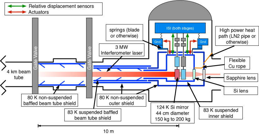
The radiant heating of the test mass can be largely mitigated by a cylindrical cold shield, extending out from the test mass to limit the solid angle at room temperature that the test mass ‘sees’. However, this shield cannot extend farther than the final gate valve separating the arm volume from the end station volume, at a distance of 10 m, as illustrated in Figure 17. The residual heating is given by the Stefan-Boltzmann law multiplied by the fraction of the full sphere subtended by the opening of the cylinder:
| (7) |
assuming that the length of the shield is m and the radius is m. This must be corrected for the non-black body emissivity of the HR surface. These parameters allow the heat load from the 300 K beam tube to be negligible.
A.2 Radiative cooling of the test mass
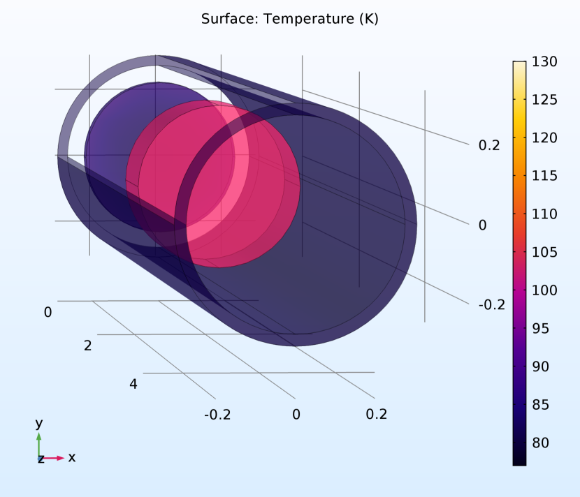
The effect of radiative cooling of the test mass into a 60 K environment has been estimated using a finite element model (see Figure 18). The model presumes that the HR and AR surfaces have emissivity , and the barrel has an emissivity of . At 123 K, the test mass can radiate 10 W.
A.2.1 Cold Shields
To minimize the radiative heat load from the 300 K beam tube, the radiation shield will need to include a cylindrical piece which extends into the beam tube. The inside of the shield will require baffles, as in the KAGRA design, to reduce multiple reflection paths from the 300 K environment [132].
The inside of the long shield should be coated with a high emissivity black coating to maximize the radiative coupling to the test mass. However, there is also the consideration of the 2 m light scattered from the arm cavity into the shield, and then scattered back into the arm cavity. This will be a source of amplitude and phase noise, and it is important that the high emissivity coating also has low BRDF so that scattered light noise is insignificant. Such an effect might be mitigated through the use of a combination of specular baffling and broadband absorption.
A second shield will be used outside of these blackened inner shields to reduce the large heat load from the 300 K environment. Both of the shields can be cooled conductively using soft thermal straps, which, in turn, are connected to Gifford-McMahon cryo-coolers outside of the vacuum system. These closed cycle cryo-coolers can cool the shields to approximately 50 – , and their vibrations can be isolated from the heat shields using simple spring mass assemblies.
References
- [1] B. P. Abbott, R. Abbott, T. D. Abbott, et al. Observation of gravitational waves from a binary black hole merger. Phys. Rev. Lett., 116:061102, Feb 2016.
- [2] B. P. Abbott, R. Abbott, T. D. Abbott, et al. Multi-messenger observations of a binary neutron star merger. Astrophys. J. Lett., 848(2):L12, oct 2017.
- [3] J. Miller, L. Barsotti, S. Vitale, et al. Prospects for doubling the range of Advanced LIGO. Phys. Rev. D, 91:062005, Mar 2015.
- [4] J. Harms. Terrestrial gravity fluctuations. Living Reviews in Relativity, 18(1), December 2015.
- [5] G. Cella. Off-line subtraction of seismic Newtonian noise. In Recent Developments in General Relativity, pages 495–503. Springer Milan, 2000.
- [6] J. C. Driggers, J. Harms, and R. X. Adhikari. Subtraction of Newtonian noise using optimized sensor arrays. Phys. Rev. D, 86:102001, Nov 2012.
- [7] P. Madau and M. Dickinson. Cosmic star-formation history. Annual Review of Astronomy and Astrophysics, 52(1):415–486, 2014.
- [8] J. Aasi, B. P. Abbott, R. Abbott, et al. Advanced LIGO. Classical and Quantum Gravity, 32(7):074001, mar 2015.
- [9] F. Acernese, M. Agathos, K. Agatsuma, et al. Advanced virgo: a second-generation interferometric gravitational wave detector. Classical and Quantum Gravity, 32(2):024001, dec 2014.
- [10] E. Hirose, D. Bajuk, G. Billingsley, et al. Sapphire mirror for the KAGRA gravitational wave detector. Phys. Rev. D, 89:062003, Mar 2014.
- [11] S. Hild, S. Chelkowski, A. Freise, et al. A xylophone configuration for a third-generation gravitational wave detector. Class. Quantum Grav., 27:015003, 2009.
- [12] H. B. Callen and T. A. Welton. Irreversibility and Generalized Noise. Phys. Rev., 83:34, 1951.
- [13] R. Kubo. The Fluctuation-Dissipation Theorem. Rep. Prog. Phys., 29:255–284, January 1966.
- [14] W. Bernard and H. B. Callen. Irreversible thermodynamics of nonlinear processes and noise in driven systems. Rev. Mod. Phys., 31:1017–1044, Oct 1959.
- [15] A. Schroeter, R. Nawrodt, R. Schnabel, et al. On the mechanical quality factors of cryogenic test masses from fused silica and crystalline quartz. arXiv preprint arXiv:0709.4359, 2007.
- [16] K. Numata and K. Yamamoto. Cryogenics. In G. Harry, T. P. Bodiya, and R. DeSalvo, editors, Optical Coatings and Thermal Noise in Precision Measurement, pages 108–128. Cambridge University Press, February 2012.
- [17] V. B. Braginsky, M. L. Gorodetsky, and S. P. Vyatchanin. Thermodynamical fluctuations and photo-thermal shot noise in gravitational wave antennae. Phys. Lett. A, 264:1, 1999.
- [18] Y. T. Liu and K. S. Thorne. Thermoelastic noise and homogeneous thermal noise in finite sized gravitational-wave test masses. Phys. Rev. D, 62:122002, 2000.
- [19] D. S. Kim, O. Hellman, J. Herriman, et al. Nuclear quantum effect with pure anharmonicity and the anomalous thermal expansion of silicon. Proceedings of the National Academy of Sciences, 115(9):1992–1997, 2018.
- [20] K. Somiya. Detector configuration of KAGRA–the Japanese cryogenic gravitational-wave detector. Class. Quantum Grav., 29(12):124007, 2012.
- [21] W. Lin and H. Huff. Silicon materials. In R. Doering and Y. Nishi, editors, Handbook of Semiconductor Manufacturing Technology, chapter 3. CRC Press, Boca Raton, 2008.
- [22] J. Michel and L. Kimerling. Electrical properties of oxygen in silicon. In R. Willardson, A. C. Beer, and E. R. Weber, editors, Oxygen In Silicon, volume 42 of Semiconductors and Semimetals, chapter 7, pages 251 – 287. Elsevier, 1994.
- [23] W. Götz, G. Pensl, W. Zulehner, R. C. Newman, and S. A. McQuaid. Thermal donor formation and annihilation at temperatures above 500∘C in Czochralski-grown Si. Journal of Applied Physics, 84(7):3561–3568, 1998.
- [24] G. Kissinger. Oxygen precipitation in silicon. In Defects and Impurities in Silicon Materials, pages 273–341. Springer Japan, 2015.
- [25] C. Schinke, P. Christian Peest, J. Schmidt, et al. Uncertainty analysis for the coefficient of band-to-band absorption of crystalline silicon. AIP Advances, 5(6):067168, 2015.
- [26] A. D. Bristow, N. Rotenberg, and H. M. v. Driel. Two-photon absorption and kerr coefficients of silicon for 850–2200nm. Applied Physics Letters, 90(19):191104, 2007.
- [27] R. Soref and B. Bennett. Electrooptical effects in silicon. IEEE Journal of Quantum Electronics, 23(1):123–129, January 1987.
- [28] J. Degallaix, R. Flaminio, D. Forest, et al. Bulk optical absorption of high resistivity silicon at 1550 nm. Opt. Lett., 38(12):2047–2049, Jun 2013.
- [29] W. Spitzer and H. Y. Fan. Infrared absorption in -type silicon. Phys. Rev., 108:268–271, Oct 1957.
- [30] V. B. Braginsky and S. P. Vyatchanin. Corner reflectors and quantum-non-demolition measurements in gravitational wave antennae. Phys. Lett. A, 324(5-6):345–360, April 2004.
- [31] F. Bruns, S. P. Vyachanin, J. Dickmann, et al. Thermal charge carrier driven noise in transmissive semiconductor optics. arXiv preprint arXiv:2003.05345, 2020.
- [32] G. Billingsley, G. Harry, and W. Kells. Core Optics Components Design Requirements Document. LIGO Technical Report, Caltech, https://dcc.ligo.org/LIGO-T000127/public, 2015.
- [33] J. Vanhellemont, K. Nakamura, E. Kamiyama, and K. Sueoka. Control of Intrinsic Point Defects in Single-Crystal Si and Ge Growth from a Melt. In Defects and Impurities in Silicon Materials, pages 181–240. Springer Japan, 2015.
- [34] Z. Tornasi. Optical properties of silicon for cryogenic interferferometric gravitational wave detectors. LIGO Technical Report, Caltech, https://dcc.ligo.org/LIGO-G1700998/public, 2017.
- [35] A. F. Brooks, B. Abbott, M. A. Arain, et al. Overview of advanced ligo adaptive optics. Appl. Opt., 55(29):8256–8265, Oct 2016.
- [36] W. Winkler, K. Danzmann, A. Rüdiger, and R. Schilling. Heating by optical absorption and the performance of interferometric gravitational-wave detectors. Phys. Rev. A, 44:7022–7036, December 1991.
- [37] J. Degallaix, J. Komma, D. Forest, et al. Measurement of the optical absorption of bulk silicon at cryogenic temperature and the implication for the einstein telescope. Classical and Quantum Gravity, 31(18):185010, aug 2014.
- [38] A. Brooks et al. P1900287: Point Absorbers in Advanced LIGO, in preparation. LIGO Technical Report, Caltech, https://dcc.ligo.org/LIGO-P1900287/public, 2019.
- [39] S. Reid and I. Martin. Development of Mirror Coatings for Gravitational Wave Detectors. Coatings, 6(4):61, December 2016.
- [40] M. Granata, E. Saracco, N. Morgado, et al. Mechanical loss in state-of-the-art amorphous optical coatings. Phys. Rev. D, 93:012007, Jan 2016.
- [41] L. Pinard, C. Michel, B. Sassolas, et al. Mirrors used in the ligo interferometers for first detection of gravitational waves. Appl. Opt., 56(4):C11–C15, Feb 2017.
- [42] M. Evans, S. Ballmer, M. Fejer, et al. Thermo-optic noise in coated mirrors for high-precision optical measurements. Phys. Rev. D, 78:102003, Nov 2008.
- [43] T. Hong, H. Yang, E. K. Gustafson, R. X. Adhikari, and Y. Chen. Brownian thermal noise in multilayer coated mirrors. Phys. Rev. D, 87:082001, Apr 2013.
- [44] X. Liu, D. R. Queen, T. H. Metcalf, J. E. Karel, and F. Hellman. Hydrogen-free amorphous silicon with no tunneling states. Phys. Rev. Lett., 113:025503, Jul 2014.
- [45] I. W. Martin, R. Nawrodt, K. Craig, et al. Low temperature mechanical dissipation of an ion-beam sputtered silica film. Class. Quantum Grav., 31(3):035019, jan 2014.
- [46] R. O. Pohl, X. Liu, and E. Thompson. Low-temperature thermal conductivity and acoustic attenuation in amorphous solids. Rev. Mod. Phys., 74:991–1013, Oct 2002.
- [47] R. Birney, J. Steinlechner, Z. Tornasi, et al. Amorphous silicon with extremely low absorption: Beating thermal noise in gravitational astronomy. Phys. Rev. Lett., 121:191101, Nov 2018.
- [48] G. D. Cole, W. Zhang, B. J. Bjork, et al. High-performance near- and mid-infrared crystalline coatings. Optica, 3(6):647–656, Jun 2016.
- [49] A. Cumming, A. Lin, A. Markosyan, et al. Epitaxial integration of monocrystalline III-V coatings on silicon for thermal noise reduction. Optical Interference Coatings (2013), paper MA.2, page MA.2, June 2013.
- [50] T. Chalermsongsak, E. D. Hall, G. D. Cole, et al. Coherent cancellation of photothermal noise in GaAs/Al0.92Ga0.08As Bragg mirrors. Metrologia, 53(2):860, April 2016.
- [51] E. Yablonovitch, D. M. Hwang, T. J. Gmitter, L. T. Florez, and J. P. Harbison. Van der waals bonding of gaas epitaxial liftoff films onto arbitrary substrates. Applied Physics Letters, 56:2419, 1990.
- [52] J. Steinlechner, I. W. Martin, A. S. Bell, et al. Silicon-based optical mirror coatings for ultrahigh precision metrology and sensing. Phys. Rev. Lett., 120:263602, Jun 2018.
- [53] R. Birney, A. V. Cumming, P. Campsie, et al. Coatings and surface treatments for enhanced performance suspensions for future gravitational wave detectors. Class. Quantum Grav., 34(23):235012, Nov 2017.
- [54] M. Mehmet, S. Ast, T. Eberle, et al. Squeezed light at 1550 nm with a quantum noise reduction of 12.3 dB. Opt. Express, 19(25):25763–25772, Dec 2011.
- [55] R. X. Adhikari. Integrated detector commissioning. Advanced Interferometric Gravitational-Wave Detectors. Volume I: Essentials of Gravitational-Wave Detectors. Edited by Reitze D et al. Published by World Scientific Publishing Co. Pte. Ltd., 2019. ISBN# 9789813146082, pp. 685-704, pages 685–704, 2019.
- [56] M. E. Zucker and S. E. Whitcomb. Measurement of optical path fluctuations due to residual gas in the ligo 40 meter interferometer. In Proceedings of the Seventh Marcel Grossman Meeting on General Relativity, Hackensack, N.J., 1996. World Scientific.
- [57] R. Takahashi, Y. Saito, M. Fukushima, et al. Direct measurement of residual gas effect on the sensitivity in TAMA300. Journal of Vacuum Science and Technology A: Vacuum, Surfaces, and Films, 20:1237, 2002.
- [58] W. Tropf, M. Thomas, and T. Harri. Properties of crystals and glasses. In Handbook of Optics: Devices, Measurements, and Properties, Volume II, Second Edition, chapter 33. IEEE, 1995.
- [59] R. Kitamura, L. Pilon, and M. Jonasz. Optical constants of silica glass from extreme ultraviolet to far infrared at near room temperature. Appl. Opt., 46(33):8118–8133, Nov 2007.
- [60] M. E. Thomas. Optical propagation in linear media: atmospheric gases and particles, solid-state components, and water. Johns Hopkins University/Applied Physics Laboratory series in science and engineering. Oxford University Press, Oxford ; New York, 2006. OCLC: ocm55729742.
- [61] M. Lines and P. Klocek. Optical transmission theory. In I. Aggarwal and J. Sanghera, editors, Infrared Fiber Optics, chapter 1, pages 1–30. CRC Press, 1998.
- [62] P. Dragic, M. Cavillon, and J. Ballato. On the thermo-optic coefficient of P2O5 in SiO2. Optical Materials Express, 7(10):3654, October 2017.
- [63] J. A. Sidles and D. Sigg. Optical torques in suspended Fabry Perot interferometers. Phys. Lett. A, 354:167–172, May 2006.
- [64] E. Hirose, K. Kawabe, D. Sigg, R. Adhikari, and P. R. Saulson. Angular instability due to radiation pressure in the LIGO gravitational-wave detector. Appl. Opt., 49(18):3474–3484, Jun 2010.
- [65] K. L. Dooley, L. Barsotti, R. X. Adhikari, et al. Angular control of optical cavities in a radiation-pressure-dominated regime: the Enhanced LIGO case. J. Opt. Soc. Am. A, 30(12):2618–2626, Dec 2013.
- [66] M. Evans, S. Gras, P. Fritschel, et al. Observation of parametric instability in Advanced LIGO. Phys. Rev. Lett., 114:161102, Apr 2015.
- [67] S. Gras, P. Fritschel, L. Barsotti, and M. Evans. Resonant dampers for parametric instabilities in gravitational wave detectors. Phys. Rev. D, 92:082001, Oct 2015.
- [68] E. Knyazev, S. Danilishin, S. Hild, and F. Khalili. Speedmeter scheme for gravitational-wave detectors based on EPR quantum entanglement. Phys. Lett. A, 382(33):2219 – 2225, 2018. Special Issue in memory of Professor V.B. Braginsky.
- [69] H. Grote, K. Danzmann, K. L. Dooley, et al. First Long-Term Application of Squeezed States of Light in a Gravitational-Wave Observatory. Phys. Rev. Lett., 110(18):181101, May 2013.
- [70] T. L. S. Collaboration, J. Abadie, B. P. Abbott, et al. A gravitational wave observatory operating beyond the quantum shot-noise limit. Nat. Phys., 7:962 EP –, 09 2011.
- [71] J. Aasi, J. Abadie, B. P. Abbott, et al. Enhanced sensitivity of the LIGO gravitational wave detector by using squeezed states of light. Nat. Photonics, 7(8):613–619, August 2013.
- [72] H. Miao, H. Yang, R. X. Adhikari, and Y. Chen. Quantum limits of interferometer topologies for gravitational radiation detection. Class. Quantum Grav., 31(16):165010, aug 2014.
- [73] W. G. Unruh. Quantum noise in the interferometer detector. In Quantum Optics, Experimental Gravity, and Measurement Theory, pages 647–660. Springer, 1983.
- [74] H. J. Kimble, Y. Levin, A. B. Matsko, K. S. Thorne, and S. P. Vyatchanin. Conversion of conventional gravitational-wave interferometers into quantum nondemolition interferometers by modifying their input and/or output optics. Phys. Rev. D, 65:022002, 2001.
- [75] E. Oelker, T. Isogai, J. Miller, et al. Audio-band frequency-dependent squeezing for gravitational-wave detectors. Phys. Rev. Lett., 116:041102, Jan 2016.
- [76] H. Vahlbruch, S. Chelkowski, B. Hage, et al. Coherent control of vacuum squeezing in the gravitational-wave detection band. Phys. Rev. Lett., 97:011101, Jul 2006.
- [77] G. L. Mansell, T. G. McRae, P. A. Altin, et al. Observation of squeezed light in the region. Phys. Rev. Lett., 120:203603, May 2018.
- [78] R. E. Slusher, L. W. Hollberg, B. Yurke, J. C. Mertz, and J. F. Valley. Observation of squeezed states generated by four-wave mixing in an optical cavity. Phys. Rev. Lett., 55:2409–2412, Nov 1985.
- [79] L.-A. Wu, H. J. Kimble, J. L. Hall, and H. Wu. Generation of squeezed states by parametric down conversion. Phys. Rev. Lett., 57:2520–2523, Nov 1986.
- [80] H. Vahlbruch, M. Mehmet, S. Chelkowski, et al. Observation of squeezed light with 10-dB quantum-noise reduction. Phys. Rev. Lett., 100:033602, Jan 2008.
- [81] J. Harms, Y. Chen, S. Chelkowski, et al. Squeezed-input, optical-spring, signal-recycled gravitational-wave detectors. Phys. Rev. D, 68(4):042001, 2003.
- [82] F. Y. Khalili. Optimal configurations of filter cavity in future gravitational-wave detectors. Phys. Rev. D, 81:122002, Jun 2010.
- [83] M. Evans, L. Barsotti, P. Kwee, J. Harms, and H. Miao. Realistic filter cavities for advanced gravitational wave detectors. Phys. Rev. D, 88(2):022002, 2013.
- [84] T. Isogai, J. Miller, P. Kwee, L. Barsotti, and M. Evans. Loss in long-storage-time optical cavities. Opt. Express, 21(24):30114–30125, Dec 2013.
- [85] P. Kwee, J. Miller, T. Isogai, L. Barsotti, and M. Evans. Decoherence and degradation of squeezed states in quantum filter cavities. Phys. Rev. D, 90:062006, Sep 2014.
- [86] M. S. Stefszky, C. M. Mow-Lowry, S. S. Y Chua, et al. Balanced homodyne detection of optical quantum states at audio-band frequencies and below. Class. Quantum Grav., 29(14):145015, July 2012.
- [87] L. Barsotti, J. Harms, and R. Schnabel. Squeezed vacuum states of light for gravitational wave detectors. Rep. Prog. Phys., 82(1):016905, dec 2018.
- [88] K. Dooley, J. Leong, T. Adams, et al. GEO 600 and the GEO-HF upgrade program: successes and challenges. Class. Quantum Grav., 33(7):075009, 2016.
- [89] Laser Components Inc. Manufacturer’s note: InGaAs PIN Photodiodes, 2016.
- [90] Teledyne Scientific and Imaging. Manufacturer’s note: SWIR PV MCT detectors, 2.5 m, high performance at room temp, 2017.
- [91] P. Martyniuk, J. Antoszewski, M. Martyniuk, L. Faraone, and A. Rogalski. New concepts in infrared photodetector designs. Appl. Phys. Rev., 1:041102, 2014.
- [92] P. Klipstein, O. Klin, S. Grossman, et al. XBn barrier photodetectors based on InAsSb with high operating temperatures. Optical Engineering, 50(6):1 – 11 – 11, 2011.
- [93] D. Z.-Y. Ting, A. Soibel, C. J. Hill, et al. Antimonide superlattice complementary barrier infrared detector (cbird). Infrared Physics & Technology, 54(3):267 – 272, 2011. Proceedings of the International Conference on Quantum Structure Infrared Photodetector (QSIP) 2010.
- [94] E. H. Steenbergen, B. C. Connelly, G. D. Metcalfe, et al. Significantly improved minority carrier lifetime observed in a long-wavelength infrared III-V type-II superlattice comprised of InAs/InAsSb. Appl. Phys. Lett., 99(25):251110, 2011.
- [95] S. M. Aston, M. A. Barton, A. S. Bell, et al. Update on quadruple suspension design for Advanced LIGO. Class. Quantum Grav., 29(23):235004, 2012.
- [96] S. Rowan, S. Twyford, J. Hough, D.-H. Gwo, and R. Route. Mechanical losses associated with the technique of hydroxide-catalysis bonding of fused silica. Phys. Lett. A, 246(6):471 – 478, 1998.
- [97] A. A. v. Veggel, J. Scott, D. A. Skinner, et al. Strength testing and SEM imaging of hydroxide-catalysis bonds between silicon. Class. Quantum Grav., 26(17):175007, 2009.
- [98] S. Wen, R. Mittleman, K. Mason, et al. Hydraulic external pre-isolator system for LIGO. Class. Quantum Grav., 31(23):235001, December 2014.
- [99] F. Matichard, B. Lantz, R. Mittleman, et al. Seismic isolation of Advanced LIGO: Review of strategy, instrumentation and performance. Class. Quantum Grav., 32(18):185003, September 2015.
- [100] B. Shapiro, D. Madden-Fong, and B. Lantz. LIGO Voyager Quad Pendulum Conceptual Design Optimization. LIGO Technical Report, Caltech, https://dcc.ligo.org/LIGO-T1300786/public, 2014.
- [101] O. L. Anderson and H. E. Bömmel. Ultrasonic Absorption in Fused Silica at Low Temperatures and High Frequencies. Journal of the American Ceramic Society, 38(4):125–131, April 1955.
- [102] M. E. Fine, H. Van Duyne, and N. T. Kenney. Low-Temperature Internal Friction and Elasticity Effects in Vitreous Silica. J. Appl. Phys., 25(3):402–405, May 2004.
- [103] J. W. Marx and J. M. Sivertsen. Temperature Dependence of the Elastic Moduli and Internal Friction of Silica and Glass. J. Appl. Phys., 24(1):81–87, June 2004.
- [104] H. J. McSkimin. Measurement of Elastic Constants at Low Temperatures by Means of Ultrasonic Waves–Data for Silicon and Germanium Single Crystals, and for Fused Silica. J. Appl. Phys., 24(8):988–997, June 2004.
- [105] A. V. Cumming, L. Cunningham, G. D. Hammond, et al. Silicon mirror suspensions for gravitational wave detectors. Class. Quantum Grav., 31(2):025017, January 2014.
- [106] S. Buchman, F. Everitt, B. Parkinson, et al. Experimental techniques for gyroscope performance enhancement for the Gravity Probe B relativity mission. Class. Quantum Grav., 13(11A):A185–A191, November 1996.
- [107] L. Prokhorov, D. Koptsov, M. Matiushechkina, et al. Upper limits on the mechanical loss of silicate bonds in a silicon tuning fork oscillator. Phys. Lett. A, 382:2186–2191, 2018.
- [108] R. Kumar, D. Chen, A. Hagiwara, et al. Status of the cryogenic payload system for the KAGRA detector. Journal of Physics: Conference Series, 716(1):012017, May 2016.
- [109] R. X. Adhikari, P. Ajith, Y. Chen, et al. Astrophysical science metrics for next-generation gravitational-wave detectors. Class. Quantum Grav., 36, 2019.
- [110] K. Scholle, S. Lamrini, P. Koopmann, and P. Fuhrberg. 2 m laser sources and their possible applications. In B. Pal, editor, Frontiers in Guided Wave Optics and Optoelectronics, chapter 21, pages 471–500. InTechOpen, February 2010.
- [111] B. Willke, P. King, R. Savage, and P. Fritschel. Pre-Stabilized Laser Design Requirements. LIGO Technical Report, Caltech, https://dcc.ligo.org/LIGO-T050036/public, 2011.
- [112] M. Heurs, V. M. Quetschke, B. Willke, K. Danzmann, and I. Freitag. Simultaneously suppressing frequency and intensity noise in a Nd:YAG nonplanar ring oscillator by means of the current-lock technique. Opt. Lett., 29(18):2148–2150, Sep 2004.
- [113] P. Kwee, C. Bogan, K. Danzmann, et al. Stabilized high-power laser system for the gravitational wave detector advanced LIGO. Opt. Express, 20(10):10617–10634, May 2012.
- [114] E. Hall. Long-baseline laser interferometry for the detection of binary black-hole mergers. PhD thesis, California Institute of Technology, 2016.
- [115] A. Sincore, J. D. Bradford, J. Cook, L. Shah, and M. C. Richardson. High average power thulium-doped silica fiber lasers: Review of systems and concepts. IEEE Journal of Selected Topics in Quantum Electronics, 24(3):1–8, 2018.
- [116] A. Hemming, N. Simakov, J. Haub, and A. Carter. A review of recent progress in holmium-doped silica fibre sources. Optical Fiber Technology, 20:621–630, 2014.
- [117] A. Hemming, N. Simakov, J. Haub, and A. Carter. Thulium and holmium doped fibre lasers for 2 micron applications. In Workshop on Specialty Optical Fibers and Their Applications, page WT1A.3. Optical Society of America, 2015.
- [118] M. Ganija, N. Simakov, A. Hemming, et al. Efficient, low threshold, cryogenic Ho:YAG laser. Opt. Express, 24(11):11569–11577, May 2016.
- [119] S. Fu, W. Shi, Y. Feng, et al. Review of recent progress on single-frequency fiber lasers [invited]. J. Opt. Soc. Am. B, 34(3):A49–A62, Mar 2017.
- [120] Q-Peak, Inc. Firebow CW10-500 Tm:Fiber CW Laser, 2018.
- [121] B. Willke, S. Brozek, K. Danzmann, V. Quetschke, and S. Gossler. Frequency stabilization of a monolithic Nd:YAG ring laser by controlling the power of the laser-diode pump source. Opt. Lett., 25(14):1019–1021, Jul 2000.
- [122] Z. Lin, C. Gao, M. Gao, et al. Diode-pumped single-frequency Tm:YAG NPRO laser by using different pumping spot sizes. Frontiers of Optoelectronics in China, 2(4):410, Oct 2009.
- [123] B.-Q. Yao, X.-M. Duan, D. Fang, et al. 7.3 W of single-frequency output power at 2.09 m from an Ho:YAG monolithic nonplanar ring laser. Opt. Lett., 33(18):2161–2163, Sep 2008.
- [124] L. F. Johnson, J. E. Geusic, and L. G. Van Uitert. Coherent oscillations from , , and ions in yttrium aluminum garnet. Appl. Phys. Lett., 7(5):127–129, 1965.
- [125] A. Hemming, S. Bennetts, N. Simakov, et al. High power operation of cladding pumped holmium-doped silica fibre lasers. Opt. Express, 21(4):4560–4566, Feb 2013.
- [126] N. Simakov, A. Hemming, J. Haub, and A. Carter. High power holmium fiber lasers. In The European Conference on Optical Communication (ECOC), page Tu.3.4.1, 2014.
- [127] M. Ganija, A. Hemming, N. Simakov, et al. High power cryogenic Ho:YAG laser. Opt. Express, 25(25):31889–31895, Dec 2017.
- [128] G. D. Goodno, L. D. Book, and J. E. Rothenberg. Low-phase-noise, single-frequency, single-mode 608 w thulium fiber amplifier. Opt. Lett., 34(8):1204–1206, Apr 2009.
- [129] D. Martynov, H. Miao, H. Yang, et al. Exploring the sensitivity of gravitational wave detectors to neutron star physics. Phys. Rev. D, 99:102004, May 2019.
- [130] D. Reitze et al. Cosmic Explorer: The U.S. Contribution to Gravitational-Wave Astronomy beyond LIGO. arXiv preprint arXiv:1907.04833, 2019.
- [131] B. Shapiro, R. X. Adhikari, O. Aguiar, et al. Cryogenically cooled ultra low vibration silicon mirrors for gravitational wave observatories. Cryogenics, 81:83–92, January 2017.
- [132] Y. Sakakibara, N. Kimura, T. Akutsu, T. Suzuki, and K. Kuroda. Performance test of pipe-shaped radiation shields for cryogenic interferometric gravitational wave detectors. Class. Quantum Grav., 32(15):155011, 2015.