An Analytical Model for Efficient Indoor THz Access Point Deployment ††thanks: This project was funded by CMU Portugal Program: CMU/TMP/0013/2017- THz Communication for Beyond 5G Ultra-fast Networks.
ABSTRACT
Ultra-densification of user equipment (UE) and access points (APs) are anticipated to take a toll on the future spectrum needs. Higher frequency bands, such as mmWave (-) and THz spectrum (-), can be used to cater to the high-throughput needs of ultra-dense networks. These high-frequency bands have a tremendous amount of green-filed contiguous spectrum, ranging in hundreds of . However, these bands, especially the THz bands, face numerous challenges, such as high spreading, absorption, and penetration losses. To combat these challenges, the THz-APs need to be either equipped with high transmit power, high antenna gains (i.e., narrow antenna beams), or limit the communication to short-ranges. All of these factors are bounded due to technical or economic challenges, which will result in a “distance-power dilemma” while deciding on the deployment strategy of THz-APs. In this paper, we present an analytical model to deploy THz-APs in an indoor setting efficiently. We further show through extensive numerical analysis, the optimal number of APs and optimal room length for different blocks of the THz spectrum. Furthermore, these THz-APs need to be efficiently packed to avoid outages due to handoffs, which can add more complexity to the dilemma. To mitigate the packing problem, we propose two solutions over the optimal solution: (a) Radius Increase, and (b) Repeater Assistance, and present an analytical model for each.
Keywords
Terahertz (THz), Indoor AP Placement, Energy Efficient, Spectrum Efficient, AP Fitting, Lambert’s W-function
| Center Frequencies in | |||||||||||
| Contiguous Bandwidth in | |||||||||||
| Required Power in dB | |||||||||||
I Introduction
A report by the International Telecommunication Union-Recommendation (ITU-R) predicts by the year 2030, the number of global mobile subscriptions will reach nearly , on which live and on-demand video will account for a significant portion of the traffic [1]. Although it is hard to predict years out concerning the specific user demands and needs, it is evident that to accommodate such ultra-dense networks, more spectrum will be required. Many applications, such as live streaming, on-demand video, online gaming, virtual reality (VR) and augmented reality (AR), are dependent on the availability of low-latency and high-throughput wireless access. Obtaining more spectrum in the lower and mid bands will be beneficial for this purpose. However, in the US, the mid-bands are highly occupied, and repurposing of the spectrum will take time, which can hinder the progress of technology. Moving to higher frequency bands, like THz spectrum (), can help facilitate the advancement of technology and satisfy the growing demand.
As we move higher in the frequency, losses such as spreading with distance, absorption due to water vapor, and penetration through objects, increases, which can limit the effective communication to short ranges, i.e., [2]. THz spectrum is sandwiched between the microwave and infrared bands, which makes it both beneficial and challenging for deployment [2, 3, 4]. On the one hand, THz is not so sensitive to particles and objects compared to infrared bands, while, on the other hand, it has more green-filed contiguous spectrum compared to mmWave bands. THz frequency cannot be extensively used in outdoor settings like traditional RF bands, except for some unique use-cases [5]. However, THz-APs can be deployed indoors with dense coverage of users requiring ultra-low-latency and ultra-high-throughput.
I-A The Dilemma
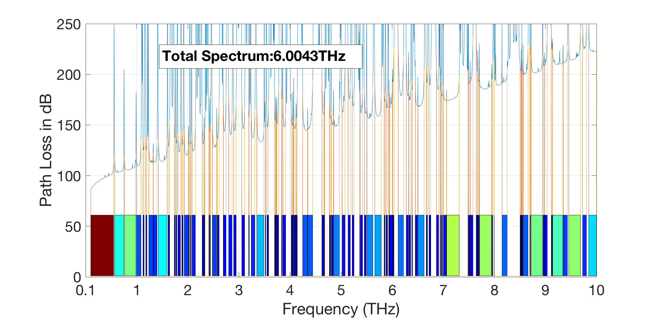
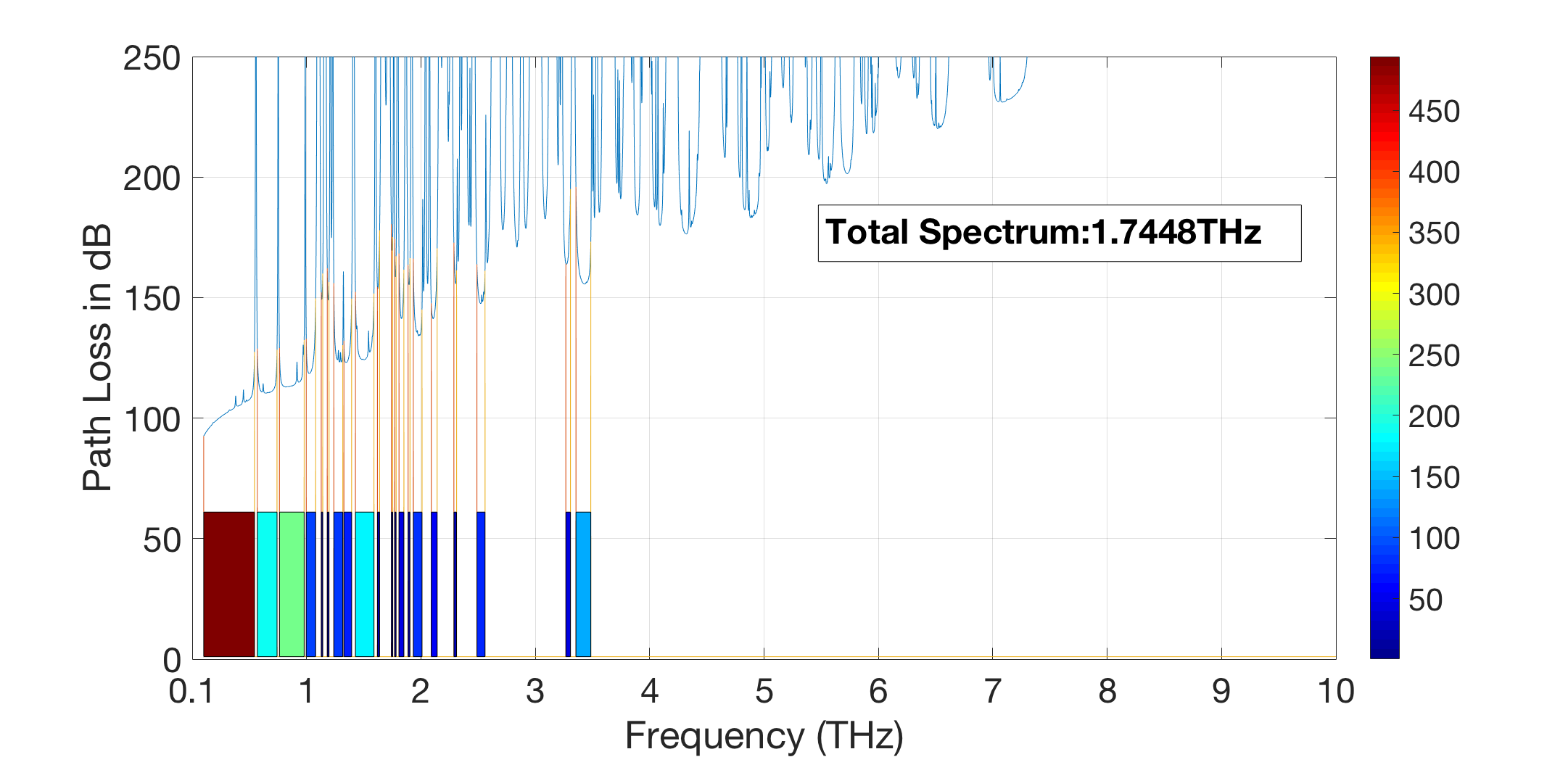
Although THz has an abundance of the spectrum, nearly , which is more than what we can ever achieve in the lower RF bands, the total usable spectrum is dependent on environmental parameters and specific use cases. THz frequencies are sensitive to molecular absorption, like and , which results in a tremendous amount of path loss. As shown in Fig. 1, the total usable spectrum diminishes from (Fig. 1(a)) to (Fig. 1(b)) when we increase the separation from to . The sensitivity analysis shown in Fig. 1 is dependent on the environment and the transceiver properties. In case of high humid scenarios ( when humans exhale) or poor hardware (which cannot cut-off such narrow spikes), the usable spectrum will reduce drastically. Thus, there is a need to use this spectrum more efficiently.
Based on our sub-channel analysis shown in Fig. 1, we divide the THz spectrum into bands, which are apart and identify as prospective carrier frequencies with the maximum available contiguous sub-channel bandwidth, as shown in Table I. For a separation, almost every sub-channel has more than of contiguous spectrum. The largest sub-channels are mostly at the lower and the upper ends of the spectrum. Although relatively more bandwidth is available at the upper end of the spectrum, the transmit power required to obtain as low as of spectral efficiency is enormous. Currently, THz hardware is still in the development phase and produces a low peak output power of nearly [6]. THz transceivers currently have a low breakdown power, high sensitivity to noise, and high manufacturing costs [3]. The problem will become more acute when we move to the higher frequency sub-channels. Thus, other than spectral efficiency there is also a need for THz-APs to be power efficient.
A solution to improve efficiency, as highlighted in Table I, is to improve the antenna gain (i.e., narrower antenna beamwidth ). Although narrower antenna beamwidth might help reduce the required transmit power [7], it can also increase outages due to small-scale mobility [8], resulting in lower average throughput. Nevertheless, the use of narrow laser beams will also require these antennas to operate at lower transmit power for human safety concerns [3].
Another solution is to limit the communication to short-range -. Shorter distance will not only reduce the need for a high transmit power, but also allow a more usable spectrum, as shown in Fig.1. However, to ensure coverage, a room will need to be blanketed with THz-APs. This dense deployment of THz-APs will result in (a) resource wastage, (b) excessive handoffs, (c) increased backhaul cost, (d) increased cost of device and deployment, (e) increased human safety concerns (THz is thermal in nature), and (f) indoor aesthetic concerns.
THz spectrum has multiple challenges, out of which “Distance” and “Transmit Power” can become the critical bottlenecks for indoor THz deployment [9] [10]. Approaches such as energy harvesting for nano-networks [11] and efficient antenna design and strategies [12, 13, 14, 15, 16] have been explored in the THz domain. However, very few researchers have looked at how these THz-AP should be deployed based on room shape, room demand profile, and other environmental factors. The question is, for a given room shape and environment, whether to reduce distance, or reduce transmit power, or both, such that the spectral demand for the room is achieved.
I-B Our Contribution
-
•
To solve the issue of ”Distance-Power Dilemma” in the THz spectrum, in section II, we propose an analytical model to quantify: how many equally powered THz-APs can be closely packed in any room?
-
•
We propose our analysis for a hypothetical linear room and extend it for a more general room with different shapes and sizes. We consider both homogeneous and heterogeneous user distribution within the room, which accounts for the number of users and its mobility).
-
•
For energy efficiency, we consider an upper bound over the cumulative power used by all the optimal THz-APs to . To ensure a fair share of resources, each THz-AP is given an equal portion of the total power, i.e., . With each additional THz-AP, both the power and the coverage area decreases, which ensures an optimal number of THz-APs that can fit in the room. This constrained power model can also be considered for user safety, where the total power of the room can be constrained to .
-
•
Most of our analysis represents a widely studied form known as the Lambert’s function [17]. is the Lambert’s W-function given by the inverse of .
-
•
In Section III, we propose two analytical models to improve cell packing without requiring the need to increase the number of THz-APs, i.e., (a) Radius Increase and (b) Repeater Assistance
-
•
In section IV, we identify potential sub-channels that can be used for future deployment. We provide an extensive numerical analysis of our analytical model for these channels.
II THz-AP Analysis
In this section, we present our analytical model to find the optimal number of THz-APs required to fit any type of room.
II-A System Model
In this section, we briefly discuss the system models and assumptions that are applied in this paper. The path loss at the lower RF frequencies were mostly dominated by the spreading loss , which followed a simple free-space path loss (FSPL) model, i.e., , where is the carrier frequency, and is the Euclidian distance. As we move to THz frequencies, the wavelengths get smaller and are more sensitive to water, oxygen molecules, and even some small particles. The transmittance of these waves can be obtained from Beer Lambert Law. Thus, the absorption loss , where is the medium absorption coefficient dependent on the frequency range, relative humidity , and room temperature , which can be calculated from the HIgh resolution TRANsmission molecular absorption (HITRAN) database as shown in [18]. Thus, the total path loss is shown in Equation 1.
| (1) |
To find the spectral efficiency ,where is the requested data rate and is the available bandwidth (dependent on the ,, and as shown in Fig. 1), we use Shannon’s Capacity theorem. The spectral efficiency at a given snapshot for a room with users is defined in Equation 2, where is the transmit power of the THz-AP, and are the transmitter and receiver gains dependent on the antenna beamwidth , is the the noise power spectral density in , and is the speed of light [7]. Since THz has very low transmit power, we can avoid intercell interference.
| (2) |
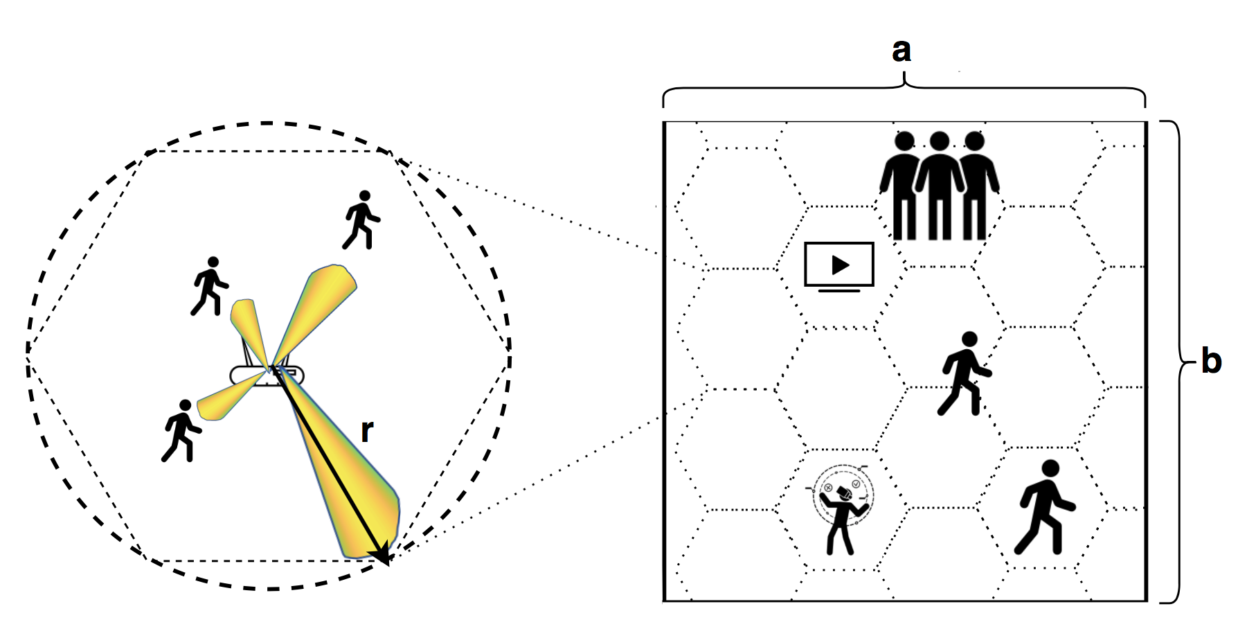
Let us consider a room of length and width with homogeneous distribution of different users. To ensure coverage the room has a blanket of THz-cells, a hexagonal cell, as shown in Fig 2. We envision the THz-AP is at the center of the THz-cell, which uses narrow beams to dynamically beam steer based on user position. Without loss of generality, the beam steering process resembles a circular shape of radius or the coverage area of the THz-cell. The maximum Euclidian separation between the TX-RX within a THz-cell can be .
II-B Optimal Number of APs
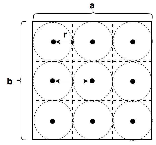
To find the optimal number of THz-APs for a room we constrain the maximum transmit power of the cell to , where is the total power for the room and is the optimal number of THz-APs. Let us consider a homogeneous room that is divided into cells each of length and width , as shown in Fig. 3(a). The total number of cells in the room is , where and are the number of cells on the x-axis and y-axis of the room respectively, where . Since each cell dimension is dependent on the assigned power, for each additional AP on the x-axis, the power for each cell will decrease and so will the radius . Thus, the variables and form a recursive relation to each other and is hard to solve in this form.
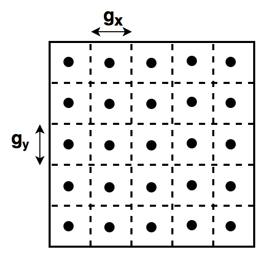
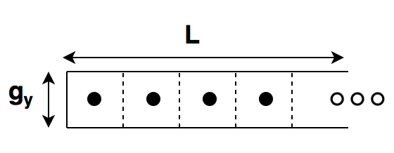
Let us dismantle the cell room and arrange it in a linear hypothetical room of length and width , as shown in Fig. 3(b). This hypothetical room constraints the width of the room . Without loss of generality we can derive the length of this hypothetical room as shown in Equation 3.
| (3) |
| (6) |
With simple manipulation on Equation 6 we have Equation 7, which is a function of and some constants, where and .
| (7) |
Equation 7 represents a widely studied form known as the Lambert’s function [17]. Using this inverse form we can solve as shown in Equation 8, where is the Lambert’s W-function given by the inverse of . Since fractional number of THz-AP doesn’t make sense, we use a ceiling function to round it off to the next integer value.
| (8) |
Thus, from Equation 8 we can figure out the optimal number of THz-APs required for a room such that each cell has a spectral efficiency of , a total power consumption of , and THz-cell radius as shown in Equation 9.
| (9) |
II-C Extension to a General Room
Now that we have optimal number of THz-APs for the hypothetical room, we would like to convert it back to its original rectangular room of size and . Since both the actual room and the hypothetical room have the same area, without loss of generality, we can show that the total number of cells is as shown in Equation 10.
| (10) |
Combining Equations 3 and 10 we can derive a relationship between the rectangular and hypothetical room, as shown in Equation 11.
| (11) |
Equation 11 highlights that all rectangular rooms of same area will require the same number of optimal THz-APs, i.e., if then .
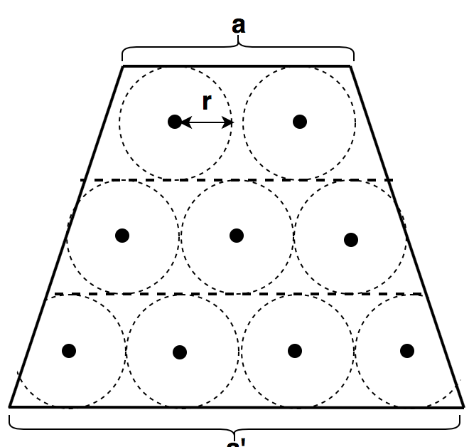
Equation 11 can be extended for any irregular room, like a trapezoid, which represents a conference or theater style room, or a polygonal room that can be converted to a rectangle, as shown in Fig. 4. Thus a trapezoid of lengths & and width is equivalent to a rectangle of length and width . The motivational example shown in Fig. 4 proves that for a square room of units, which requires THz-APs, can perfectly fit those same number of THz-APs into a trapezoid of lengths , units and width units. Please note due to our assumption of a THz-cell to be a circle, visually it seems that there are some white spaces; however, the hexagonal cell shape will perfectly fit without such white spaces.
Since from Equation 11 we can infer there exists multiple shapes and sizes of rooms that can fit the same number of THz-APs, for the rest of the paper we refer the size of a room as , which is equivalent to the hypothetical room.
II-D Heterogeneous Room Profile
So far, we have considered a homogeneous room, where each unit requires similar spectral efficiency. This assumption will yield high efficiency in the lower RF bands; however, in case of THz where the cell sizes are few meters in size and the demand is dependent on the user location, it will result in wastage of resources. To deploy THz-APs more efficiently, we need to understand that each square foot of the room is not the same. A regular room will have multiple pockets or hotspots, which have different users’ density and demands; thus, they should require a fewer number of THz-APs.
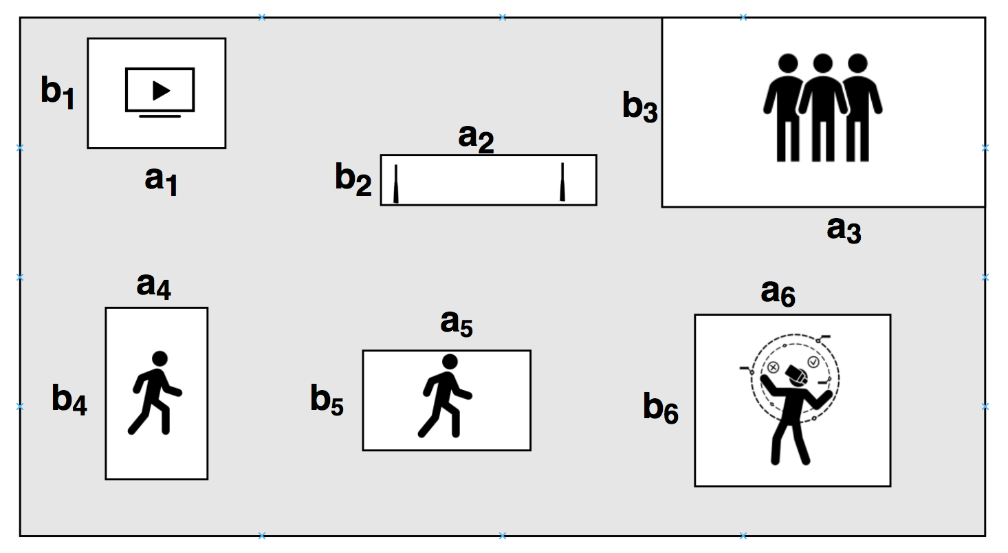
Based on the type of pocket, the pocket can be bounded by a smaller rectangular sub-room of size -by-. Please note, for simplicity, we draw rectangles; however, the pockets can also be represented using irregular shapes and then converted into a rectangle, as explained in Section II-C. Let us consider a room with six different types of demand pockets, as shown in Fig. 5. For static and point-to-point communication, the pocket size will be minimal and will bound the device area, as shown for pocket type and . However, in case of more number of users for pocket type , or users with varying mobility type on the y-axis , x-axis , or both axes for pocket types ,,and respectively, the size will be proportional to the user mobility, i.e., , [7]. By keeping the total power of the room constant, the power allocated for the pocket can be derived based on the number of users in that pocket, i.e., . After these pockets are identified each pocket can be considered homogeneous in itself and use Equation 9 to find the optimal number of THz-APs in each pocket, , where .
II-E Optimal Room Size
Although we have the optimal number of THz-APs for a room of size , it will also be interesting to bound the maximum room size for a fixed number of THz-APs. By simple mathematical manipulating of Equation 6 and combining constants, we get the Equation 12, where and .
| (12) |
With sufficient mathematical manipulation we can convert Equation 12 to represent the inverse Lambert function, as shown in Equation 15.
| (15) |
III Efficient Cell Packing Schemes
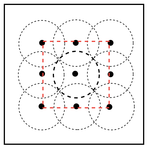
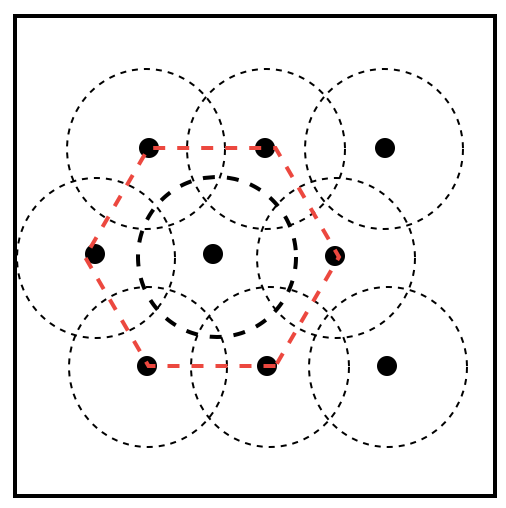
Outages due to blockages and environmental uncertainties can significantly impact the average throughput of the THz-APs within the demand pockets. To ensure minimum outages for mobile users during handoff, the THz-APs need to overlap with each other or have redundancies spatially. Moreover, As shown in Fig. 6, overlapping or packing of cells can lead to extra white spaces in the room, eventually increasing the total number of THz-APs. Even the way these THz-APs are packed in the room can affect the optimality analysis. For example, in Fig. 6 hexagonal packing is more efficient compared to square packing, which means hexagonal packing will require more THz-APs to offset the white space compared to square packing. In this section, we discuss two strategies of improving coverage while keeping the optimality analysis done in Section II constant.
III-A Radius Increase
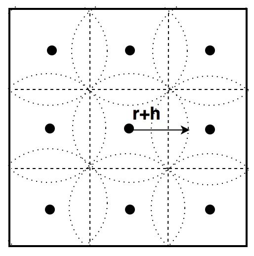
The first solution to avoid an increase in THz-APs is to increase the radius of the cells by just units over the optimal cell size of units, as shown in Fig. 7. By keeping the number of THz-APs fixed to , obtained from Equation 8, we can derive the new radius of the THz-cells that just overlaps units, as shown in Equation 17, where .
| (17) |
Using mathematical manipulation and Lambert function we can show that it represents the same form as Equation 12. Thus, solving for (using similar manipulation done for Equation 15), as shown in Equation 18, where and , and later deriving , as shown in Equation 19. If we keep operating frequency constant, the factor that can offset the increment is the parameter which is . We discuss the merits of this scheme in Section IV.
| (18) |
or,
| (19) |
III-B Repeater Assistance
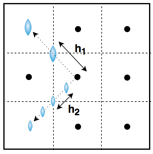
There are multiple caveats to the Radius Increase scheme, explained later in Section IV, which can be a nonviable solution for some parts of the THz spectrum (especially the upper end of the spectrum). Given our power and grid distribution constraints, these THz-cells can only operate till a distance , without any radius increase scheme, as explained in Section III-A, and the distance between two cells is . Thus, an alternative solution is to use repeaters, such as lenses, mirrors, reflectarrays, or hyper-surfaces [10], to reduce the distance between two THz-cells, eventually merging these two adjacent cells. As shown in Fig. 7(b), by using repeaters or relays, we can extend the coverage of a single cell to . However, the feasibility is dependent on the number of repeaters required for this cell merger strategy. As shown in Fig. 7(b), some THz frequencies might require two repeaters, while some might need an array of repeaters.
In this scheme, we replace the neighboring THz-AP, which is distance away, with number of repeaters along that path. Therefore, the new worst-case distance between two hops is , where is the number of repeaters. We assume that each repeater is equipped with a signal amplification, which can offset the attenuation of the signal during each hop. Moreover, when we combine two THz-APs, we will also combine the transmit power to and the required spectral efficiency to . Thus, for a fixed number of THz-APs , obtained from Equation 8, we can rewrite Equation 6 to Equation 20.
| (20) |
| (21) |
Using mathematical manipulation on Equation 21 we can solve for , the number of repeaters, as shown in Equation 21, where and .
| (22) |
IV Numerical Analysis
In this section, we perform an extensive analysis for the analytical models presented throughout the paper.
IV-A Simulation Parameters
The optimal value analysis shown in Sections II and III are dependent on a set of environmental and hardware factors. For our numerical analysis, we used the parameters mentioned in Table II, otherwise discussed separately in the text. Although the optimal values can be modeled for any type of room, in this paper, we limit our analysis to homogeneous user distribution, i.e., each cell requests the same spectral efficiency . We assume an average relative humidity of at a room temperature of . Although the sub-channels introduced in Table I have an abundance of contiguous bandwidth, to ensure spectral efficiency, we constrain the usable bandwidth to . THz spectrum will require very narrow beamwidth to offset the huge path losses. However, it was shown in [7] that there exists optimal antenna beamwidth based on user mobility, after which the average throughput will decline. We start our analysis with and then observe the change in optimal values for narrower antenna beamwidths [7].
| Parameter | Description | Value |
| Relative Humidity | ||
| Room Temperature | ||
| Room Transmit Power | ||
| Noise Spectral Density | ||
| Requested Data Rate | ||
| Available Bandwidth | ||
| Spectral Efficiency | ||
| Antenna Beamwidth | ||
| Hypothetical Room Length | ||
| THz-Cell Radius | () |
IV-B Evaluation of &
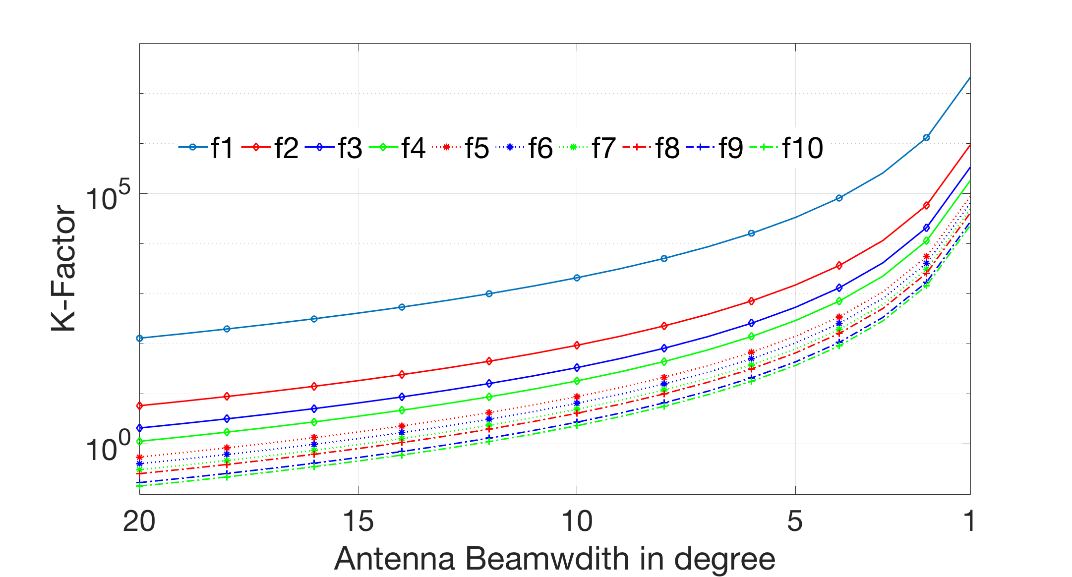
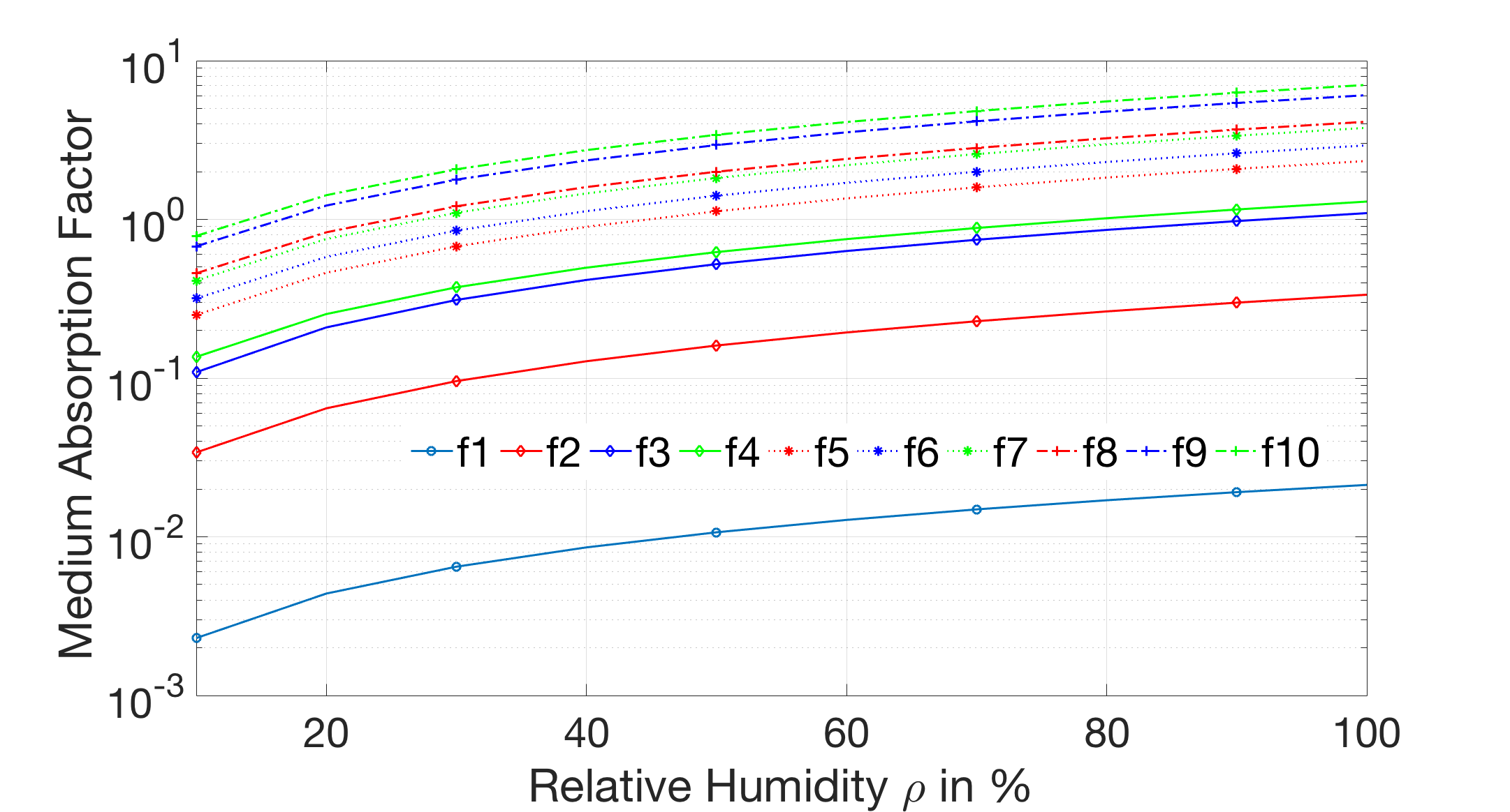
Before we compute the optimal values for a room, we need to explore more about the factors and , which exists in different forms throughout the analysis. If we keep frequency and other environmental parameters (like, room dimension, and relative humidity) constant, the variables through are predominantly dependent on the antenna gain (or the antenna beamwidth ). As shown in Fig. 8, the K-Factor value increases exponentially as we move closer to , which will result in fewer THz-APs. The -factor improvement is significant for lower frequency sub-channels, while the higher frequency sub-channels are indifferent to the beamwidth improvement. On the other hand, variables through the are dependent on medium absorption coefficient . Fig. 9 shows that the coefficient increases with increasing relative humidity, which results in higher path loss.
IV-C Optimal Number of APs
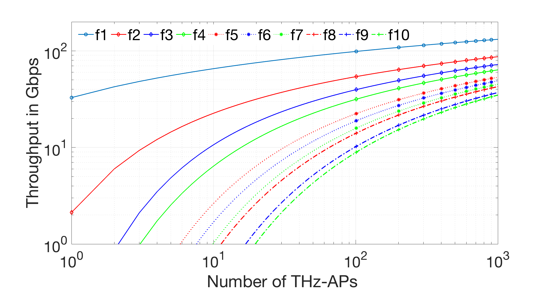
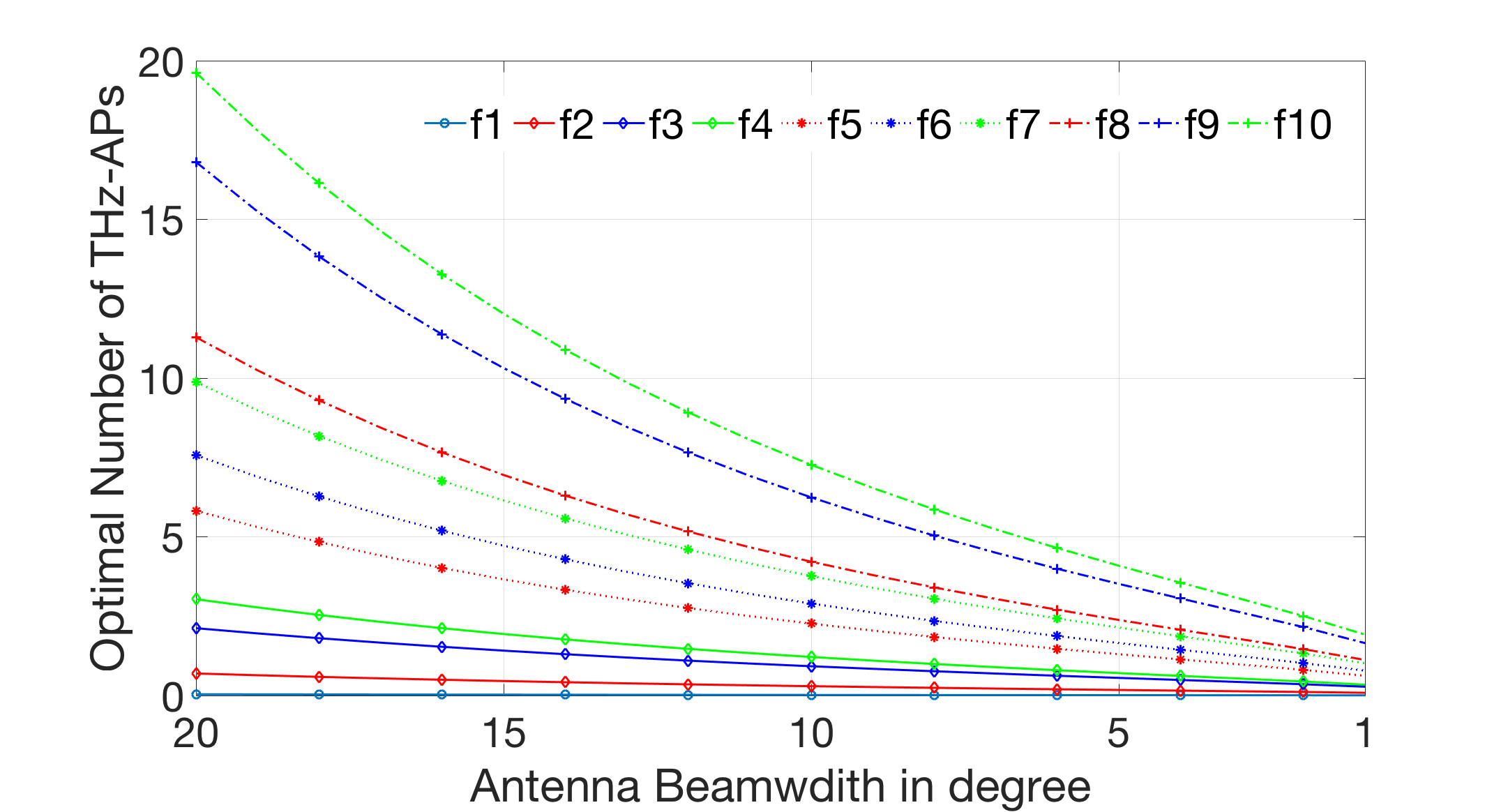
By using the parameter values in Table II with Equation 8, we can find the optimal number of THz-APs required for a room of at . Fig. 10 shows the optimal number of APs for different frequencies. Even with Thz-APs, none of the sub-channels except can achieve throughput. Moreover, due to the power constraint throughput for all of the sub-channels converge as the number of APs increase. If we compare these sub-channels on the spectral efficiency scale, shown in Table III, the higher sub-channels can reach for a much lower number of THz-APs if we use s of of contiguous bandwidth. If we want to use higher frequency sub-channels for high mobile users (i.e., pocket type , shown in Fig. 5) we will have to use large amount of bandwidth. On the contrary, for users with static or nomadic applications, we can use narrower beamwidth and reduce the number of THz-APs significantly, as shown in Fig. 11. The higher sub-channels require THz-APs to achieve a spectral efficiency of at .
IV-D Optimal Room Size
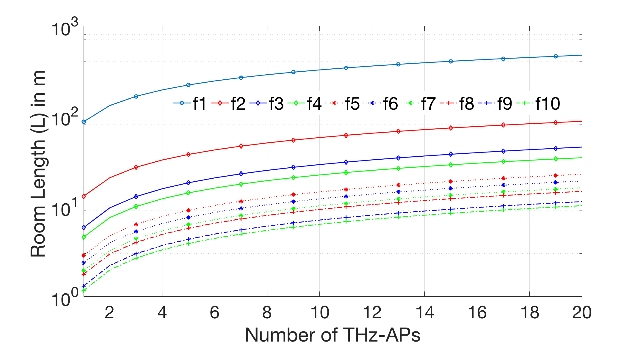
Fig. 12 shows the optimal room length for a fixed number of THz-APs. It seems that with a limited number of THz-APs, it is hard to achieve even a minimum spectral efficiency of . The optimal room lengths are very small for higher sub-channels. This relationship will help define the size of the demand pockets that can fit with a fixed amount of THz-APs in a room. For example, at higher sub-channels and relatively lower number of THz-APs, it is likely the pocket sizes will be smaller, resembling pocket types and , as shown in Fig 5. While for larger pocket sizes, the sub-channels through can efficiently be deployed with just APs.
IV-E Radius Increase
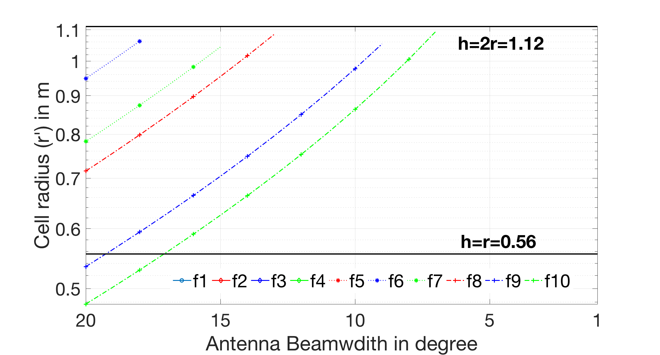
When we try to increase the radius of a THz-AP while keeping the frequency constant, we are effectively trying to figure out the improvement required in factor , which is . By improving the antenna gains (i.e., narrower beamwidths), we can effectively pack the cells while keeping the number of THz-APs constant. Although narrower antenna beamwidth can improve cell-packing, there is a limitation to this scheme. Firstly, antenna gains are dependent on the antenna beamwidth ; due to lack of sophisticated hardware in the THz, there is a physical limitation to the width of the beam. Secondly, as we keep on narrowing the beam, the beams are more susceptible to mobility induced outages [8]. Even small-scale mobility, such as head and body movement, can impact the connectivity [7].Thus there is both a physical and practical upper bound to the antenna gain we can achieve. Let us consider a fixed number of THz-APs , as shown in the motivational example in Fig. 4. The cell radius for varying antenna beamwidth is shown in Fig. 13, which is clipped off between at and , i.e., and from Equation 19. Sub-channels beyond show up in the clipped off version of Fig. 13, since the THz-APs, is more than what is required for the room, as shown in Table III.
IV-F Number of Repeaters
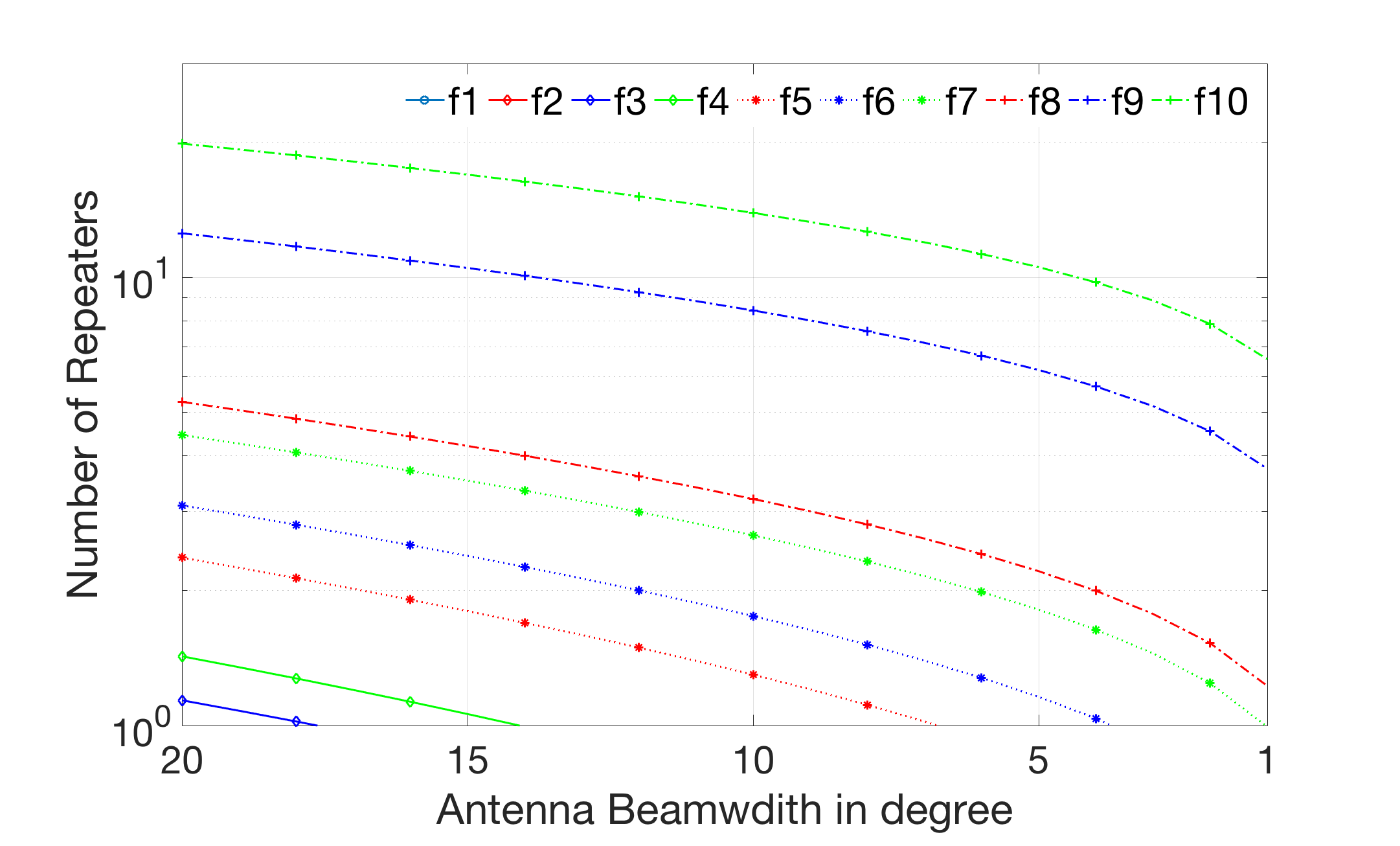
The radius increase strategy is a nonviable solution for mobile users in the higher sub-channels of the THz spectrum. Therefore, using repeaters and merging two adjacent THz-APs might be a viable solution for high speed mobility in higher sub-channels. Compared to Radius Increase method, which impact all adjacent neighbors, Repeater Assistance is targeted for a single neighboring cell. The number of repeaters required for varying antenna gain is shown in Fig. 14. In the case of the example shown in Fig. 4, the lower sub-channels and do not require any repeaters for cell merger. While for antenna beamwidth , the higher sub-channels will require multiple repeaters to merge two THz-cells. A combination of narrower antenna beamwidth and few repeaters might be a viable solution for mobile use at higher sub-channels.
V Conclusion
Given multiple challenges, indoor THz-APs are likely to be deployed more compactly with short-range and low-power transmitters. Narrower antenna beamwidth might help solve the issue; however, it will open up other problems such as small-scale mobility outages and the need for fast beam alignment strategy. In this paper, we present an analytical model to quantify: (a) the optimal number of THz-APs required for both homogeneous and heterogeneous user deployment, (b) optimal room length that can operate under a fixed number of THz-APs, (c) optimal cell radius increase required to improve cell packing, and (d) optimal number of the repeaters needed to merge two THz-APs. Our numerical analysis suggests that the higher sub-channels will require a significant amount of THz-APs to provide higher throughput compared to lower sub-channels. If we want to reduce the total number of THz-APs and still guarantee reliable communication, we might either need to improve gain or use repeaters or both. All of these methods will either increase outage time or increase deployment costs.The higher sub-channels are likely to be allocated for the static and nomadic indoor use-case, while the lower sub-channels are for relatively higher mobile use-cases. In the future, we would like to explore methods through which a room can be divided into smaller, more efficient demand pockets. Furthermore, special strategies can be implemented, specific to these pockets, to mitigate outages due to blockages and environmental uncertainties.
References
- [1] -“IMT traffic estimates for the years 2020 to 2030, M Series, Mobile, radiodetermination, amateur and related satellite services,” International Telecommunication Union Recommendation Sector (ITU-R), Tech.Rep. ITU-R M.2370-0, 2015.
- [2] I. F. Akyildiz, J. M. Jornet, and C. Han,“Terahertz band: Next frontier for wireless communications,” Physical Communication, vol. 12, pp. 16-32, 2014.
- [3] R. Singh, W. Lehr, D. Sicker, K. M. S. Huq, “Beyond 5G: The Role of THz Spectrum,” in Proc. of TPRC 47: The 47th Research Conference on Communication, Information and Internet Policy, 2019.
- [4] F. Lemic, et.al., “Survey on Terahertz Nanocommunication and Networking: A Top-Down Perspective,” arXiv:1909.05703[cs], Sep. 2019.
- [5] R. Singh, D. Sicker, “Reliable THz Communications for Outdoor based Applications- Use Cases and Methods,” in Proc. of IEEE Consumer Communications & Networking Conference (CCNC), 2020.
- [6] D. Correas-Serrano, J. S. Gomez-Diaz, “Graphene-based antennas for terahertz systems: A review,” arXiv:1704.00371, Apr. 2017.
- [7] R. Singh, D. Sicker, “Parameter Modeling for Small-Scale Mobility in Indoor THz Communication,” in Proc. of IEEE Global Communications Conference (GLOBECOM), 2019.
- [8] R. Singh, D. Sicker, K. M. S. Huq, “MOTH- Mobility-induced Outages in THz: A Beyond 5G (B5G) application,” in Proc. of IEEE Consumer Communications & Networking Conference (CCNC), 2020.
- [9] A. A. Boulogeorgos ; E. N. Papasotiriou ; A. Alexiou, “A Distance and Bandwidth Dependent Adaptive Modulation Scheme for THz Communications,” in Proc. of IEEE 19th International Workshop on Signal Processing Advances in Wireless Communications (SPAWC), Jun. 2018.
- [10] I. F. Akyildiz, C. Han, and S. Nie, “Combating the distance problem in the millimeter wave and terahertz frequency bands,” IEEE Communications Magazine, vol. 56, no. 6, pp. 102-108, 2018.
- [11] S. Mohrehkesh and M. C. Weigle, “Optimizing energy consumption in terahertz band nanonetworks,” IEEE J. Sel. Areas Commun., vol. 32, no. 12, pp. 2432-2441, Dec. 2014.
- [12] C. Lin and G. Y. Li, “Energy-efficient design of indoor mmwave and sub-THz systems with antenna arrays,” IEEE Trans. Wireless Commun., vol. 15, no. 7, pp. 4660-4672, Jul. 2016.
- [13] V. Petrov, D. Moltchanov, and Y. Koucheryavy, “On the efficiency of spatial channel reuse in ultra-dense thz networks,” in IEEE Global Communications Conference (GLOBECOM), pp. 1-7, Dec 2015.
- [14] C. Lin, G. Y. Li, “Indoor Terahertz Communications: How Many Antenna Arrays Are Needed?” IEEE Transaction on Wireless Comm., vol. 14, no. 6, 2015.
- [15] V. Petrov, D. Moltchanov, Y. Koucheryavy, “Applicability assessment of terahertz information showers for next-generation wireless networks,” in IEEE International Conference on Communications (ICC), May 2016. DOI: 10.1109/ICC.2016.7511129
- [16] V. Petrov, et.al., “Last Meter Indoor Terahertz Wireless Access: Performance Insights and Implementation Roadmap,” IEEE Communications Magazine, vol. 56, no. 6, Jun. 2018.
- [17] E. W. Weisstein. “Lambert W-Function.” Available [Online]: http://mathworld.wolfram.com/LambertW-Function.html
- [18] J. M. Jornet, I. F. Akyildiz, “Channel Modeling and Capacity Analysis for Electromagnetic Wireless Nanonetworks in the Terahertz Band,” IEEE Transactions on Wireless Communications, vol. 10, no. 10, pp. 3211-3221, Oct. 2011. DOI: 10.1109/TWC.2011.081011.100545