Multimode interference induced optical nonreciprocity and routing in an optical microcavity
Abstract
Optical nonreciprocity and routing using optocal microcavities draw much atttention in recent years. Here, we report the results of the study on the nonreciprocity and routing using optomechanical multimode interference in an optical microcavity. The optomechanical system used here possesses multi-optical modes and a mechanical mode. Optomechanical induced transparency and absorption, appear in the system due to the interference between different paths. The system can present significant nonreciprocity and routing properties when appropriate parameters of the system are set. We design quantum devices, such as diode, circulator and router, which are important applications. Our work shows that optomechanical multimode system can be used as a promising platform for buliding photonic and quantum network.
I Introduction
High quality optical microcavities vahala2003optical , which can enhance light–matter interactions in a very confined volume, play an essential role in optical physics study and applications. Examples of such applications include parity-time-symmetry peng2014parity ; jing2014pt ; chang2014parity , chaos jiang2017chaos ; lu2015p , microcavity sensors sensing ; chen2017exceptional ; zhang2017far ; ward2018nanoparticle ; qin2019brillouin ; wang2018rapid , and etc. As a promising platform for realizing quantum electrodynamics, cavity optomechanics in optical microcavity have been widely investigated theoretically and experimentally aspelmeyer2014cavity ; probing ; arcizet2006radiation ; Qin:20 . Early studies are restricted to basic optomechanical models with one optical mode and one mechanical mode, models with multimode interaction, which couples multiple optical modes to a mechanical mode, exhibit richer physics phenomena such as optomechanical induced transparency (OMIT) weis2010optomechanically ; kronwald2013optomechanically ; safavi2011electromagnetically ; kim2015non ; lu2018optomechanically ; dong2012optomechanical ; Long1 ; Long2 and absorption (OMIA) PhysRevA.71.043804 ; qu2013phonon and shows enormous potential in applications ranging from quantum information processing to state transfers kuzyk2017controlling ; liao2016macroscopic ; liu2013dynamic ; stannigel2012optomechanical ; zhang2019fast ; liu2019sensing ; wang2019chemo ; chen2019phononic ; liu2018optothermal ; wang2012generation ; wang2012quantum ; wei2015hybrid ; wang2020entanglement ; wang2012using ; tian2012adiabatic ; xu2019frequency .
In recent years, as an intriguing physical phenomena, optical nonreciprocity has attracted great attentain, especially for nonreciprocity devices, which are widely used in diodes or isolators, the fundamental buliding-blocks of information network. Traditionally, optical nonreciprocity is associated with Faraday rotation effect Faraday by breaking the time-reversal symmetry. Besides, nonmagnetic optical nonreciprocity, including nonlinear optics fan2012all , optoacoustic effects kang2011reconfigurable and parity-time-symmetric structures ruter2010observation , can also be achieved. Optomechanical systems provide a promising platform for studying nonreciprocity dong2015brillouin ; miri2017optical ; manipatruni2009optical ; bernier2017nonreciprocal ; gui2006general ; long2018realistic ; qin2019proposal induced by optomechanical multimode interference. Using this system, optical isolators shen2016experimental ; ruesink2016nonreciprocity , circulators ruesink2018optical ; xu2015optical , and directional amplifiers shen2018reconfigurable have been theoretically studied and experimentally realized. Optical router is another key element for controlling the path of signal flow in quantum and classical network, it can be also constructed through muiltimode interference. Recently, quantum router has been proposed in various systems, i.e., cavity atom zhou2013quantum ; shomroni2014all ; yan2018targeted ; li2015designable ; lu2014single ; aoki2009efficient ; hoi2011demonstration ; chen2013all ; miller2010optical , coupled resonator xia2013all and optomechanical systems agarwal2012optomechanical ; fang2016optical .
In this paper, we propose a scheme to realize controllable optical nonreciprocity and routing based on multimode interference in an optical cavity. The multimode system in our proposal is realized by coupling multi optical modes with a mechanical mode in an optical cavity. The multi optical modes are composed of a pair of coupled clockwise (CW) and counter-clockwise (CCW) modes. Fundamental physical phenomena, such as OMIT and OMIA can induced in the system. When signal input upon port 1 and port 2, which are in opposite directions, our system exhibits tunable nonreciprocity and the isolation ratio can be controlled by adjusting the optomechanical coupling strength. With this property, basic devices such as opitcal diodes and circulators can be designed. For transmission spectrum on three or four ports, the system presents controllable routing properties, which can be used for building quantum router. The result shows that photon can be transferred from the input port to an arbitrarily selected output port with nearly 100 transmission.
This article is organized as follows: We describe the basic model of multimode interactions in optical microcavities in Sec.II. In Sec.IIIA, we study the multimode interference, and we show how to realize the tunable nonreciprocity and circulator in Sec.III.2. Three-port and four-port routing schme are given in Sec.IV.1 and B, respectively. Conclusion is given in Sec.V.
II Basic model of multimode interaction
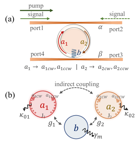
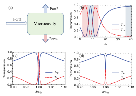
We consider a four-port optomechanical system shown in Fig. 1 (a), where a microcavity resonator is coupled with two fibers and through evanescent field simultaneously. Two cavity modes and , with corresponding frequencies and , are coupled to the same mechanical mode with frequencies via radiation pressure. In addition, the whispering-gallery modes and couple indirectly through the fiber. Both the optical modes and support a pair of CW and CCW modes with oppsite travelling directions and with coupling strength and , as shown in Fig. 1 (b). By pumping a laser field with frequency and amplitude from port 1, which excites the coupling between the mechanical mode and the CW optical field in the cavity, the Hamiltonian of the system is given by ()
| (1) |
The first term in the right hand
| (2) |
describes the free Hamiltonian of each mode of the system, where () denotes the annihilation (creation) operators of -th CW and CCW modes, respectively, and () is the annihilation (creation) operator of the mechanical mode. The second term
| (3) |
denotes the multimode interaction. The first term of represents the interactions between the cavity and mechanical mode, and the second one describes the coupling between the CW and CCW mode. is the single-photon optomechanical coupling rate. And is the photon-hopping strength between the CW and CCW mode due to optical backscattering. The third term
| (4) |
represents the Hamiltonian of the and waveguide mode, the coupling between the optical modes and two waveguide modes, respectively. The annihilation operator () denotes the waveguide mode with commutation relation . Parameter is the external loss rate between the cavity mode and the fiber and . The last term
| (5) |
describes the pump field. When a probe laser, with amplitude and frequency , is input into the system from port ( 1,2,3,4), considering dissipation and quantum (thermal) noise, the quantum Langevin equations for the operators in the rotating frame of the pump fields are given by
| (6) | ||||
| (7) | ||||
| (8) |
where the coefficients and are
| (9) | |||
| (10) |
represents the interaction between optical mode and waveguide and , and = denotes the detuning between the driving field and the cavity mode. is the total loss rate which contains an intrinsic loss rate and external loss rate and is the detuning between the probe field and the pump field. Using standard linearization, the steady-state solution of the Eq. (6) - (8) in the red detuning can be obtained as follows:
| (11) |
| (12) |
| (13) |
| (14) |
where the coefficients are
According to the input-output relation wallsquantum , one can obtain the transmission spectrum of different ports.
III Multimode interference and Optical nonreciprocity
III.1 OMIT and OMIA in multimode interference
.
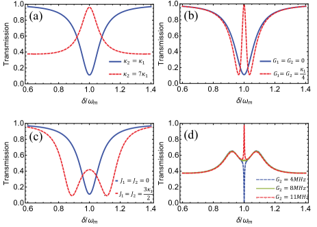
In our system, there are several ways of interference: (1) the interference of the optical modes and , which couples indirectly through the waveguide, can induce EIT-like line shape plotted with orange dashed line in Fig. 2 (a), which was found in Ref.totsuka2007slow ; xu2006experimental ; xiao2009electromagnetically , while in a waveguide-coupled microcavity system, the transmission spectrum is usually featured by symmetrical Lorentzian line shape as shown with the blue solid line. (2) the CW mode couples with the mechanical mode by driving the pump field from CW direction. With changing the effective optomechanical coupling rate, we can always find the OMIT phenomenon in Fig. 2 (b), which was studied in Ref.aspelmeyer2014cavity . (3) the direct coupling of CW and CCW modes from each optical mode is another interference, resulting in mode-splitting by adjusting the photon-hopping interaction as shown in Fig. 2 (c), and the interference between the CW and CCW modes was studied in Ref.mazzei2007controlled . When all the interferences co-exist, the transmission becomes more complicated and we show the results in Fig. 2 (d). With basic EIT-like shape, we consider the photon-hopping interaction , and adjust the optomechanical coupling rate, the transmission spectrum shows OMIT (red dashed line) and OMIA (blue dashed line) phenomenon. The transmission rate can be controlled by choosing appropriate parameters. The parameters of red dashed line in Fig. 2 (a) and (d) are 2 MHz, 100 MHz, 200 MHz, 500 MHz, 1 MHz. The parameters of red dashed line in Fig. 2 (b) and (c) are 10 MHz, 1 MHz. And the parameters of blue solid line in Fig. 2 (a),(b) and (c) are 10 MHz, 1 MHz, = 0, 0. Other figures are given in the caption.
III.2 Optical nonreciprocity and circulator
Firstly, we study the case of weak interaction between CW and CCW mode where coupling strength is small, the and of the Eq. (11) - (14) can be omitted. We investigate the transmission between port 1 and port 2. According to the input-output relation
| (15) |
and we denote as the transmission from port to port . When the signal field is input on port 1 (i.e. 0), the transmission coefficient is
| (16) |
If the signal field is input on port 2 (i.e. 0), the transmission coefficient is
| (17) |
Substituting Eq. (11) - (14) into the transmission rate, one can rewrite the coefficients as
| (18) |
| (19) |
The corresponding power transmission coefficient is given by and .
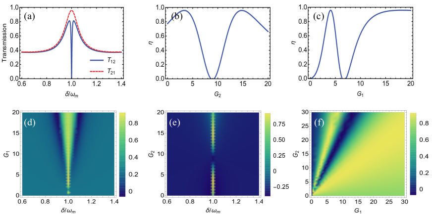
We calculate the power transmission coefficient and versus which is shown in Fig. 3 (a). When the detuning , transmission rate is 0, but the oppsite one is 1. It shows that the nonreciprocal optical transimission is enabled, where the signal can be transmit from port 2 to port 1, but the inverse process is forbidden. We define isolation coefficient to measure the degree of the nonreciprocity. Because the transmission is sensitive to the optomechanical coupling strength, we plot in Fig. 3 the as a function of and respectively at detuning , from which 1 for some values of and , at which the nonreciprocal phenomenon is available. Fig. 3 (d) shows the isolation coefficient versus and , in which high isolation rate can be achieved at with the increase of . Similarly, by adjusting , one can observe that the value of decrease when satisfies 3 MHz 9 MHz and increase when is 9 MHz 15 MHz. reaches its maximum value at the point of 5 MHz and 19 MHz as shown in Fig. 3 (e). The effect of and on is asymmetric due to the difference of the loss rate of optical mode and . Fig. 3 (f) illustrates how the isolation rate depends on and , from which one can find that with the change of and , the high isolation rate occupies a large proportion. The perfect nonreciprocity can be achieved by setting optical parameters. The physical mechanism of this phenomenon can be understood easily. Under the weak coupling of CW mode and CCW mode, there are two main types of interference involved in this system, i.e. indirectly coupling of the two optical modes and optomechanically coupling between CW mode and mechanical mode. Only CCW mode without optomechanically coupling is included in the transmission rate , which always results in EIT-like line shape. For transmission rate , it contains two interference paths mentioned above and induces both OMIT and OMIA as shown in Fig. 2 (d).
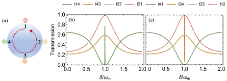
Considering the situation of all four ports, because of the directional pump field, the coupling of CW mode and mechanic mode result in nonreciprocity, the transmission in port 1,2 is symmetric with that in port 3,4. When signal field input from port 1 (3), the time-reversal symmetry is broken and the system exhibits nonreciprocity. While signal field input from port 2 (4), the system functions as an add-drop filter. We define as the signal transmission from the -th to the -th port and the reversal for 1,2,3,4. In Fig. 4 (b), is plotted as a function of detuning , with relatively high transmission rate. And the transmission of opposite direction is near-zero as shown in Fig. 4 (c). It means the signal is transferred from one port to the adjacent port in a CCW direction (), but CW is forbidden as shown in Fig. 4 (a), which functions as a circulator.
IV Optical routing
IV.1 Three-port routing
Now we consider the signal field input from port 1, and calculate the transmission spectrum at port 2,3 and 4. The definition of is the same as before, and
| (20) |
| (21) |
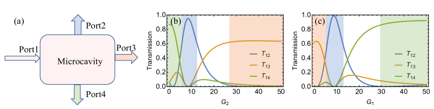
We plot the numerical results in Fig. 5 to show the possibility of routing implementation. For comparison, we first assume 0, indicating no scatting interaction. Output field from port 3 is absent in this case. The signal field input from port 1 can only output from port 2 and port 4 as shown in Fig. 5 (a). Fig. 5(b) shows the transmission rate from port 2 and port 4 as a function of optomechanical rate , from which we find that the output field of the two ports can achieve almost perfect routing. When MHz, the tranmission rates are and respectively, that is, the signal only outputs from port 2. With the increase of , the signal strength of the two ports starts to convert including a balanced 50:50 beam splitter. When is increased to 8 MHz, the signal only outputs from port 4. We plot in Fig. 5 (c)-(d) the transmission rate versus the detuning with MHz, 10 MHz, corresponding to a 100:0 and a 50:50 splitting rate, respectively. It can be shown that the three-port router can operate at any splitting ratio ranging from 0:100 to 100:0 with appropriate optomechanical coupling strength.
IV.2 Four-port routing
When is large, the scattering effect is present, all three pathways are involved in the interference. The output field begins to appear on port 3. We show in Fig. 6 how to route a photon in a deterministic way, i.e., photon inputs from port 1 can be routed to one of other three ports deterministically as shown in Fig. 6 (a). Without loss of generality, we study the transmission rate at the point of detuning . Since the system is sensitive to the optomechanical coupling strength, two different routing schemes are obtained by adjusting and respectively. In the first set of parameters, is adjusted as shown in Fig. 6 (b), it can be seen that and can be almost suppressed while can be up to 90 around = 2 MHz. And if increases to 8 MHz,the signal can be routed to port 2 completely with efficiency close to 100. With the continued increase of , port 2 and port 4 have almost no output, while port 3 has a nearly constant transmission rate of 0.6. Here, the transmission rate can not reach 1, mainly because that the scattered light is the main component of port 3, photon is lost in the cavity or output from port 1. Different color region corresponds to different output ports in Fig. 6 (b). It means, for an incident photon, target photon routing can be achieved deterministically by setting appropriate values of . Under another set of parameters, we can achieve a similar function by adjusting , except that the output ports are different when the optomechanical coupling coefficient is gradually increased as shown in Fig. 6 (d). In this way, the multimode optomechanical system can be used as a controllable quantum router which the photon can emit from the desired target port with relatively high efficiency, which is attributed to the interference between different phonon excitation paths.
V Conclusion
In summary, we investigated the optomechanical multimode system that can be used to realize controllable optical nonreciprocity and routing, which is due to the multimode interference between different paths. We demonstrated that the nonreciprocal response is enabled when signal is input from opposite ports and nonreciprocity with high isolation can be realized by tuning the optomechanical coupling rates. Optical device such as diodes and isolators are possible because of the nonreciprocal phenomenon. We also showed that the system can also be used as photon routing with three or four ports, in which photon can be transferred from the input port to an arbitrarily target output port with high transmission.
ACKNOWLEDGMENT
The work was supported by the National Natural Science Foundation of China under Grants (11974205); National Key Research and Development Program of China (2017YFA0303700); Beijing Advanced Innovation Center for Future Chip (ICFC); The Key Research and Development Program of Guangdong province (2018B030325002). H.Z. acknowledges the China Postdoctoral Science Foundation under Grant No.2019M650620. M.W. acknowledges the China Postdoctoral Science Foundation under Grant No.2019M660605
References
- (1) K. J. Vahala, Optical microcavities, Nature (London) 424, 839 (2003).
- (2) B. Peng, S. K. Özdemir, F. Lei, F. Monifi, M. Gianfreda, G. L. Long, S. Fan, F. Nori, C. M Bender, and L. Yang, Parity–time-symmetric whispering-gallery microcavities, Nat. Phys. 10, 394 (2014).
- (3) H. Jing, S. K. Özdemir, X.-Y. Lü, J. Zhang, L. Yang, and F. Nori, PT-symmetric phonon laser, Phys. Rev. Lett. 113, 053604 (2014).
- (4) L. Chang, X. Jiang, S. Hua, C. Yang, J. Wen, L. Jiang, G. Li, G. Wang, and M. Xiao, Parity–time symmetry and variable optical isolation in active–passive-coupled microresonators Nat. photonics 8, 524 (2014).
- (5) X. Jiang, L. Shao, S.-X. Zhang, X. Yi, J. Wiersig, L. Wang, Q. Gong, M. Lončar, L. Yang, and Y.-F. Xiao, Chaos-assisted broadband momentum transformation in optical microresonators, Science 358, 344-347 (2017).
- (6) X.-Y. Lü, H. Jing, J. Y. Ma, and Y. Wu, PT-Symmetry-Breaking Chaos in Optomechanics, Phys. Rev. Lett. 114, 253601 (2015).
- (7) C. L. Degen, F. Reinhard, and P. Cappellaro, Quantum sensing, Rev. Mod. Phys. 89, 035002 (2017).
- (8) W. Chen, S. K. Özdemir, G. Zhao, J. Wiersig, and L. Yang, Exceptional points enhance sensing in an optical microcavity, Nature (London) 548, 192 (2017).
- (9) N. Zhang, Z. Gu, S. Liu, Y. Wang, S. Wang, Z. Duan, W. Sun, Y.-F. Xiao, S. Xiao, and Q. Song, Far-field single nanoparticle detection and sizing, Optica 4, 1151 (2018).
- (10) J. M. Ward, Y. Yang, F. Lei, X.-C. Yu, Y.-F. Xiao, and S. N. Chormaic, Nanoparticle sensing beyond evanescent field interaction with a quasi-droplet microcavity, Optica 5, 674 (2018).
- (11) G.-Q. Qin, M. Wang, J.-W. Wen, D. Ruan, and G. L. Long, Brillouin cavity optomechanics sensing with enhanced dynamical backaction, Photon. Res. 7, 1440 (2019).
- (12) T. Wang, X. F. Liu, Y. Q. Hu, G. Q. Guo, D. Ruan and G. L. Long, Rapid and high precision measurement of opto-thermal relaxation with pump-probe method, Science. Bulletin. 63, 287 (2018).
- (13) M. Aspelmeyer, T. J. Kippenberg, and F. Marquardt, Cavity optomechanics, Rev. Mod. Phys. 86, 1391 (2014).
- (14) I. Pikovski, M. R. Vanner, M. Aspelmeyer, M. S. Kim and Č. Brukner, Probing planck-scale physics with quantum optics, Nat. Phys. 8, 393 (2012).
- (15) O. Arcizet, P.-F. Cohadon, T. Briant, M. Pinard and A. Heidmann, Radiation-pressure cooling and optomechanical instability of a micromirror, Nature. 444, 71 (2006).
- (16) G.-Q. Qin, H. Yang, X. Mao, J.-W Wen, M. Wang, D. Ruan and G. L. Long, Manipulation of optomechanically induced transparency and absorption by indirectly coupling to an auxiliary cavity mode, Opt. Express. 28, 580–592 (2020).
- (17) S. Weis, R. Rivière, S. Deléglise, E. Gavartin, O. Arcizet, A. Schliesser and T. J. Kippenberg, Optomechanically induced transparency, Science. 330, 1520 (2010).
- (18) A. Kronwald and F. Marquardt, Optomechanically induced transparency in the nonlinear quantum regime, Phys. Rev. Lett. 111, 133601 (2013).
- (19) A. H. Safavi-Naeini, T. M. Alegre, J. Chan, M. Eichenfield, M. Winger, Q. Lin, J. T. Hill, D. E. Chang and O. Painter, Electromagnetically induced transparency and slow light with optomechanics, Nature (London) 472, 69 (2011).
- (20) J. Kim, M. C. Kuzyk, K. Han, H. Wang, and G. Bahl, Non-reciprocal Brillouin scattering induced transparency, Nat. Phys. 11, 275 (2015).
- (21) H. Lü, C. Wang, L. Yang and H. Jing, Optomechanically induced transparency at exceptional points, Phys. Rev. Appl. 10, 014006 (2018).
- (22) C. Dong, V. Fiore, M. C. Kuzyk and H. Wang, Optomechanical dark mode, Science. 338, 1609–1613 (2012).
- (23) F. C. Lei, M. Gao, C. G. Du, Q. L. Jing, and G. L. Long, Three-pathway electromagnetically induced transparency in coupled-cavity optomechanical system, Opt. Express 23, 11508–11517 (2015).
- (24) T. Wang, Y.-Q. Hu, C.-G. Du and G. L. Long, Multiple EIT and EIA in optical microresonators, Opt. Express 27, 7344-7353 (2019).
- (25) A. Naweed, G. Farca, S. I. Shopova and A. T. Rosenberger, Induced transparency and absorption in coupled whispering-gallery microresonators, Phys. Rev. A. 71, 043804 (2005).
- (26) K. Qu and G. S. Agarwal, Phonon-mediated electromagnetically induced absorption in hybrid opto-electromechanical systems, Phys. Rev. A. 87, 031802 (2013).
- (27) M. C. Kuzyk and H. Wang, Controlling multimode optomechanical interactions via interference, Phys. Rev. A. 96, 023860 (2017).
- (28) J.-Q. Liao and L. Tian, Macroscopic quantum superposition in cavity optomechanics, Phys. Rev. Lett. 116, 163602 (2016).
- (29) Y.-C. Liu, Y.-F. Xiao, X. Luan, and C. W. Wong, Dynamic Dissipative Cooling of a Mechanical Resonator in Strong Coupling Optomechanics, Phys. Rev. Lett. 110, 153606 (2013).
- (30) K. Stannigel, P. Komar, S. J. M. Habraken, S. D. Bennett, M. D. Lukin, P. Zoller and P. Rabl, Optomechanical quantum information processing with photons and phonons, Phys. Rev. Lett. 109, 013603 (2012).
- (31) S.-S. Chen, H. Zhang, Q. Ai and G.-J. Yang, Phononic entanglement concentration via optomechanical interactions, Phys. Rev. A 100, 052306 (2019).
- (32) X.-F. Liu, T.-J. Wang, and C. Wang, Optothermal control of gains in erbium-doped whispering-gallery microresonators, Opt. Lett. 43, 326-329 (2018).
- (33) H. Zhang, X.-K. Song, Q. Ai, H. Wang, G.-J. Yang, and F.-G. Deng, Fast and robust quantum control for multimode interactions using shortcuts to adiabaticity, Opt. Express 27, 7384 (2019).
- (34) D. E. Liu, Sensing Kondo correlations in a suspended carbon nanotube mechanical resonator with spin-orbit coupling, Quantum Engineering. 1, e10 (2019)
- (35) M. Wang, R. Wu, J. Lin, J. Zhang, Z. Fang, Z. Chai, and Y. Cheng, Chemo-mechanical polish lithography: A pathway to low loss large-scale photonic integration on lithium niobate on insulator, Quantum Engineering. 1, e9 (2019)
- (36) T.-J. Wang, Y. Lu and G. L. Long, Generation and complete analysis of the hyperentangled Bell state for photons assisted by quantum-dot spins in optical microcavities, Phys. Rev. A. 86, 042337 (2012).
- (37) T.-J. Wang, S. Y. Song and G. L. Long, Quantum repeater based on spatial entanglement of photons and quantum-dot spins in optical microcavities, Phys. Rev. A. 85, 062311 (2012).
- (38) H.-R. Wei and G. L. Long, Hybrid quantum gates between flying photon and diamond nitrogen-vacancy centers assisted by optical microcavities, Scientific. Reports. 5, 12918 (2015).
- (39) G. Y. Wang and G. L. Long, Entanglement purification for memory nodes in a quantum network, SCIENCE CHINA Physics, Mech. & Astron. 63, 220311 (2020)
- (40) Y. D. Wang and A. A. Clerk, Using interference for high fidelity quantum state transfer in optomechanics, Phys. Rev. Lett. 108, 153603 (2012).
- (41) L. Tian, Adiabatic state conversion and pulse transmission in optomechanical systems, Phys. Rev. Lett. 108, 153604 (2012).
- (42) X.-S. Xu, H. Zhang, X.-Y. Kong, M. Wang and G. L. Long, Frequency-tuning induced state transfer in optical microcavities, arXiv:1912.00571 (2019), to appear in Photonics Research.
- (43) F. D. M. Haldane and S. Raghu, Possible Realization of Directional Optical Waveguides in Photonic Crystals with Broken Time-Reversal Symmetry, Phys. Rev. Lett. 100, 013904 (2008).
- (44) L. Fan, J. Wang, L. T. Varghese, H. Shen, B. Niu, Y. Xuan, A. M. Weiner and M. Qi, An all-silicon passive optical diode, Science. 335, 447 (2012).
- (45) M. S. Kang, A. Butsch, and P. S. J. Russell, Reconfigurable light-driven opto-acoustic isolators in photonic crystal fibre, Nat. Photonics. 5, 549 (2011).
- (46) C. E. Rüter, K. G. Makris, R. EI-Ganainy, D. N. Christodoulides, M. Segev, and D. Kip, Observation of parity–time symmetry in optics, Nat. Phys. 6, 192 (2010).
- (47) C.-H. Dong, Z. Shen, C.-L. Zou, Y.-L. Zhang, W. Fu, and G.-C. Guo, Brillouin-scattering-induced transparency and non-reciprocal light storage, Nat. Commun. 6, 6193 (2015).
- (48) M.-A. Miri, F. Ruesink, E. Verhagen and A. Alù, Optical nonreciprocity based on optomechanical couplings, Phys. Rev. Appl. 7, 064014 (2017).
- (49) S. Manipatruni, J. T. Robinson and M. Lipson, Optical nonreciprocity in optomechanical structures, Phys. Rev. Lett. 102, 213903 (2009).
- (50) N. R. Bernier, L. D. Toth, A. Koottandavida, M. A. Ioannou, D. Malz, A. Nunnenkamp, A. K. Feofanov and T. J. Kippenberg, Nonreciprocal reconfigurable microwave optomechanical circuit, Nat. Commun. 8, 13662 (2017)
- (51) G. L. Long, General quantum interference principle and duality computer, Communications in Theoretical Physics. 45, 825 (2006)
- (52) G. L. Long, W. Qin, Z. Yang and J.-L. Li, Realistic interpretation of quantum mechanics and encounter-delayed-choice experiment, SCIENCE CHINA Physics, Mech. & Astron. 61, 030311 (2018)
- (53) W. Qin, A. Miranowicz, G. L. Long, J. Q. You and F. Nori, Proposal to test quantum wave-particle superposition on massive mechanical resonators, npj Quantum Information. 5, 1-8 (2019)
- (54) Z. Shen, Y.-L. Zhang, Y. Chen, C.-L. Zou, Y.-F. Xiao, X.-B. Zou, F.-W. Sun, G.-C. Guo, and C.-H. Dong, Experimental realization of optomechanically induced non-reciprocity, Nat. Photonics 10, 657 (2016).
- (55) F. Ruesink, M.-A. Miri, A. Alù and E. Verhagen, Nonreciprocity and magnetic-free isolation based on optomechanical interactions, Nat. Commun. 7, 13662 (2016)
- (56) F. Ruesink, J. P. Mathew, M.-A. Miri, A. Alù and E.Verhagen, Optical nonreciprocity and optomechanical circulator in three-mode optomechanical systems, Nat. Commun. 9, 1798 (2018).
- (57) X.-W. Xu and Y. Li, Optical nonreciprocity and optomechanical circulator in three-mode optomechanical systems, Phys. Rev. A. 91, 053854 (2015).
- (58) Z. Shen, Y.-L. Zhang, Y. Chen, F.-W. Sun, X.-B. Guo and C.-H. Dong, Reconfigurable optomechanical circulator and directional amplifier, Nat. Commun. 9, 1797 (2018).
- (59) L. Zhou, L.-P. Yang, Y. Li and C. P. Sun, Quantum routing of single photons with a cyclic three-level system, Phys. Rev. Lett. 111, 103604 (2013)
- (60) I. Shomroni, S. Rosenblum, Y. Lovsky, O. Bechler, G. Guendelman and B. Dayan, All-optical routing of single photons by a one-atom switch controlled by a single photon, Science 345, 903 (2014).
- (61) C.-H. Yan, Y. Li, H. Yuan, and L. F. Wei, Targeted photonic routers with chiral photon-atom interactions, Phys. Rev. A. 97, 023821 (2018)
- (62) X. Li and L. F. Wei, Designable single-photon quantum routings with atomic mirrors, Phys. Rev. A. 92, 063836 (2015)
- (63) J. Lu, L. Zhou, L.-M. Kuang and F. Nori Single-photon router: Coherent control of multichannel scattering for single photons with quantum interferences, Phys. Rev. A. 89, 013805 (2014)
- (64) T. Aoki, A. S. Parkins, D. J. Alton, C. A. Regal, B. Dayan, E. Ostby, K. J. Vahala, and H. J. Kimble, Efficient routing of single photons by one atom and a microtoroidal cavity, Phys. Rev. Lett. 102, 083601 (2009)
- (65) I.-C. Hoi, C. M. Wilson, G. Johansson, T. Palomaki, B. Peropadre and P. Delsing, Demonstration of a single-photon router in the microwave regime, Phys. Rev. Lett. 107, 073601 (2011)
- (66) W. Chen, K. M. Beck, R. Bücker, M. Gullans, M. D. Lukin, H. Tanji-Suzuki and V. Vuletić, All-optical switch and transistor gated by one stored photon, Science 341, 768 (2013).
- (67) D. A. B. Miller, Are optical transistors the logical next step?, Nat. Photonics. 4, 3 (2010)
- (68) K. Xia and J. Twamley, All-optical switching and router via the direct quantum control of coupling between cavity modes, Phys. Rev. X. 3, 031013 (2013).
- (69) G. S. Agarwal and S. Huang, Optomechanical systems as single-photon routers, Phys. Rev. A. 85, 021801 (2012).
- (70) K. Fang, M. H. Matheny, X. Luan and O. Painter, Optical transduction and routing of microwave phonons in cavity-optomechanical circuits, Nat. Photonics. 10, 489 (2016).
- (71) D. F. Walls and G. J. Milburn, Quantum Optics (Springer-Verlag, Berlin, 1994).
- (72) K. Totsuka, N. Kobayashi, and M. Tomita, Slow light in coupled-resonator-induced transparency, Phys. Rev. Lett. 98, 213904 (2007).
- (73) Q. Xu, S. Sandhu, M. L. Povinelli, J. Shakya, S. Fan, and M. Lipson, Experimental realization of an on-chip all-optical analogue to electromagnetically induced transparency, Phys. Rev. Lett. 96, 123901 (2006).
- (74) Y.-F. Xiao, L. He, J. Zhu and L. Yang, Electromagnetically induced transparency-like effect in a single polydimethylsiloxane-coated silica microtoroid, Appl. Phys. Lett. 94, 231115 (2009).
- (75) A. Mazzei, S. Götzinger, L. D. S. Menezes, G. Zumofen, O. Benson and V. Sandoghdar, Controlled coupling of counterpropagating whispering-gallery modes by a single Rayleigh scatterer: a classical problem in a quantum optical light, Phys. Rev. Lett. 99, 173603 (2007).