Development of a continuously tunable titanium-sapphire laser system for the ARIEL laser ion source
Abstract
A concept for continuously tunable titanium-sapphire (Ti:Sa) lasers using dispersion prisms is under investigation for the ARIEL (Advanced Rare IsotopE Laboratory) laser ion source at TRIUMF (Canada’s particle accelerator center). Wavelength selection for pulsed Ti:Sa lasers used in hot cavity laser resonance ionization spectroscopy is usually done with birefringent filters (BRFs) and etalons or diffraction gratings. For resonance ionization spectroscopy a laser system allowing a continuous wavelength scan is necessary. Tunable lasers based on BRFs and etalons have high output powers however require synchronized optimization for continuous laser wavelength scans and are therefore laborious to use in scanning applications. Diffraction grating tuned lasers can provide continuous wavelength scan over 200 nm range but typically have lower output laser power due to the grating deformation under high pumping power. Aiming to overcome both shortcomings a laser design based on prisms as dispersing element has been revisited. Simulations on the beam path and optical reflectivity are done which show that these losses can be minimized to around 0.04 % for a tuning range from 700 nm up to 920 nm. Further improvement on the tuning range and reduction on the linewidth will be pursued.
I Introduction
In the present paper an improved tuning method of the Ti:Sa lasers for the Resonant Ionization Laser Ion Source (RILIS) at TRIUMF is being reported. For on-line mass separator facilities the selective production of radioactive ion beams (RIB) is most successfully done by resonant laser excitation and ionization Jens2005 . A huge advantage of a RILIS is that the laser system is accessible during RIB production and that it can be transferred to more than one target station. The new Advanced Rare IsotopE Laboratory (ARIEL) currently under construction at TRIUMF is a multidisciplinary facility ranging from nuclear science over industrial manufacturing to medical science. It produces rare isotopes which normally only occur in stars while they burn or explode. ARIEL plans to deliver up to three simultaneous RIB. Therefore a robust and easily tunable laser system with high output powers is desired.
The wavelength selection for pulsed Ti:Sa lasers is usually done with BRF or diffraction gratings. BRF-tuned lasers normally have a higher output power due to lower cavity loss compared to the lasers with diffraction gratings but make a continuous wavelength scan beyond 0.2 nm laborious Ruohong2017continuouslytuneable . To achieve a continuous wavelength scan, a grating-tuned laser was designed and built with gold coated 500 nm-blazed grating Teigelhofer2010 . This setup has two shortcomings: first reflection losses occur due to the gold coating and second the intra-cavity power and therefore the overall output power is limited by local heating and deformation of the grating Ruohong2017continuouslytuneable . A dual-cavity design has been introduced to avoid these grating deformation issues boosting up the laser power to 1.5 - 2 times high. Nevertheless grating-tuned lasers still underperform BRF-tuned lasers in aspects of laser power and stability especially at the two ends of the Ti:Sa crystal emission curve under 720 nm and over 900 nm, if not changed to specially coated cavity mirrors.
This work aims to develop an alternate laser system with dispersion prisms similar to Spie2013 ; Jungbluth2010 for both wide and easy tunability and robust operation with high output powers in order to meet the needs of the coming ARIEL era.
II General setup
First experiments are done with a setup of five prisms. As it will be shown the reflectivity losses increase with each prism which is why a second round of experiments is done with only four prisms. To get the same total deviation of the beam prisms with a higher refractive index are used. The alignment of the prisms is optimized for a wavelength of 800 nm.
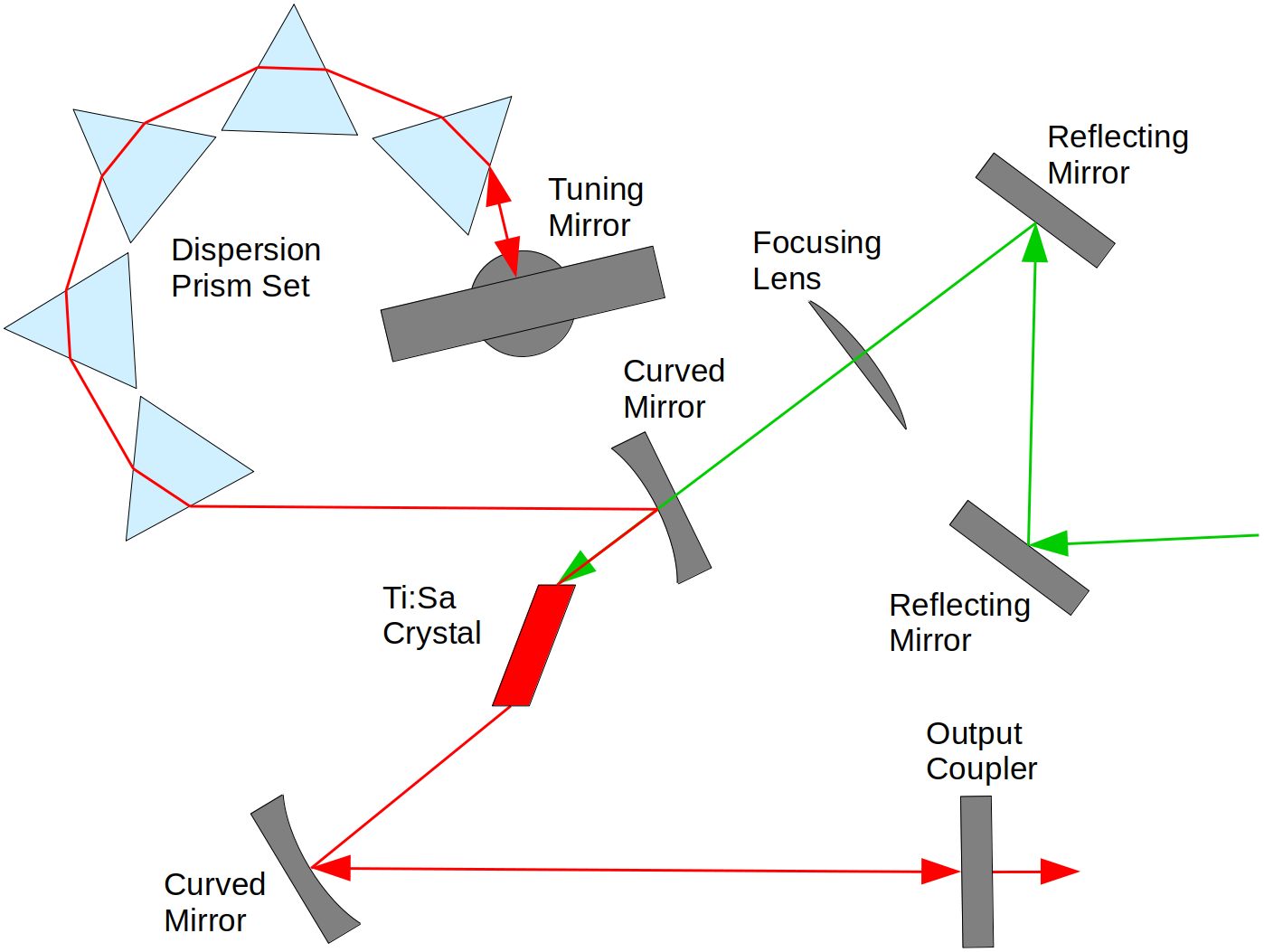
The Nd:YAG pump laser (Nanio 532 from InnoLas Photonics) has a nominal power of 18 W at 10 kHz repetition rate and a quality factor of M2 1.3. The beam is forwarded by two coated dielectric high reflection (HR) mirrors and focused by a plano-convex lens with a focal length of 75 mm before entering the cavity. The Ti:Sa crystal has an absorption coefficient of 1.60 and is situated inside the cavity between two curved mirrors with broadband dielectric coatings with HR 97.7 % for 650 nm to 1040 nm and anti-reflection (AR) 0.2 % for 532 nm. The crystal is placed off-center cavity towards the first curved mirror so that the pump focus is situated right behind the crystal. The broadband output coupler has a reflectivity of 80 % for a wavelength range from 650 nm to 1100 nm and is situated behind the second curved mirror. After the first curved mirror five (four) prisms followed by a high reflection mirror are placed. While the beam passes the prisms dispersion occurs leading to a separation of different wavelengths. At the end of the prisms a rotatable high reflection mirror is placed to select a wavelength and reflect it back into the cavity. The optical elements are all made from fused silica and have a surface flatness of /10 at 633 nm standard.
III Mode matching
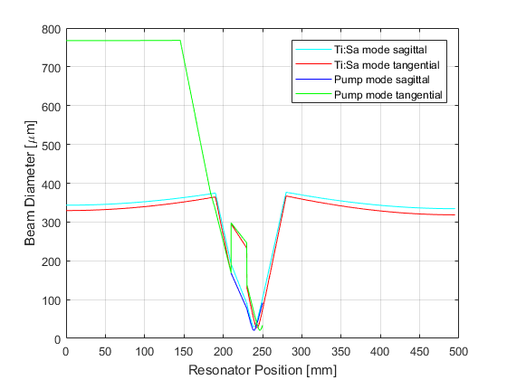
Mode matching means to overlap the modes from the pump laser and the operating laser. This is essential for the operation of the laser and important for maximizing the output power. Therefore the beam path renk2012basics and the corresponding beam diameter hodgson2005beampropagation have to be calculated. The cavity parameters are based on Rothe2012 and are slightly modified to suit the new requirements. All calculations can be seen in Bianca2019 . During the experiment it can be seen that the Ti:Sa crystal is working as a thermal lens probably due to significant radial temperature gradients created by the pump laser which has a M2 1.3 and a pulse duration of 40 ns. The mode matching shown in figure 2 does not account for the effect of thermal lensing. Hence the mode matching needs to be optimized by increasing the distance between the lens and the first curved mirror. That is done in two steps first to 55 mm and second to 70 mm leading to an improved wavelength tuning range of the system.
IV Arrangement of the prisms
To minimize losses through reflectivity it is essential to find an optimal arrangement for the prism setup. For a transition from one material to another the angle of incidence for which light will be perfectly transmitted without reflection losses is the Brewster’s angle Demtroeder2017Experimentalphysik2 . However the Brewster’s angle is not favored when passing through a symmetric prism since the angle exiting the prism will be different. Therefore to minimize the reflectivity losses a path parallel to the prisms base is preferred Meschede2008 . This ideal angle of incidence depends on the aperture angle of the prism and is given by
| (1) |
where is the refractive index of the prism Meschede2008 . Through the refractive index the angle of incidence indirectly depends on the wavelength. Therefore the angles of incidence and emergence after every prism will differ for all wavelengths for which the setup was not optimized for and need to be calculated iteratively shown in Bianca2019 . The level of reflectivity of light hitting a surface can then be determined by Fresnel’s equations depending on its polarization nolting2011elektrodynamik . For p-polarized light the reflectivity losses are given by
| (2) |
where is the refractive index of air and is the refractive index of the prism nolting2011elektrodynamik . Additionally the refractive index of the prisms is of great interest for the optimal arrangement. The first experiments are done with five prisms made from fused silica. Their refractive index is 1.45 at a wavelengths of 800 nm Malitson:65 for which the setup is optimized. A second round of experiments is done with four prisms made out of SF10 (dense flint) and a refractive index of 1.71 at a wavelength of 800 nm SF10 . The optimal angle of incidence is calculated with equation (1). Therefore the angle between the prisms is 41.74∘ for the five prism setup and 58.79∘ for the four prism setup.
V Reflectivity
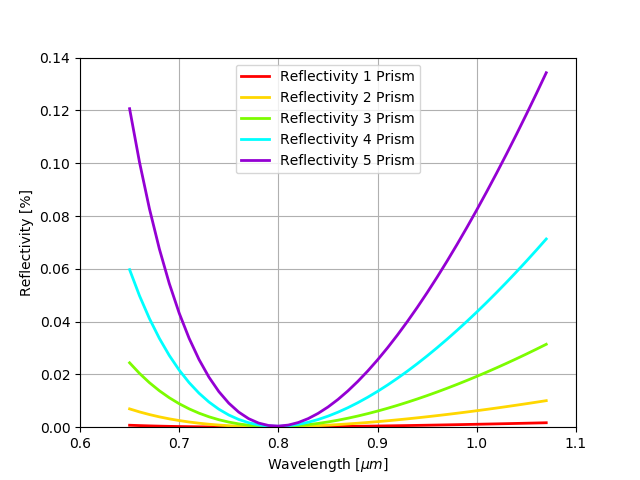
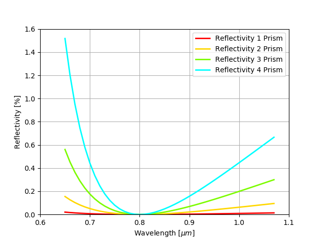
The losses through reflectivity are calculated with equation (2) and depend on the changing angle of incidence. This angle is different for every wavelength and differs more and more with every prism passed. The reflectivity losses shown in figure 3 cover the theoretical tuning range of a Ti:Sa laser from 650 nm to 1070 nm. The current setup is tunable from around 700 nm to 920 nm and therefore has much lower reflectivity losses. The five prism setup is shown in figure 3(a) and the four prism setup in figure 3(b). In the case of the five prism setup the highest reflectivity losses are 0.04 % for a wavelength of 920 nm. For the four prism setup the highest reflectivity losses are 0.3 % for a wavelength of 730 nm.
VI Tuning range
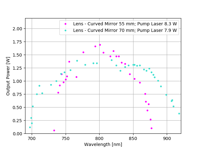
Since the pump laser is operating unstable in the region between 7.5 W and 10 W the pumping power was adjusted for every experiment. Therefore it is increased as long as the output power at a wavelength of 800 nm increases too. Additionally an etalon is placed between the second curved mirror and the output coupler. With a subsequently optimized mode matching the tuning range is increased to around 220 nm reaching from 700 nm to 920 nm which is shown in figure 4(a). Furthermore one can see that the gain of the system at a wavelength of 800 nm is roughly 20 % in the configuration where the lens is placed 55 mm away from the curved mirror. The linewidth in this setup is GHz for a wavelength of 800 nm. The gain for the second configuration with a distance of 70 mm between the two optical elements is around 18 % with a linewidth of GHz; both parameters are measured at a wavelength of 800 nm.
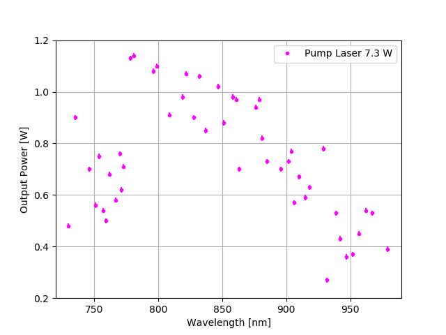
For the setup with four prisms the tuning range is a bit higher with approximately 240 nm reaching from 730 nm to 970 nm. However the operation is not as smooth and a second etalon has to be placed inside the cavity. The tuning range is shown in figure 4(b). The gain in this setup is approximately 15 % and the linewidth is GHz; both parameters are measured at a wavelength of 800 nm.
VII Conclusion
The investigated laser system seems to be promising but the implementation needs improvement. A better way of fixing the prisms on their mount needs to be found. In the presented experiments the prisms only sat on a piece of paper which made them assailable to even very small vibrations. The entire system could not run in a stable mode and therefore lost lasing very easily. The pumping source needs to be switched or the pump laser should be run at higher power and reduced afterwards with suitable optical elements to overcome the region where it operates unstable.
The tuning range of up to 240 nm is already very broad and could probably benefit from a more stable running system as well. To reduce the linewidth more dispersion or deviation of the beam through the prisms would be preferred. To not increase the reflection losses one should keep on working with the prisms with a lower refractive index and increase the distances between them. This would automatically mean to rearrange the optical elements in the cavity. This could additionally bring some benefits: one should focus on using the parameters given in Rothe2012 for best stability, swap the high reflector and output coupler back into their earlier positions so that the pumping beam and the laser beam emerge from opposite sides and one could fit a more suitable rotatable high reflector into the cavity. Due to space problems a mirror mount for the high reflector had to be used where the mirror sits in an arm shaped mount so that the entire arm moved back and forth and not only the angle of the mirror changed.
The reached gain of up to 20 % is not bad but can certainly be improved. Due to the fact that the prisms were not fixed their positions were always slightly off the calculated ones probably leading to higher reflection losses. Furthermore when the deviation of the beam is increased by more space between the prisms one etalon or even both could be removed from the cavity which definitely would increase the gain by at least 2 %.
The overall result is that the adapted laser system looks very promising but more time is required to do more measurements.
References
- (1) J. Lassen, P. Bricault, M. Dombsky, J.P. Lavoie, Ch. Geppert, K. Wendt, Resonant Ionization Laser Ion Source Project at TRIUMF, Hyperfine Inetractions, 162, 69–75 (2005)
- (2) R. Li, J. Lassen, S. Rothe, A. Teigelhöfer and M. Mostamand, Continuously tunable pulsed Ti:Sa laser self-seeded by an extended grating cavity, Opt. Express, 25, 1123–1130 (2017)
- (3) A. Teigelhöfer, P. Bricault, O. Chachkova, M. Gillner, J. Lassen, J.P. Lavoie, R. Li, J. Meißner, W. Neu, K.D.A. Wendt, Grating tuned Ti:Sa laser for ion-source spectroscopy of Rydberg and autoionizing states, Hyperfine Interactions, 196, 161–168 (2010)
- (4) M. Strotkamp, A. Munk, B. Jungbluth, K. Dahlhoff, P. Jansen, S. Broch, S. Gomm, M. Bachner, H. Fuchs, F. Holland, A. Hofzumahaus, Design of a rugged 308 nm tunable UV laser for airbone LIF measurements on top of Zeppelin NT, International Society for Optics and Photonics, 8599, 85990L (2013)
- (5) B. Jungbluth, Gewinngeschaltete Ti:Saphir-Laser mit ultrabreitem Abstimmbereich, Ph.D. thesis, Rheinisch-Westfälische Technische Hochschule Aachen (2010)
- (6) K. F. Renk, Basics of laser physics. Springer (2012)
- (7) N. Hodgson, H. Weber, Laser, Resonators and Beam Propagation. Springer (2005)
- (8) S. Rothe, An all-solid state laser system for the laser ion source RILIS and in-source laser spectroscopy of astatine at ISOLDE/CERN, Ph.D. thesis, Johannes Gutenberg University Mainz (2012)
- (9) B. B. Reich, Development of a widely tunable titanium-sapphire laser system for the ARIEL laser ion source, B.Sc. thesis, University of Heidelberg (2019)
- (10) W. Demtröder, Experimentalphysik 2: Elektrizität und Optik. Springer (2017)
- (11) D. Meschede, Optik, Licht und Laser. Vieweg+Teubner, Wiesbaden (2008)
- (12) W. Nolting, Grundkurs Theoretische Physik 3, Elektrodynamik. Springer (2011)
- (13) I. H. Malitson, Interspecimen Comparison of the Refractive Index of Fused Silica, J. Opt. Soc. Am., 55, 1205–1209 (1965)
- (14) SCHOTT, Refractive index database, SCHOTT Zemax catalog (2017)