Acoustic ferromagnetic resonance and spin pumping induced by surface acoustic waves
Abstract
Voltage induced magnetization dynamics of magnetic thin films is a valuable tool to study anisotropic fields, exchange couplings, magnetization damping and spin pumping mechanism. A particularly well established technique is the ferromagnetic resonance (FMR) generated by the coupling of microwave photons and magnetization eigenmodes in the GHz range. Here we review the basic concepts of the so-called acoustic ferromagnetic resonance technique (a-FMR) induced by the coupling of surface acoustic waves (SAW) and magnetization of thin films. Interestingly, additional to the benefits of the microwave excited FMR technique, the coupling between SAW and magnetization also offers fertile ground to study magnon-phonon and spin rotation couplings. We describe the in-plane magnetic field angle dependence of the a-FMR by measuring the absorption / transmission of SAW and the attenuation of SAW in the presence of rotational motion of the lattice, and show the consequent generation of spin current by acoustic spin pumping.
I introduction
Arguably, one of the most enlightening works by the late physicist Charles Kittel111Charles Kittel passed away the last 15th of May 2019 at the age of 102 is the theoretical description of the ferromagnetic resonance absorption, published first in 1947 Kittel47 and extended to shape anistropies in 1948 Kittel48 . At these early works, Kittel described the magnetization dynamics exerted in a ferromagnetic specimen subjected to a strong dc field and a weak perpendicular microwave field , such that the magnetization dynamics can be well described by ; where is the gyromagnetic ratio, the magnetization and is the external field with components . If the dc field is in-plane and strong enough to fully align the magnetization , then the magnetization precess as a single magnetic domain, a phenomenon we know nowadays as ferromagnetic resonance (FMR). The corresponding frequency at the resonance condition is described by the so-called Kittel formula .
Nowadays, the FMR is a versatile tool that allows studying magnetization dynamics in thin films Bilzera , spin waves Boone , magnetization switching Thirion and spin pumping Rojas . Remarkably, 10 years after his description of FMR, it was the same Charles Kittel who first formulated the coupling of spin waves (magnons) and lattice vibrations (phonons) at resonance conditions, giving origin to the acoustic excited FMR Kittel58 . One initial conclusion was that microwave phonons were necessary for reaching the resonance condition. Conveniently, microwave phonons can be generated by interdigital transducers fabricated on top of piezoelectric substrates. Additional to the previous description of applications of standard FMR (microwave field excited), Kittel suggested that magnetic bulk crystals may show nonreciprocal acoustic properties, and induce strong phonon attenuation.
Here, we first overview the main characteristics of acoustic ferromagnetic resonance (a-FMR) excited by GHz frequency surface acoustic waves (SAW). Then, we review the description of the magnetization coupling with elastic rotation and its dependence when varying in-plane magnetic field Mingran ; Dreher . Furthermore, we recalled an example of the generation of spin current by a-FMR, the so-called acoustic spin pumping. We show that the order of magnitude of the spin current density is of the same order of the more standard spin pumping mechanism excited by microwave photons. Additional to the most recent works of a-FMR Mingran ; Dreher , we describe the less explored coupling of magnetization with lattice rotation, first published more than 40 years ago by one of the authors of the present review Maekawa . Finally, beyond the a-FMR study we conclude with an outlook for the coupling of SAW with magnetic and nonmagnetic materials for spintronic research and applications.
II Acoustic ferromagnetic resonance
II.1 Surface acoustic waves
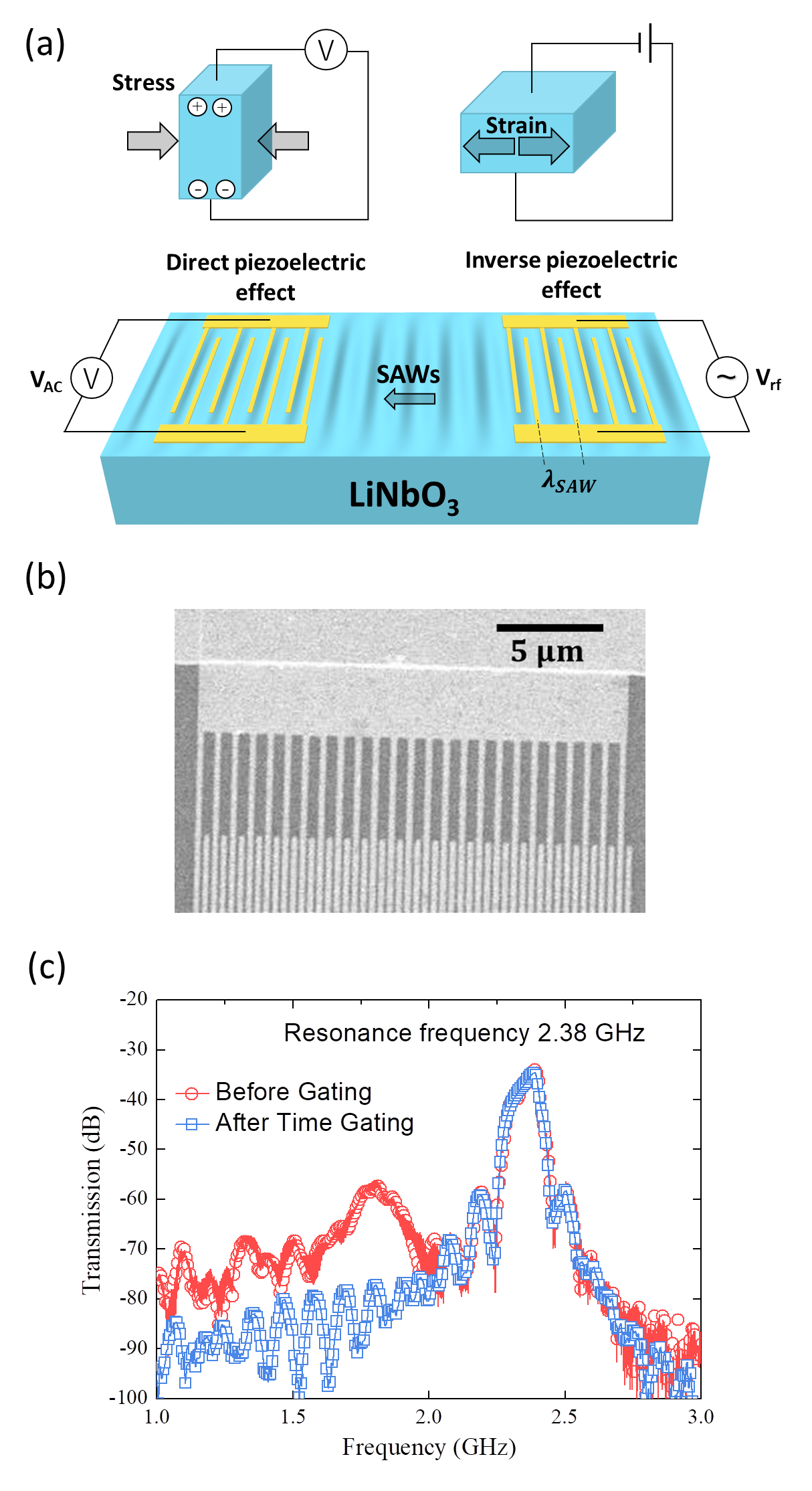
As its name suggests, surface acoustic waves (SAW) are elastic waves that travel parallel to the surface of an elastic material, with a decay perpendicular to the surface into the bulk with an approximated decay length equal to the acoustic wavelength . Figure 1(a) shows the schematics of a two port interdigital transducer (IDT) device on a piezoelectric substrate (LiNbO3, Lithium Niobate) for generation of SAW, the wavelength of acoustic waves, , depends on the periodicity of IDTs as also shown in the schematics. The generation of SAW is done by the inverse piezoelectric effect, where elastic deformation is produced by injection of rf-voltage. The reading of SAW is done by the direct piezoelectric effect, converting elastic deformation back to voltage signal. The SAW frequency is defined by , where is the sound velocity of the piezoelectric material. Figure 1(b) shows a scanning electron microscope (SEM) image of IDTs with 400 nm width and m. The IDTs are patterned by electron beam lithography and made of Ti(5nm)/Au(30nm) by the lift-off method. Since the sound velocity m/s in LiNbO3, we expect the generation of SAW with an approximate frequency GHz. Figure 1(c) shows the characterization of the scattering parameter for transmission S12 by a vector network analyzer (VNA), giving a SAW resonance frequency GHz. The voltage generation of SAW also induces generation of spurious electromagnetic waves (EMW); since the SAW and EMW velocities are different, it is possible to filter out the EMW by a technique called time-gating that employs Fourier transform operations. IDTs act not only as the generator and receiver for acoustic phonons, but also as an antenna, receiving the microwave signals through the air. And acoustic phonon is propagating in a speed of , which is in thousand meters per second level, while the velocity of EMW is approximately 3108 m/s. Hence, SAW signal arrive to the second IDT port after the EMW. As an additional function of our VNA, we are able to analyze the signal in time-domain. In order to rule out the noise brought by the EMW, we set a gate in time-domain, to take the signal which arrives in the interval expected according the the SAW velocity and the lenght of our device. And by using Fourier transform, we obtain frequency-domain signal. The comparision of the signal with and without time gating is presented in figure 1(c).
II.2 Magnetization coupling with elastic strain
When SAWs propagate on a ferromagnetic layer it produces a time variant strain tensor field in the lattice, which couples to the local magnetic environment via the magnetoelastic effect; as a consequence a time varying magnetic field is exerted. Here, we describe how this time varying magnon-phonon coupling induces a-FMR.
Let us start by describing first the dynamics exerted on the normalized magnetization vector when an effective driving magnetic field is present. Such dynamics are described by the Landau-Lifshitz-Gilbert (LLG) equation
| (1) |
where is the Gilbert damping constant and the gyromagnetic ratio is taken as negative. In standard FMR the is given by the magnetic field generated by microwave photons, commonly achieved by coplanar waveguides. In a SAW excited a-FMR, the magnetoelastic coupling links the time dependent lattice strain tensor to the magnetic environment. To calculate as a function of the strain tensor components and magnetization components where ; we phenomenologically postulate the thermodynamic relation of Gibbs , which should be valid for linear response around equilibrium: Follwing Dreher et al. Dreher , we have introduced where is the free energy density normalized by in a ferromagnet, which may for instance be taken to be
| (2) |
Here is the shape anisotropy and is the in-plane uniaxial anisotropy along the unit vector . Although one could further include other terms such as dipole-dipole and exchange interactions, the detailed form of is largely irrelevant in the following discussions and we omit them here. is the magnetoelasitc contribution to the (-normalized) free energy density, which for a cubic crystal reads
| (3) |
where are the magnetoelastic coupling constants. We define a new coordinate system () so that the magnetization components are accordingly (); where the equilibrium direction of the magnetization lies in (), while and are the small dynamical components perpendicular to each other and perpendicular to (see schematic in fig. 2(a)). Now we can expand the effective field under the influence of magnetoelastic coupling to first order in
| (4) |
Here and , are constants whose details are not needed. The transverse components of the strain induced field are given shortly while the longitudinal component is irrelevant in our present setup. Since the components of the driving field that induce a-FMR are those transverse to the equilibrium of magnetization (), we rewrite the LLG equation in its matrix form as
| (5) |
Solving for the transverse components (, ) to the magnetization in equilibrium , we have
| (6) |
where is the Polder susceptibility tensor which describes the dependence on the material parameters and static magnetic field following from the free energy density of Eq. (2)
| (7) |
and are the transverse components of the driving field induced by elastic strain, such that
| (8) | ||||
| (9) |
We observe that different from conventional FMR, the a-FMR has a strong dependence in the angles (out of plane angle) and (in plane angle) between the magnetization and the strain components . Rayleigh waves in SAW contain the strain components , , where the dominant component is the longitudinal strain (). For a pure longitudinal strain when the is in-plane configuration , the maximum value of the driving field is at where the magnetoelastic torque is larger, and vanishes at and , as schematically shown in fig. 2(b). This angle dependence gives origin to the now characteristic four-fold butterfly shape of the a-FMR excited by SAW Mingran ; Dreher ; Wieler . While the SAW power absorption is in general proportional to the imaginary part of Dreher , its angular dependence in the in-plane configuration is well-captured by the approximate formula Mingran
| (10) |
where are the amplitudes of respectively and corresponds to the SAW propagation along directions.
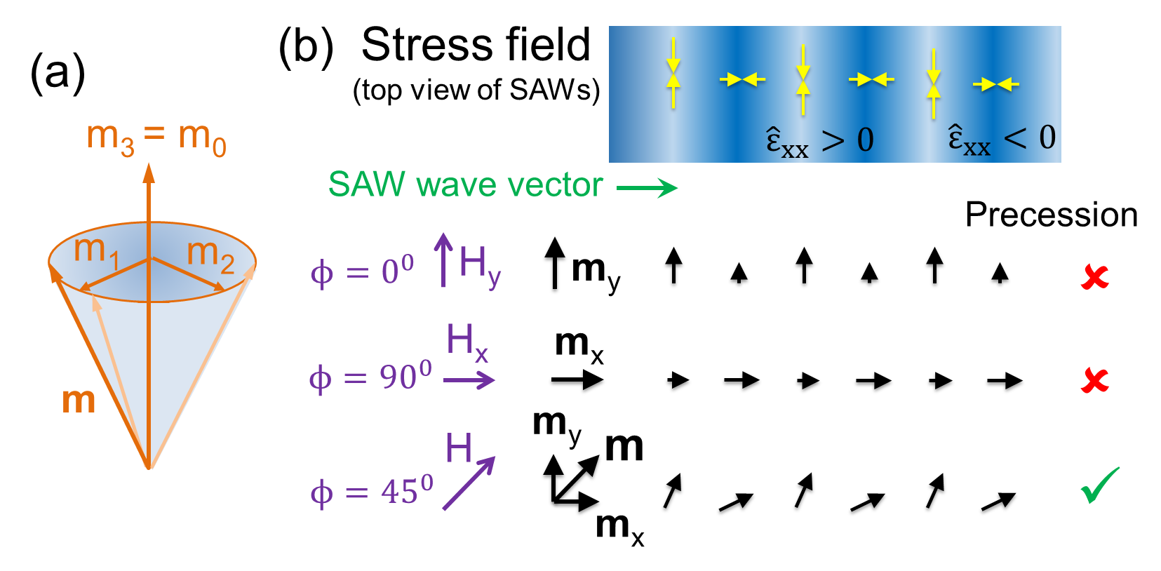
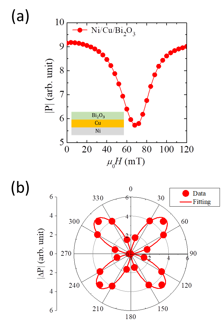
Figure 3(a) shows the spectrum at resonance condition for FMR driving of a Ni layer of 10nm within a Ni/Cu/Bi2O3 heterostructure (inset), with an external magnetic field angle . The full in-plane magnetic field angle dependence of the SAW power absorption shows the four-fold butterfly shape of a-FMR in figure 3(b) which is well-fitted by Eq. (10).
II.3 Possible role of magnetization coupling with lattice rotation
The four-fold butterfly shape is expected to be symmetric for pure longitudinal strain , however, an asymmetric distribution may arise due to the contribution of the shear strain . Such asymmetric SAW absorption of a-FMR has recently received increasing attention Mingran ; Onose . The origin of the asymmetric SAW absorption on these works was explained as interference of the longitudinal () and shear () strain components. Under this scenario one may expect that the shear strain component should be dominant or at least comparable to the longitudinal strain Onose . However, in the thin film limit, , where is the wavevector and the film thickness, the shear strain is strongly suppressed and longitudinal strain is dominant.
Even though the shear strain is strongly suppressed in the thin film limit, Maekawa and Tachiki theoretically demonstrated that a rotational deformation of the lattice survives and can couple to the magnetic anisotropy (out of plane, i.e. along -direction) Maekawa , where the displacement vector components and are given by
| (11) | ||||
| (12) |
where A is the amplitude of the SAW, , , with and being the transverse and longitudinal sound velocities. One can compute as
| (13) |
is given by the ratio of the velocities and . Following Maekawa , different from the standard magnetoelastic coupling, here the rotational deformation couples to the uniaxial crystal anisotropy (out of plane, ) asociated with a spin in the -th site, such that
| (14) |
If we insert Eq. (13) in Eq. (14) we obtain the Hamiltonian describing the interaction between SAW and spins via the rotational deformation
| (15) |
where is the -component of the position vector for the -th site. The interaction described by Eq. (15) implies that SAW may excite surface magnons via rotational motion, and induce SAW attenuation even in the absence of shear strain.
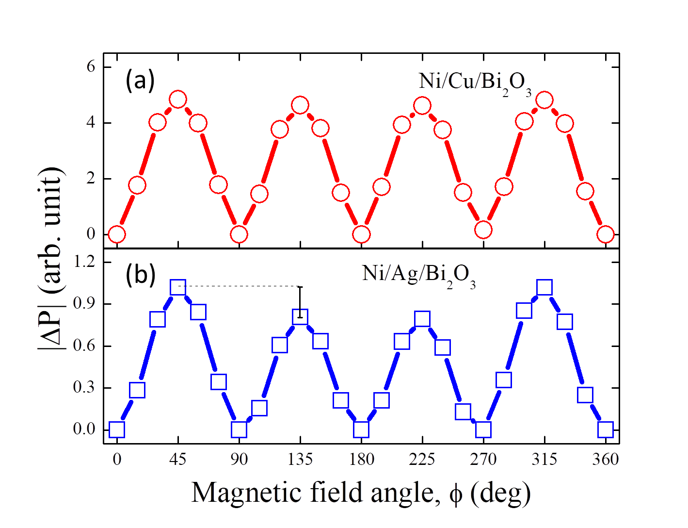
Figure 4 shows a comparison of the in-plane magnetic field dependence of SAW attenuation for Ni/Cu/Bi2O3 and Ni/Ag/Bi2O3. Although, nominally both heterostructures contain similar Ni and Bi2O3, and Cu and Ag posses similar acoustic attenuation, it is possible to observe a significant difference in the asymmetric behavior of SAW absorption between the two heterostructures. In a previous report, we attributed such difference in asymmetric SAW absorption to interference of longitudinal and shear waves Mingran , as was also suggested for other systems Onose . However, the authors have recently become aware of a report suggesting enhancement of magnetic anisotropy energy in the Ag/Ni interface Tsay . Such enhancement of magnetic anisotropy most likely is the result of spin reorientation due to intefacial spin orbit coupling; however, further studies are necessary to clarify it. Together with recent independent experiments paper , this asymmetric absorption in figure 4, may be due to the lattice rotation coupling with magnetization as described by Eq. (15).
III Acoustic spin pumping
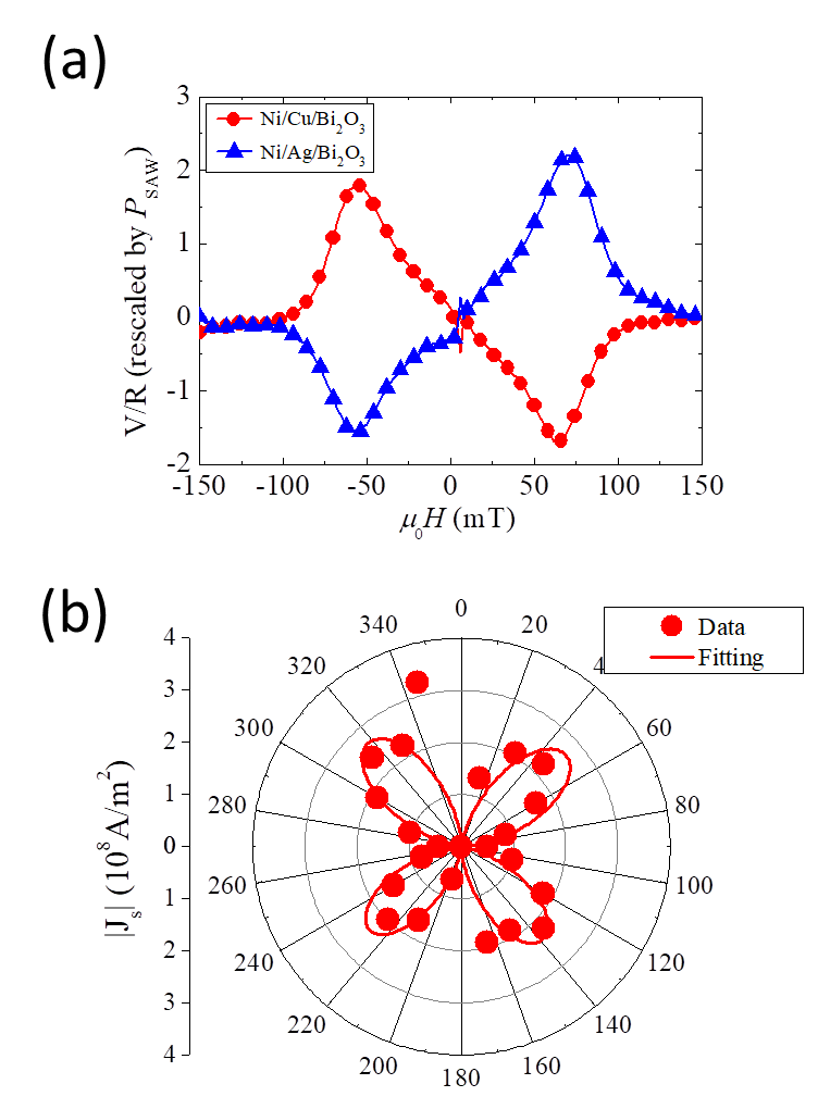
As described by Tserkovnyak et al Yaro ; Yaro2 , magnetization dynamics following the LLG equation can pump spin current from a ferromagnetic layer into a nonmagnetic metal. Such spin pumping is the result of loss of torque acting in the magnetization vector, and can be directly related to enhancements in the Gilbert damping . The conservation of angular momentum indicates that the damping of magnetization precession can pump angular momentum or spin current into an adjacent layer. The spin current generated by acoustic ferromagnetic resonance can be converted to charge current by either inverse spin Hall effect (ISHE) Saitoh ; Wieler2 or inverse Edelstein effect (IEE) Mingran . Figure 5(a) shows the IEE signal rectified at the Cu/Bi2O3 (red circles) and Ag/Bi2O3 (blue triangles) interfaces. The opposite signs of rectified signal reflect the opposite Rashba spin splitting at these two interfaces Jorge . We can use the IEE signal to estimate the generated spin current density with the following formula taken from Mingran
| (16) |
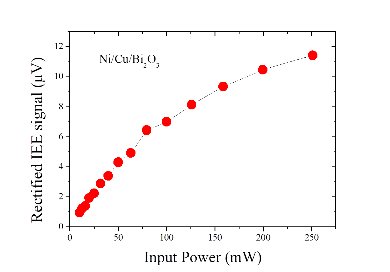
where is the voltage signal detected while the magnetic field is applied at angle , is the inverse Edelstein length, is the sample width and the electric sample resistance. Figure 5(b) shows the angle dependence of the spin current density for Ni/Cu/Bi2O3, with the following parameters: nm, m, . The angle dependence of spin current density shows similar behavior of that of the power absorption of SAW presented in figure 3(b). The spin current density is in the order of 108 A/m2, same order of magnitude to spin current density generated by standard microwave photon FMR Rojas ; Hoff . For completeness, we show in figure 6 the power dependence of IEE signal rectified at the Cu/Bi2O3 interface. As the input power increases the IEE voltage increases monotonically. At low input powers the signal can be approximated to a linear increase, however, at high input power the signal increases nonlinearly.
IV Conclusion and outlook
We provided an overview of the basic characteristics of SAW and description of the magnon-phonon coupling that triggers acoustic ferromagnetic resonance. We extended our discussion in a relatively yet unexplored coupling mechanism of lattice rotation and magnetic anisotropies Maekawa . Such coupling mechanism offers a novel direction for promoting SAW asymmetric attenuation. Enhancement and modulation of asymmetric electrical charge conductivity in electronic circuits allowed the development of the electronic diode technology. The coupling mechanism between magnetic anisotropy and lattice rotation paves the way to explore significant enhancements of asymmetric SAW attenuation in the GHz frequency range, with potential for the development of the magneto-acoustic analog to an electronic diode paper . We described and showed the spin current density generated by a-FMR, the so-called acoustic spin pumping. The order of magnitude of the spin current density Js is comparable to that produced by standard FMR technique. Here, acoustic wave reflectors reflectors may represent an opportunity for further enhancement of the generated spin current densities in acoustic spin pumping. Beyond the specific topic presented here, SAW can also couple to nonmagnetic layers via the so-called spin rotation coupling and generate spin currents in the absence of magnetic materials or external magnetic fields Matsuo . Initial experimental evidence of spin rotation coupling has been recently reported via spin transfer torque mechanism in Cu/NiFe bilayer Nozaki . However, it would be interesting to demonstrate the generation of SAW induced spin current in an all-nonmagnetic structure. Coupling involving SAW has multiple applications that range from wireless technology, sensing, biology to control of elemental charges in condensed matter and coupling to quantum states of matter Roadmap , which offers opportunities for interdisciplinary research and device developments.
This work was supported by Grants-in-Aid for Scientific Research on Innovative Areas (No. 26103001, No. 26103002) and JSPS KAKENHI (No. 19H05629). MX was supported by JSPS KAKENHI (No. JP19J21720). KY would like to acknowledge support of JSPS KAKENHI (JP 19K21040). SM was financially supported by ERATO, JST, and KAKENHI (No 17H02927 and No. 26103006) from MEXT, Japan.
References
- (1) C. Kittel, Interpretation of Anomalous Larmor Frequencies in Ferromagnetic Resonance Experiment, Phys. Rev. 71, 270 (1947)
- (2) C. Kittel, On the theory of ferromagnetic resonance absorption, Phys. Rev. 73, 155 (1948)
- (3) C. Bilzera, T. Devolder, J.-V. Kim, G. Counil, and C. Chappert, Study of the dynamic magnetic properties of soft CoFeB films, Journal of Applied Physics 100, 053903 (2006)
- (4) C. T. Boone, J. A. Katine, J. R. Childress, V. Tiberkevich, A. Slavin, J. Zhu, X. Cheng, and I. N. Krivorotov, Resonant Nonlinear Damping of Quantized Spin Waves in Ferromagnetic Nanowires: A Spin Torque Ferromagnetic Resonance Study, Phys. Rev. Lett. 103, 167601 (2009)
- (5) C. Thirion, W. Wernsdorfer and D. Mailly, Switching of magnetization by nonlinear resonance studied in single nanoparticles, Nature Material 2, 524–527 (2003)
- (6) J.-C. Rojas-Sanchez, N. Reyren, P. Laczkowski, W. Savero, J.-P. Attane, C. Deranlot, M. Jamet, J.-M. George, L. Vila, and H. Jaffres, Spin Pumping and Inverse Spin Hall Effect in Platinum: The Essential Role of Spin-Memory Loss at Metallic Interfaces, Phys. Rev. Lett. 112, 106602 (2014)
- (7) C. Kittel, Interaction of Spin Waves and Ultrasonic Waves in Ferromagnetic Crystals, Phys. Rev. 110, 836 (1958)
- (8) M. Xu, J. Puebla, F. Auvray, B. Rana, K. Kondou, Y. Otani, Inverse Edelstein effect induced by magnon-phonon coupling, Physical Review B 97 (18), 180301 (2018)
- (9) L. Dreher, M. Weiler, M. Pernpeintner, H. Huebl, R. Gross, M. S. Brandt, and S.T. B. Goennenwein, Surface acoustic wave driven ferromagnetic resonance in nickel thin films: Theory and experiment, Phys.Rev.B86, 134415 (2012).
- (10) S. Maekawa and M. Tachiki, Surface acoustic attenuation due to surface spin wave in ferro‐ and antiferromagnets, AIP Conf. Proc. 29, 542 (1976)
- (11) M.Weiler, L. Dreher, C. Heeg, H. Huebl, R. Gross, M. S. Brandt, and S. T. B. Goennenwein, Elastically Driven Ferromagnetic Resonance in Nickel Thin Films, Phys. Rev. Lett. 106, 117601 (2011)
- (12) R. Sasaki, Y. Nii, Y. Iguchi, and Y. Onose, Nonreciprocal propagation of surface acoustic wave in Ni/LiNbO3, Phys. Rev. B 95, 020407 (2017)
- (13) M. Xu, K. Yamamoto, J. Puebla, K. Baumgaertl, B. Rana, K. Miura, H. Takahashi, D. Grundler, S. Maekawa and Y. Otani, Tunable acoustic wave rectification in anisotropic magnets, arXiv:2001.05135 [cond-mat.mes-hall] (2020)
- (14) Y.-T. Chow, B.-H. Jiang, C.-H.-T. Chang and J.-S. Tsay, Enhancing the magnetic anisotropy energy by tuning the contact areas of Ag and Ni at the Ag/Ni interface, Phys. Chem. Chem. Phys., 20, 1504 (2018)
- (15) Y. Tserkovnyak, A. Brataas, and G.E.W. Bauer, Enhanced Gilbert Damping in Thin Ferromagnetic Films, Phys. Rev. Lett. 88, 117601 (2002)
- (16) Y. Tserkovnyak, A. Brataas, and G.E.W. Bauer, Spin pumping and magnetization dynamics in metallic multilayers, Phys. Rev. B 66, 224403 (2002)
- (17) K. Uchida, T. An, Y. Kajiwara, M. Toda, and E. Saitoh, Surface-acoustic-wave-driven spin pumping in Y3Fe5O12/Pt hybrid structure, Appl. Phys. Lett. 99, 212501 (2011)
- (18) M. Weiler, H. Huebl, F. S. Goerg, F. D. Czeschka, R. Gross, and S. T. B. Goennenwein, Spin Pumping with Coherent Elastic Waves, Phys. Rev. Lett. 108, 176601 (2012)
- (19) J. Puebla, F. Auvray, M. Xu, B. Rana, A. Albouy, H. Tsai, K. Kondou, G. Tatara, and Y. Otani, Direct optical observation of spin accumulation at nonmagnetic metal/oxide interface, Appl. Phys. Lett. 111, 092402 (2017)
- (20) W. Zhang, M. B. Jungfleisch, W. Jiang, J. E. Pearson, and A. Hoffmann, Spin pumping and inverse Rashba-Edelstein effect in NiFe/Ag/Bi and NiFe/Ag/Sb, J. Appl. Phys. 117, 17C727 (2015)
- (21) T. R. Joseph, K. M. Lakin, and D. Penunuri, Surface acoustic wave planar resonator using grating reflectors, Appl. Phys. Lett. 26, 29 (1975)
- (22) M. Matsuo, J. Ieda, K. Harii, E. Saitoh, and S. Maekawa, Mechanical generation of spin current by spin-rotation coupling, Phys. Rev. B 87 180402 (2013)
- (23) D. Kobayashi, T. Yoshikawa, M. Matsuo, R. Iguchi, S. Maekawa, E. Saitoh, and Y. Nozaki, Spin Current Generation Using a Surface Acoustic Wave Generated via Spin-Rotation Coupling, Phys. Rev. Lett. 119, 077202 (2017)
- (24) P. Delsing, et al, The 2019 surface acoustic waves roadmap, J. Phys. D: Appl. Phys. 52 353001 (2019)