] ] ]
Gravitational waves detection with exceptional points in micro cavities
Abstract
Here we propose a new gravitational waves(GWs) detector in broad frequency band, which is operated at exceptional points(EPs) in micro cavities. The detected signal is an eigenfrequency split of the mechanical modes caused by the spatial strain. Due to the complex square root topology near the EP, the splitting is greatly enhanced for sufficiently small perturbations. Compared to current strategies, it can be achieved at the room temperature and has advantages in micro device scale, wide frequency band and higher sensitivity.
pacs:
Valid PACS appear hereI INTRODUCTION
According to the quantum mechanical perturbation theory, a perturbation with strength of acting on a two fold-degenerate system will cause the energy shift or energy split in proportion to . Thus it is possible to probe variety of parameters in a system by the frequency spectrum and some sensors are based on this principle[1-4]. There is another type of degeneracy in the open system (exchanging energy with the surrounding environment), called exceptional point (EP). The EP is the spectrum singularity in the parameter space, where two or more eigenvalues and their corresponding eigenvectors coalesce simultaneously. One of the main differences between exception points and conventional degeneration is their sensitivity to perturbations[5-7]. Owing to the complex square-root topology near an EP, any perturbation lifts the degeneracy, leading to a frequency splitting that scales as . Therefore, a smaller perturbation means that the improvement in sensitivity is more significant.
As well known from the general theory of relativity, gravitational waves(GWs) can cause a strain in space. Existing detection strategies are based on long-baseline optical interferometry [8]. The principle is to utilize the time-varying phase shifts caused by GWs in the optical path. Since the wavelengths or frequencies of radiated GWs are determined by the scales of the sources, it is necessary to observe the GWs with various frequency bands to understand the hierarchical structure of the universe. At present, laser interferometer detectors have been improved, and it is expected to directly detect GWs in the 0.1 to 1 kHz band through advanced LIGO technology[9]. Observations of low-frequency GWs have been tried through spaceborne experiments[10-12] and astrophysical observations[13].
In this Letter, we study how micro scale optical cavities can be used to detect gravitational wave radiations. We propose a new GW detection mechanism based on the optomechanical coupling change induced by spatial strain at the EP of the system. This scheme does not rely on a shot-noise limited displacement measurement of test mass mirrors, but rather depends on a precision frequency measurement of the nanomechanical resonators. The eigenfrequency splitting induced by GW can be read out in the high-resolution frequency spectrum. The proposed detector differs from known detectors in at least 4 points: (i) the scale of the device is not limited, here we use the micro cavities for example. (ii) can detect gravitational waves over a wider frequency range. (iii) due to the topological properties at the EP, the sensitivity is greatly improved. (iv) operate at room temperature.
II THEORY FRAMEWORK
Let us begin with the Hamiltonian of coupled mechanical resonators,
| (1) |
Here and are the creation (annihilation) operators of the mechanical modes, and are their mechanical frequencies, denotes the coupling strength between them. The tunable coupling of two mechanical resonators can be achieved through the piezoelectric effect or the photothermal effect[14].
According to the Heisenberg equation of motion and the commutation relations , , From Eq.(1), we can get,
| (2) |
| (3) |
Here we phenomenologically introduce the mechanical damping rate . The resulting equation of motion is
| (4) |
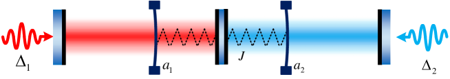
Then we can introduce the gain and lose through the optomechanical method. The schematic of our setup is sketched in Fig.1, where two resonators are optomechanically coupled to two cavities respectively, and simultaneously coupled to each other. Now we can engineer mechanical gain (loss) by driving the cavity with a blue-detuned (red-detuned) laser. According to cavity optomechanics, the optomechanical damping rate is given by [15]
| (5) |
where is the intracavity photon number which can be controlled by the optical drive signal, denote the cavity decay rate, represent the laser detuning from the cavity resonance. The optical frequency shift per displacement is given as . For a simple cavity of length , we have , where is the frequency of single optical mode, is the speed of light in vacuum. And is the vacuum optomechanical coupling strength, expressed as a frequency, here is the zero-point fluctuation amplitude of the mechanical oscillator, and is the effective masses of the resonators. Finally, we express as a function of via
| (6) |
This indicates that smaller cavities yield larger coupling strengths. Since can be both positive and negative, it can either increase or decrease the mechanical damping rate, causes extra damping or antidamping, corresponding mechanical loss or gain. Thus the total mechanical damping rates of the resonators can be expressed as the sum of natural mechanical damping rate and the optomechanical damping rate , hence we have . Then we consider the eigenvalues of the effective Hamiltonian in Eq.(4),
| (7) |
With the simplification, we choose , we use two identical optical cavities and resonators, that means , and . We also use the driving lasers with the identical power to drive both micro cavities simultaneously, this indicates . Thus Eq. (7) simplifies to
| (8) |
Instead of the traditional vibrational mode, we now have new mechanical modes, which can be called as the supermodes. Their mechanical frequencies are Re and spectral linewidths are Im.
III MEASUREMENT MECHANISM
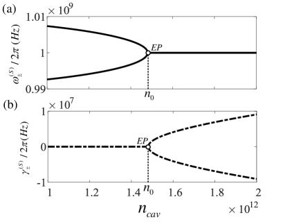
Here we consider the mechanical resonators of Si beams for example, which possess the thickness of , mass , the vibration frequency [16]. Their mechanical coupling strength is usually much less than their resonance frequencies[14], here we use practical device parameter [17]. We use the cavities with length and decay rate . We then set the cavity-pump detunings . From Fig.2 we can see that the parity-time(PT)-broken regime and the PT symmetric regime are separated by the exception point (), where the eigenfrequencies coalesce. As increases, the frequencies of the pair of supermodes approach to each other and coalesce, while the linewidth starts with zero and then branches, indicating that the PT symmetry is broken.
Gravitational wave is the propagation of curvature wave in space-time, which is emitted by accelerated masses. It causes a strain in space perpendicular to the direction in which it propagate. The length change is proportional to the original distance between two places, . We shall see next the splitting of the supermodes can be used as a signal of the gravitational wave due to the length changes of cavities.
An important parameter in a PT symmetrical system is the difference between the eigenfrequencies, namely the eigenfrequency splitting which can be defined as . To evaluate the sensitivity of gravitational wave detection at EP, we need to know the effect of a perturbation on the supermode splitting near the EP. Any perturbation of the cavity length induces a change in vacuum optomechanical coupling strength that affects the eigenvalues as
| (9) |
Here we consider and . The relationship between the change of vacuum optomechanical coupling strength and the length of cavity is given by
| (10) |
The sensitivity can be defined as . The system is at the EP when there is no gravitational wave, thus , so we have . Considering , the result can be simplified as
| (11) |
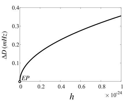
Fig.3 shows as a function of the perturbation near the EP. We can see that the eigenfrequency splitting is proportional to the square root of the perturbation strength . At the EP, both eigenvalues and eigenvectors are coalesce. The perturbation of spatial strain can shift the exceptional point, and thereby the non-Hermitian degeneracy of the eigenfrequencies are released and cause the supermodes to split. Thus our scheme does not rely on a shot-noise limited displacement measurement of mirrors, but rather depends on a precision frequency measurement of the mechanical mode. The minimum measurable frequency difference is usually determined by the mechanical linewidth and noises. Here the linewidths of the mechanical modes are Im. At the EP, , hence , as shown in Fig.2(b). Then we consider the perturbation , , thereby , indicates , the linewidth of the supermodes is still coalesce and equal to 0, so the perturbation will not induce a linewidth increase.
However, various noise processes will cause the increasing of frequency uncertainty. For the nanomechanical resonators, the main noise source is the thermomechanical fluctuations[16]. In such a measurement, the resonator is driven at a constant mean square amplitude , which can be roughly approximated as . According to the fluctuation-dissipation theorem, the frequency fluctuation induced by thermal noise can be calculated by . Here is the mechanical quality factor, is the effective temperature and is the Boltzmann constant. We can see that high mechanical quality and low temperature help reduce the thermal noise. In order to obtain the quantum-noise-limited sensitivity of the strain , we assume that the eigenfrequency split caused by GWs is exactly equal to the frequency stability determined by the thermal noise, this means , then we get the limit under the sample time of .
| (12) |
For the resonator with , the spatial strain resolution of can be achieved at the room temperature (). If the effective temperature of the vibrational modes can be reduced to by using the laser cooling technologies[18,19], the sensitivity can be increased by more than 2 orders of magnitude to reach an unprecedented level of . We can see from Eq.(12) that the sensitivity is independent of cavity length used in our scheme, but using a resonator with higher frequency and smaller mass can improve the detection sensitivity.
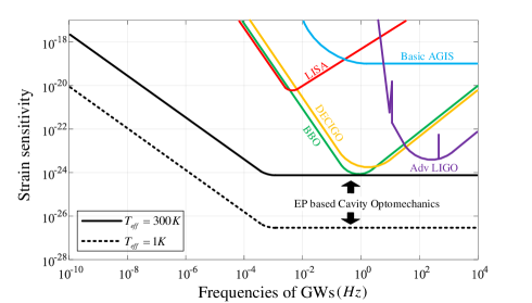
This EP-based optomechanical sensor measures the length changes of the micro cavities. The spectral splitting is proportional to the square root of the amplitude of the GW , regardless of the GW’s frequency. Therefore, the detector’s responses to gravitational waves of arbitrary frequency are consistent. However, considering that the distance changes induced by the ultra-low-frequency gravitational waves are very slow, we estimate the strain sensitivity with a maximum observation time of hour, and compare it with other projects[9-12,20] in Fig.4. It can be clearly seen that the EP-based optomechanical sensor performs better. We hope that the proposed system can advance the search for gravitational wave by an enhanced sensitivity of several orders of magnitude compared with traditional methods in various frequency bands.
IV CONCLUSION
We propose an optomechanical gravitational wave detector based on the exceptional points. The system is a coupled optomechanical system, in which the gain and loss are applied by driving the cavities with a blue detuned and red detuned electromagnetic fields, respectively. When the gain and loss reach a balance, the system will show the degeneracy of exceptional points, and the perturbation of the length of micro cavity will cause an eigenfrequencies split which can be probed with the frequency spectrum, thus the readout noise caused by the beam amplitude can be avoided. Compared with the traditional detectors, the sensitivity is greatly enhanced due to the complex square root topology of EPs in wide frequency band.
Acknowledgements.
This work was supported by the National Natural Science Foundation of China (Nos.11274230 and 11574206), the Basic Research Program of the Committee of Science and Technology of Shanghai (No.14JC1491700).References
- (1) W. Yu, W. C. Jiang, Q. Lin, and T. Lu , Cavity optomechanical spring sensing of single molecules, Nat. Commun. 7, 12311 (2016).
- (2) J. J. Li and K. D. Zhu, All-optical mass sensing with coupled mechanical resonator systems, Phys. Rep. 525, 223 (2013).
- (3) J. Liu and K. D. Zhu, Nanogravity gradiometer based on a sharp optical nonlinearity in a levitated particle optomechanical system, Phys. Rev. D 95, 044014 (2017).
- (4) L. He,Ş. K. Ö zdemir, J. Zhu, W. Kim, and L. Yang, Detecting single viruses and nanoparticles using whispering gallery microlasers, Nat. Nanotechnol. 6, 428 (2011).
- (5) W. Chen,Ş. K. Ö zdemir, G. Zhao, J. Wiersig, and L. Yang, Exceptional points enhance sensing in an optical microcavity, Nature 548, 192–196 (2017).
- (6) J. Wiersig, Sensors operating at exceptional points: General theory, Phys. Rev. A 93, 033809 (2016).
- (7) H. Hodaei, A. U. Hassan, S. Wittek, H. Garcia-Gracia, R. El-Ganainy, D. N. Christodoulides, and M. Khajavikhan, Enhanced sensitivity at higher-order exceptional points, Nature 548, 187–191(2017).
- (8) R. X. Adhikari, Gravitational radiation detection with laser interferometry, Rev. Mod. Phys. 86, 121 (2014).
- (9) K. S. Thorne, Nobel Lecture: LIGO and gravitational waves III, Rev. Mod. Phys. 90, 040503 (2018).
- (10) N. Tamanini and C. Danielski, The gravitational-wave detection of exoplanets orbiting white dwarf binaries using LISA, Nature Astronomy 3, 858 (2019).
- (11) S. Sato, et al., DECIGO : The Japanese space gravitational wave antenna, J. Phys. Conf. Ser. 154, 012040 (2009).
- (12) C. Cutler and D. E. Holz, Ultrahigh precision cosmology from gravitational waves, Phys. Rev. D 80, 104009(2009).
- (13) P. D. Lasky, et al., Gravitational-Wave Cosmology across 29 Decades in Frequency, Phys. Rev. X 6, 011035 (2016).
- (14) X. W. Xu, Y. Liu, C. P. Sun, and Y Li, Mechanical PT symmetry in coupled optomechanical systems, Phys. Rev. A 92, 013852 (2015).
- (15) M. Aspelmeyer, T. J. Kippenberg, and F. Marquardt, Cavity optomechanics, Rev. Mod. Phys. 86, 1391 (2014).
- (16) K. L. Ekincia, Y. T. Yang, and M. L. Roukesb, Ultimate limits to inertial mass sensing based upon nanoelectromechanical systems, J. Appl. Phys. 95, 2682 (2004).
- (17) K. Fang, M. H. Matheny, X. Luan, and O. Painter, Optical transduction and rounting of microwave phonons in cavity optomechanical circuits, Nat. Photonics 10, 489 (2016).
- (18) D. Kleckner and D. Bouwmeester, Sub-kelvin optical cooling of a micromechanical resonator, Nature 444, 75 (2006).
- (19) M.R. Vanner, J. Hofer, G.D. Cole, and M. Aspelmeyer, Cooling-by-measurement and mechanical state tomography via pulsed optomechanics, Nat. Commun. 4, 2295 (2013).
- (20) J. M. Hogan, D. M. S. Johnson, and S. Dickerson, et al., An atomic gravitational wave interferometric sensor in low earth orbit (AGIS-LEO), Gen Relativ Gravit 43, 1953 (2011).