Coordinating Complementary Waveforms for Suppressing Range Sidelobes in a Doppler Band
Abstract
We present a general method for constructing radar transmit pulse trains and receive filters for which the radar point-spread function in delay and Doppler (radar cross-ambiguity function) is essentially free of range sidelobes inside a Doppler interval around the zero-Doppler axis. The transmit and receive pulse trains are constructed by coordinating the transmission of a pair of Golay complementary waveforms across time according to zeros and ones in a binary sequence . In the receive pulse train filter, each waveform is weighted according to an element from another sequence . We show that the spectrum of essentially the product of and sequences controls the size of the range sidelobes of the cross-ambiguity function. We annihilate the range sidelobes at low Doppler by designing the pairs such that their products have high-order spectral nulls around zero Doppler. We specify the subspace, along with a basis, for such sequences, thereby providing a general way of constructing pairs. At the same time, the signal-to-noise ratio (SNR) at the receiver output, for a single point target in white noise, depends only on the choice of . By jointly designing the transmit-receive sequences , we can maximize the output SNR subject to achieving a given order of the spectral null. The proposed constructions can also be extended to sequences consisting of more than two complementary waveforms; this is done explicitly for a library of Golay complementary quads. Finally, we extend the construction of pairs to multiple-input-multiple-output (MIMO) radar, by designing transmit-receive pairs of paraunitary waveform matrices whose matrix-valued cross-ambiguity function is essentially free of range sidelobes inside a Doppler interval around the zero-Doppler axis.
Index Terms:
Complementary sequences, Doppler resilience, Joint transmit-receive design, MIMO radar, MIMO cross-ambiguity, range sidelobe suppression, waveform coordination.I Introduction
Phase coding [3] is a common technique in radar for generating waveforms with impulse-like autocorrelation functions for localizing targets in range. In this technique, a long pulse is phase coded with a unimodular (biphase or polyphase) sequence and the autocorrelation function of the coded waveform is controlled through the autocorrelation function of the unimodular sequence. Examples of sequences that produce good autocorrelation functions are Frank codes [4], Barker sequences [5], and generalized Barker sequences by Golomb and Scholtz [6], polyphase sequences by Heimiller [7], and polyphase codes by Chu [8]. It is however impossible to obtain an impulse autocorrelation with a single unimodular sequence. This has led to the idea of using complementary sets of unimodular sequences [9]–[13] for phase coding.
Golay complementary sequences (Golay pairs), introduced by Marcel Golay [9], have the property that the sum of their autocorrelation functions vanishes at all nonzero lags. Thus, if the waveforms phase coded by Golay complementary sequences (called from here on Golay complementary waveforms) are transmitted separately in time, and their complex ambiguity functions are summed, the result is essentially an impulse in range along the zero-Doppler axis. In some sense, this makes Golay complementary waveforms ideal for separating point targets in range when the targets have the same Doppler frequency. The concept of complementary sequences has been generalized to multiple complementary codes by Tseng and Liu [13], and to multiphase (or polyphase) sequences by Sivaswami [14] and Frank [15]. Properties of complementary sequences, their relationship with other codes, and their applicability in radar have been studied in several articles among which are [9]–[15]. Golay complementary codes have also been used, in conjunctions with space-time coding techniques, to develop waveform matrices with desired correlation and cross-correlation properties [16].
In practice, however, a major obstacle exists to adopting Golay complementary sequences for radar; The perfect auto-correlation property of these sequences is extremely sensitive to Doppler shift. Off the zero-Doppler axis the impulse-like response in range is not maintained and the sum of the ambiguity functions of the waveforms has large range sidelobes. In consequence, a weak target located in range near a strong reflector with a different Doppler frequency may be masked by the range sidelobes of the radar ambiguity function centered at the delay-Doppler position of the stronger reflector. This is particularly problematic for detecting targets in the presence of clutter, because clutter often occupies a Doppler frequency band around zero. All generalizations of Golay complementary sequences, including multiple complementary sequences and polyphase complementary sequences, suffer from the same problem to varying degrees.
In [17] and [18], we showed that, by coordinating the transmission of a pair of Golay complementary waveforms in a pulse train according to the zeros and ones in a binary sequence, called the Prouhet-Thue-Morse (PTM) sequence (see, e.g., [19]), we can produce a pulse train whose ambiguity function is essentially free of range sidelobes in a narrow interval around the zero-Doppler axis, and thereby achieving Doppler resilience. We also extended this idea to constructing a PTM sequence of two by two paraunitary waveform matrices that maintain their paraunitary property at modest Doppler shifts. A generalized PTM sequence was subsequently used in [20] for creating Doppler resilience in multiple-input-multiple-output (MIMO) radar transmissions. Our original PTM construction for single channel radar has recently been tested in simulation for Doppler resilience in automotive radar [21].
In this paper, we extend the idea that we introduced in [17] to the joint design of transmit pulses and receive filters. We develop a systematic approach to sequencing and weighting of Golay complementary waveforms in the transmit pulse train and the receive filter, respectively, to essentially annihilate the range sidelobes of the radar point-spread function inside a Doppler interval around the zero-Doppler axis. We construct the transmit pulse train by coordinating the transmission of a pair of Golay complementary waveforms across consecutive pulse repetition intervals according to a binary sequence (of s and s). The pulse train used in the receive filter is constructed with the same sequencing of Golay waveforms across time, but each waveform in the pulse train is weighted according to an element of a nonnegative sequence . We call such a transmit-receive pair of pulse trains a pair.
We show that the size of the range sidelobes of the cross-ambiguity function of a (P,Q) pair, which constitutes the radar point spread function in range and Doppler, is controlled by the spectrum of essentially the product of and sequences in a very precise way. By selecting sequences for which the spectrum of their product has a higher-order null around zero Doppler, we can annihilate the range sidelobe of the cross ambiguity function inside an interval around the zero-Doppler axis. At the same time, the signal-to-noise ratio (SNR) at the receiver output, defined as the ratio of the peak of the squared cross-ambiguity function to the noise power at the receiver output, depends only on the choice of . By jointly designing the transmit-receive sequences , we can maximize the output SNR subject to achieving a given order of the spectral null.
We discuss two specific designs in detail; namely, the PTM design and the binomial design. In the former, the transmit sequence is the binary PTM sequence of length and the weighting sequence at the receiver is the all-s sequence. In this case, the output SNR in white noise is maximum, as the receiver filter is in fact a matched filter, but the order of the spectral null is only logarithmic in the length of the transmit pulse train. This design was originally introduced in [17]. We present it in this paper for comparison with other designs. In the binomial design, on the other hand, is the alternating binary sequence of length and is the sequence of binomial coefficients in the binomial expansion . In this case, the order of the spectral null is ; the largest that can be achieved with a pulse train of length , but this comes at the expense of SNR.
For general designs, we derive a necessary and sufficient condition for achieving an th-order spectral null with length- pairs. More specifically, we determine the subspace of length sequences that have spectral nulls of order at zero, and identify a basis for this subspace. We also present an alternative characterization of such sequences via a null space condition. We then formulate the problem of designing pairs as one of maximizing the output SNR subject to the subspace constraint for achieving a null of a given order. The signs of the elements of the solution determine the sequence and the moduli of its elements determine the sequence .
We also propose a systematic extension of the above pulse trains to waveform libraries with more than two complementary waveforms. Here, we construct -ary sequences for coordinating the transmission of complementary waveforms and the corresponding sequences for weighting them in the receive filter to suppressing range sidelobes. We present an explicit example of such designs for Golay complementary quads.
Finally, we extend the construction of pairs to multiple-input-multiple-output (MIMO) radar, by designing transmit-receive pairs of paraunitary waveform matrices whose matrix-valued cross-ambiguity function is essentially free of range sidelobes inside a Doppler interval around the zero-Doppler axis.
Remark 1.
We note that this paper concerns the construction of transmit-receive pairs of complementary waveforms that exhibit Doppler resilience, and not the design of unimodular sequences with Doppler resilience, which has been studied by several authors. For example, in [22] and [23] a class of near complementary codes, called subcomplementary codes, that exhibits some tolerance to Doppler shift has been introduced. The term near complementary means that the sum of the autocorrelations of the sequences is not an impulse and has modest sidelobes in delay. Also a large body of work exists concerning the design of single polyphase sequences that have Doppler tolerance. A few examples are Frank codes [4], , , , and sequences [24], sequences [25], and sequences [26],[27]. The design of Doppler tolerant polyphase sequences has also been considered for MIMO radar [28] and for orthogonal netted radar [29].
II Complementary Waveforms and Their Ambiguities
Let denote a baseband pulse shape with duration limited to a chip interval and unit energy:
| (1) |
The ambiguity function of is
| (2) |
where and are delay and Doppler frequency variables, respectively, and ∗ denotes complex conjugation.
A baseband waveform constructed by phase coding translates of with a length unimodular sequence can be be expressed as
| (3) |
The energy of is
| (4) |
The ambiguity of at delay-Doppler coordinates is
| (5) |
where
| (6) |
for .
Definition 1: Golay Complementary Pair [9]. Two length unimodular sequences of complex numbers and form a Golay complementary pair if, for all lags , their summed autocorrelation functions satisfies
| (7) |
where and are the autocorrelations of and at lag , respectively, and is the Kronecker delta function. From here on, we may drop the discrete time index from and and simply use and when appropriate.
Remark 2.
The sequences and are Golay complementary. Golay complementary sequences of length can be constructed recursively from Golay complementary sequences of length for . Let be a matrix, in which every pair of rows is Golay complementary. Partition as
| (8) |
where and are matrices. Then, can be constructed from as [9]
| (9) |
The following example shows the construction of Golay complementary sequences of length four from those of length two:
| (10) |
A pair of baseband waveforms and , phase coded by length- Golay complementary sequences and : that is,
and
individually, have ambiguity functions and , as in (5), with and replacing .
Separating the transmissions of and in time by a pulse repetition interval (PRI) of seconds results in the radar waveform with the ambiguity function
| (11) |
Remark 3.
The ambiguity function of has two range aliases (cross terms) offset from the zero-delay axis by . In this paper, we ignore the range aliasing effects and refer to as the ambiguity function of . Range aliasing effects can be accounted for using standard techniques (for instance, see [3]) and will not be further discussed.
As the duration of the waveforms and is typically much shorter than the PRI duration , the Doppler shift over , i.e., is negligible compared to the Doppler shift over a PRI, i.e., , for practically feasible targets . A fortiori this applies to the Doppler shift over an individual chip (a single translate of ). As a result, we can approximate as
| (12) |
Noting that , , and defining as the autocorrelation function of , that is, , we have
| (13) |
Along the zero-Doppler axis (), the ambiguity function reduces to
| (14) |
by complementarity of the Golay pair and . We observe that the ambiguity function is “free” of range sidelobes along the zero-Doppler axis. However, it is known (see, e.g., [3]) that off the zero-Doppler axis the ambiguity function has large sidelobes in delay (range).
Remark 4.
The shape of in delay depends on the shape of the autocorrelation function of . The Golay complementary property eliminates range sidelobes caused by replicas of at nonzero lags.
Remark 5.
One might think that separating Golay complementary waveforms in frequency (transmitting them over non-interfering frequency bands) would also result in range sidelobe cancellation along the zero-Doppler axis. But this is not the case, as the presence of delay-dependent phase terms impairs the complementary property of the waveforms. Searle and Howard [30, 31, 32] have introduced modified Golay pairs for OFDM channel models. These modified Golay pairs are complementary in the sense that the sum of their squared autocorrelation functions forms an impulse in range.
III Pulse Trains of Complementary Waveforms
We now consider the effect of transmitting a longer sequence of Golay pairs as a pulse train over multiple PRIs.
Definition 2: Let be a binary sequence of length . The -pulse train is defined as
| (15) |
where is the complement of . The th pulse in is if and is if , and consecutive pulses are separated in time by a PRI .
Definition 3: Let be a discrete real nonnegative sequence () of length . The -pulse train is defined as
| (16) |
The th pulse in is obtained by multiplying the th pulse in by .
We refer to the pair as the -transmit-receive pair or just -pair. Transmitting and filtering the return by (correlation with) results in a point-spread function (in delay and Doppler) that is given by the cross-ambiguity function between and :
| (17) |
where, as in (11), range aliases at offset , are ignored.
Remark 6.
When for , the receiver is a matched filter that matches to the transmitted pulse train and (17) reduces to the ambiguity function of . The joint design of and provides more flexibility in tailoring the shape of the radar cross ambiguity function, as will be demonstrated in the next section.
As in (13), is well approximated by
| (18) |
A key fact to take from (18) is that it is a linear combination of translates of , and of course that this function has support twice the chip-length about the origin. Accordingly, it is convenient to leave this aside and consider
| (19) |
which, after some simple algebraic manipulations, we can write as
| (20) |
where is the relative Doppler shift over a PRI .
The form in (20) is particularly convenient for studying range sidelobes. Since is a Golay pair, and the first term on the right-hand-side of (20) is free of range sidelobes. The second term, then, provides the obstacle to a perfect cross-ambiguity, and is to be controlled by choice of and .
The main question to be addressed is: Can sequences and be designed so that the cross-ambiguity is essentially a Kronecker delta in delay, at least for some range of Doppler frequencies?
Remark 7.
In our previous work [17], we looked only at designing the sequence and simply took to be an all one sequence. In the present paper, we show that the joint design of and considerably enriches our choices for suppressing range sidelobes around zero Doppler.
IV Range Sidelobe Suppression
The spectrum of the sequence , ,
| (21) |
is the key component of the term with range sidelobes in (20). By selecting sequences and such that has a high order null at , the range sidelobes in a Doppler interval around zero can be suppressed.
We begin with two examples of the kind of effects that pairs can achieve. We first present the Prouhet-Thue-Morse (PTM) design from our previous work [17, 18]. In this design, the binary sequence is a PTM sequence (see, e.g., [19]) of length , where is a power of . The sequence is an all one sequence, meaning that the receiver is a matched filter. This design achieves a spectral null of order around in . In the second example, the binomial design, is an alternating binary sequence of length , meaning that the transmitter alternates between the two Golay complimentary waveforms and in consecutive PRIs. The sequence is the sequence of binomial coefficients in the binomial expansion . This design achieves a spectral null of order around in , which is the highest order null achievable with pairs.
After these two examples, we derive a general way of constructing pairs of length for achieving a spectral null of order . We also lower bound the peak-to-peak-sidelobe ratios of the cross-ambiguity function associated with such pairs.
Later, in Section V, we derive an expression for the output SNR of pairs, for a single point target in white noise, and discuss the construction of maximum SNR pairs that achieve a given order of spectral null. The PTM design has maximum SNR, because it uses a matched filter at the receiver. The binomial design uses a different receiver which enables us to produce the largest order of null possible, at the expense of SNR.
IV-A PTM vs. Binomial Design
The following theorem was proved in [17]:
Theorem 1 (PTM Design).
Let be the length , , Prouhet-Thue-Morse (PTM) sequence, defined recursively by and for all , with , and let be the sequence s of length . Then, has an th-order null at .
Example 1.
The PTM sequence of length is , and the corresponding -pulse train is
The receive filter pulse train, , is chosen to be the same as the -pulse train. The order of the null of is .
Remark 8.
The first moments of about are
Forcing these moments to vanish requires balancing out the sum of the powers of integers that get positive signs with the sum of those that get negative signs. This is where the PTM sequence comes in. Let be the set of all integers between and . The Prouhet problem is the following. Given , is it possible to partition into two disjoint subsets and such that
for all ? Prouhet proved that this is possible when and that the partitions are identified by the PTM sequence. The set consists of all integers where the PTM sequence is zero, and the set consists of all integers where the PTM sequence is one. The reader is referred to [19] for a review of problems and results related to the PTM sequence.
The PTM design for radar transmissions was originally introduced in [17, 18] in the context of Doppler resilient waveforms. Here, we further investigate this design and compare it with the Binomial design, to be described next.
Theorem 2 (Binomial Design).
Let be the length , , alternating sequence, where and for all , and let be the length binomial sequence . Then, has an th order null at .
Proof.
The spectrum for the alternating sequence and binomial sequence is
| (22) |
It is straightforward to show that for . ∎
Example 2.
For , the pair is
where , . The order of the spectral null for sidelobe suppression is .
IV-B General pair design
We characterize, here, those sequences of length that have an -th order spectral null.
Let be the real vector space of (trigonometric) polynomials of degree at most , regarded as functions on :
| (23) |
With some abuse of notation, we will freely switch between regarding as a function of and as a function of .
Each corresponds to a sequence of length through , , or equivalently
| (24) |
Evidently, the functions , , given by
| (25) |
also form a basis for (besides ); in fact, by the Binomial Theorem,
| (26) |
where we use the convention that if . We write
| (27) |
for the (manifestly) linear subspace of consisting of those functions that have an -th order spectral null. Since and
| (28) |
(qua polynomial in ) has a spectral null of order if and only if
| (29) |
An invocation of Taylor’s Theorem, yields the following result.
Theorem 3.
The subspace of functions having an -th order spectral null is spanned by .
Remark 9.
has dimension 1 and consists of real multiples of ; that is, given a fixed length of pulse train the binomial design is the only choice of pair (up to a scale factor in ) to achieve the highest order null.
By Theorem 3, any with an spectral null of order can be expressed as
| (30) |
for some (with ). By the binomial theorem, we can write
| (31) |
where we have used the convention that if . Thus, we obtain
| (32) |
or in vector form
| (33) |
where and is an matrix whose th entry is
| (34) |
for and . In other words, has an th order null at if and only if is in the space spanned by the columns of . For each constructed in this fashion, we can obtain the corresponding and sequences as in (24), with the convention that .
Remark 10.
As an alternative way of characterizing , , we note that the vector lies in the null space of an integer Vandermonde matrix , whose th element is , and , that is,
| (35) |
To see this, consider the Taylor expansion of around :
| (36) |
where
| (37) |
is the -th order derivative of at . We wish to have
| (38) |
or equivalently,
| (39) |
Writing the above condition in matrix form gives the stated null space result.
V Signal-to-Noise Ratio
Suppose that the noise process at the receiver input is white with power . Then the noise power at the receiver output is
| (40) |
where the last equality follows because the durations of and are , and therefore the cross-terms are zero. Noting that and are binary complements of each other, each term of the summation in the last line of (40) is either the energy of or the energy of . The energies of and are (see (II)). Thus,
| (41) |
where and .
For a single point target, the SNR at the receiver output is
| (42) |
where is the power of the target.
The output SNR is maximized when for some scalar , so that is the usual matched filter. Any sequence other than this results in a reduction in output SNR. On the other hand, as it was shown in Section IV, the extra degrees of freedom provided by a more general can be used to create a spectral null of higher order, through the joint design of and , than is achievable by designing alone.
From (33), or equivalently (35), we see that infinitely many designs can achieve a null of order in . But these designs are different in terms of SNR. The design with the largest SNR is the solution to
| (43) |
where is defined in Remark 10. We refer to or the corresponding pair as the Max-SNR design for an spectral null order of order . Equivalently, the Max-SNR design can be obtained by solving
| (44) |
Given any element of , say , we can always find unique numbers , such that and . Let and be vectors of such numbers for the elements of . Then, we can write the optimization problem in (V) as
| (45) |
where and , respectively, denote all one and all zero vectors of appropriate sizes, and in the last line is element wise. This is a convex optimization problem and can be solved by satisfying the Karush-Kuhn-Tucker (KKT) conditions (see, e.g, [33]). Once the optimal and are found, we form and then find and from the signs and moduli of the elements of as in (24).
Example 3.
For and , solving (V) yields the following Max-SNR design:
Remark 11.
Let denote the spectrum of the Q sequence:
| (46) |
The effective bandwidth (see, e.g., [34]) of this sequence is given by
| (47) |
Therefore, we obtain
| (48) |
indicating that output SNR is inversely proportional to the effective bandwidth of . We can think of as the SNR gain due to processing pulses together, because is the SNR from processing a single waveform.
Remark 12.
In the case of a noisy radar return, detection of targets is inhibited by spillage of energy coming from nearby bins as well as “in-bin” (measurement) noise. Consider the case of two point targets, with equal powers , that are apart in Doppler. The ratio
| (49) |
characterizes the separability of these two targets in the noisy environment.
VI An Illustration
We consider a radar scene that contains three strong reflectors of equal amplitude at different ranges and two weak targets (each weaker) with small Doppler frequencies relative to the stronger reflectors. The baseband waveforms and are generated by phase coding a a raised cosine pulse with a pair length Golay complementary sequences, constructed as in Remark 2.††The specific choice of the Golay complementary pair of a given length does not have any noticeable effect on the results. The chip interval is nsec, and the PRI is sec.
Figure 1 illustrates the annihilation of range-sidelobes around the zero-Doppler axis for three different length designs and compares their delay-Doppler responses with that of a conventional design: an alternating transmission of Golay complementary waveforms followed by a matched filter at the receiver. The horizontal and vertical axes depict Doppler and delay, respectively. Color bar values are in dB. All four transmit pulse trains have the same total energy.
In the conventional design, shown in Figure 1(a), the weak targets are almost completely masked by the range sidelobes of the stronger reflectors, whereas the PTM design, shown in Figure 1(b), clears the range sidelobes inside a narrow Doppler interval around the zero-Doppler axis. The order of the spectral null for range sidelobe suppression in this case is . This brings the range sidelobes below inside the rad Doppler interval and enables detection of the weak targets.
If the difference in the Doppler frequencies of the weak and strong reflectors is larger, a higher order null is needed to annihilate the range sidelobes inside a wider Doppler band. Figure 1(c) shows that the Binomial design (of length ) can expand the cleared (below ) region to rad by creating a null of order at zero Doppler.
Figure 1(d) shows the delay-Doppler response of a design that has the largest SNR among all pairs (Max-SNR design) that achieve an th order spectral null at zero Doppler (see Example 3). The cleared (below dB) region in this case is the rad Doppler interval.


Table I compares the three designs in terms of the null order and the SNR gain (see Remark 11), and shows that, by joint design of the and sequences, a null of relatively high order can be achieved without considerable reduction in SNR compared to a conventional matched filter design.
| design | Null order | SNR gain |
|---|---|---|
| Conventional | 0 | 16 |
| PTM | 3 | 16 |
| Max-SNR with | 8 | 13.76 |
| Binomial | 14 | 6.92 |
VII Pulse Trains for Larger Sets of Complementary Waveforms
So far, we have studied the design of pulse trains for a library consisting of only two complementary waveforms. We now extend this construction to larger collections. Here we have a set of -complementary length- sequences , where the autocorrelations of the sequences satisfy
| (50) |
Normally is a power of , and no pairwise complementarity is assumed. For example, for , we can choose , , , and to form a Golay complementary quad, satisfying (50), without making , , Golay complementary pairs. The reader is referred to [13] for the construction of Golay quads and larger sets of complementary sequences.
We will assemble pulse trains for transmission and filtering according to sequences and , in analogous fashion to the -complementary case covered in earlier sections. To allow for indexing of different waveforms, we take to be a -ary sequence; that is, defined over the alphabet ; At the th PRI of the pulse train the waveform , phase coded by as in (3), is transmitted if . The ordering of the waveforms in the pulse train is the same as that in the pulse train, but the th waveform is weighted by as before.
Let . Note that, for each from to , we have
| (51) |
Then, the and pulse trains, denoted again (with some abuse of notation) by and can be expressed as
| (52) |
and
| (53) |
Following similar steps as those taken in deriving (20), we can write the discretized (in delay) cross-ambiguity function between and as
| (54) |
where
| (55) |
and
| (56) |
The first term on the right hand side of (54) is an impulse in delay and does not have range sidelobes. The second term has range sidelobes because of . To suppress the range sidelobes in (54), it suffices to suppress the spectra , for . We note that for , the term is the spectrum analyzed earlier.
Consider the complex-valued functions on of the form
| (57) |
where and . The set of functions of this form is denoted by . We note that the spectra , , are all elements of .
Higher order polynomials of the form (57) (longer sequences) can be constructed as follows. For , take with
| (58) |
then
because , for some fixed .
The following theorem presents a construction of a pair of sequences that render a higher order null for each of :
Theorem 4.
Fix a set of complementary sequences and set . Suppose that are functions in , each with the property that has an th order spectral null at . Then each of the functions on :
| (59) |
for , has an -th order spectral null at .
Proof.
First note that, for , has an th order spectral null at , because does. Now, for , by prime factorization, , for some odd positive integer , and some , in which case . Thus, for each , has a factor with an th order spectral null at and the theorem follows. ∎
This theorem provides a method for constructing pulse trains with th order nulls at from functions with the property that has an th order spectral null at . We need a method for constructing the latter. We know from Theorem 3 that provides a basis for the subspace of functions having an -th order spectral null at . Consider the function
| (60) |
where . This function is in by construction, and it has the property that has an th order null at because is a factor of .
Thus, elements of are of the form
| (61) |
for , where
| (62) |
all have the required property that has an -th order spectral null at . Alternatively, we note that taking any element of ,
| (63) |
with , and replacing by to obtain
| (64) |
also gives an element of , where has an -th order spectral null at .
Example 4.
Given a set of complementary sequences (called a Golay complementary quad), take for . We know that creates a second-order null of range sidelobes at for a complementry pair. Now generate the length-16 sequences and according to Theorem 4, that is,
| (65) |
for , which gives
The transmit and receive waveforms ( and , respectively) can be vectorized as
where in the corresponding continuous-time waveforms and consecutive elements in the above vectors are separated by a PRI . Writing out (4) in detail, we have
Each of , ( has a second-order null at , resulting from the underlined factor. Finally we note that using , according to (64), gives precisely the same transmit and receive sequences.
VIII Extension to MIMO Radar
We now extend the construction of pairs to MIMO radar. We consider a MIMO radar with an array of , , transceiver elements and construct pulse trains of complementary waveform vectors and receive filter banks for which the cross-ambiguity matrix is essentially free of range sidelobes inside an interval around the zero-Doppler axis.
Definition 5: Complementary vector sets [13]. A set of sequence-valued vectors , , each composed of length- unimodular sequences, is called complementary if
| (66) |
where is the identity matrix and
| (67) |
is the autocorrelation matrix of at lag .
It has been shown in [13] that such complementary sets can be constructed when for in a recursive fashion. The reader is referred to [13] for details of such constructions. We discuss a special case of the construction of complementary sets in an example shortly.
Remark 13.
Let be a sequence-valued matrix whose columns , form a complementary set. Then, it is straightforward to show that is paraunitary, that is,
| (68) |
Conversely, the columns of a paraunitary matrix form a complementary set. This paraunitary property is the same as the one in the theory of paraunitary filter banks and quadrature mirror filters (see, e.g., [35]), where sequences are thought of as Finite-Impulse-Response (FIR) filters. In fact, complementary sets are special cases of paraunitary filter banks, where the FIR tap coefficients are unimodular.
Example 5.
Suppose and are length- Golay complementary sequences. Consider the matrix
| (69) |
where and are reversed versions of and , respectively, that is, and , . Then, the columns of are complementary (). This is because is paraunitary:
| (70) |
Larger paraunitary matrices, or equivalently larger complementary sets can be constructed recursively. Let be a paraunitary matrix. Then
| (71) |
where signifies the reversal of all of the sequences in the matrix , is a paraunitary matrix. This can be easily verified by an induction argument.
Now consider a paraunitary matrix . Let denote a waveform-valued matrix whose th element, , is obtained by phase coding the basic pulse shape with the element of for and . Each column of is a waveform vector whose elements are transmitted simultaneously by the radar array. Let denote the th column of , that is, , . Let be a -ary sequence of length over the alphabet and be a nonnegative sequence of length .
We will assemble pulse train vectors and for, respectively, transmission and filtering by selecting and weighting the waveform vectors , according to sequences and in a similar fashion as the -ary case covered in Section VII. At the th PRI of , the waveform vector is transmitted if . The ordering of the waveform vector in is the same as that in , but the th waveform vector is weighted by . The expressions for and are similar to (52) and (53), respectively, with waveforms vectors replacing the scalar waveforms .
Transmitting and filtering the return by (correlation with) results in a matrix-valued point-spread function (in delay and Doppler) that is given by the cross-ambiguity matrix between and :
| (72) |
This cross-ambiguity matrix is . The th diagonal element of is the ambiguity function of an its th () off-diagonal element is the cross-ambiguity function between and .
Following similar steps as those taken in deriving (54), we can discretize the cross-ambiguity matrix in delay and express it as
| (73) | |||||
where ,
| (74) |
with , and
| (75) |
This is the multi-channel (MIMO) counterpart of the cross-ambiguity function in (54), where autocorrelations of complementary sequences , are replaced by the autocorrelation matrices of complementary vector sequences , .
The first term on the right hand side of (73) is an impulse in delay times a factor of identity, and is therefore free of range sidelobes. in delay and does not have range sidelobes. The second term has range sidelobes because of . But the size of the entries of are all controlled by the spectrum , which we studied in Section VII. The entries of , and subsequently their weighted sum, can be suppressed by creating high-order spectral nulls in , as stated in Theorem 4 . Thus, by selecting and sequences according to Theorem 4, we can construct a cross-ambiguity matrix that is a factor times the identity at zero delay and vanishes at all nonzero delays in an interval around the zero Doppler axis.
Remark 14.
In the special case of , the design of and sequences follow the discussions of Section III.
Example 6.
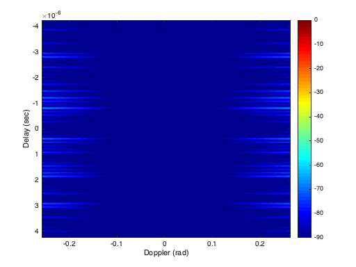
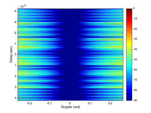
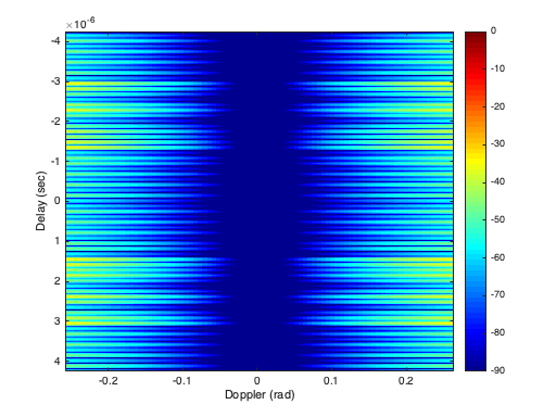
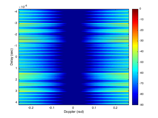
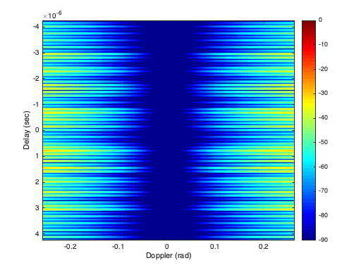
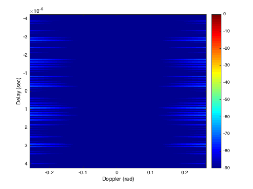
Let us consider the simplest MIMO case, where we have a MIMO radar with collocated transceivers. The paraunitary matrix used in phase coding in this case is , given in (69). In this case, we have two complementary waveform vectors and , and the control of range sidelobes is similar to that in Section III and the three examples considered there are applicable here as well. Here the cross-ambiguity matrix is two-by-two. Figures 2(a)-(d) show the magnitude of the first diagonal element of the cross-ambiguity matrix for (a) the conventional design, (b) the PTM design, (c) the binomial design, and (d) the max-SNR design. As can be seen, the ambiguities corresponding to the PTM, the binomial, and the max SNR design are all essentially delta functions in delay (range) in a Doppler interval around the zero Doppler axis. The plots for the second diagonal elements are identical and are not shown separately. Figures 2(e)-(h) show the magnitude of the first off-diagonal element of the cross-ambiguity matrix for (e) the conventional design, (f) the PTM design, (g) the binomial design, and (h) the max-SNR design. As can be seen, these cross-ambiguity functions corresponding to the PTM, the binomial, and the max-SNR designs all vanish in an interval around the zero Doppler axis. The magnitude of the second off-diagonal element is identical to that of the first off-diagonal elements, because of the cross-ambiguity matrix in (72) has Hermitian symmetry, because of the ordering of Golay waveforms in and is the same.
| (a) Conventional (diagonal) | (b) PTM (diagonal) | (c) Binomial (diagonal) | (d) Max-SNR (diagonal) |
| (e) Conventional (off-diagonal) | (f) PTM (off-diagonal) | (g) Binomial (off-diagonal) | (h) Max-SNR (off-diagonal) |

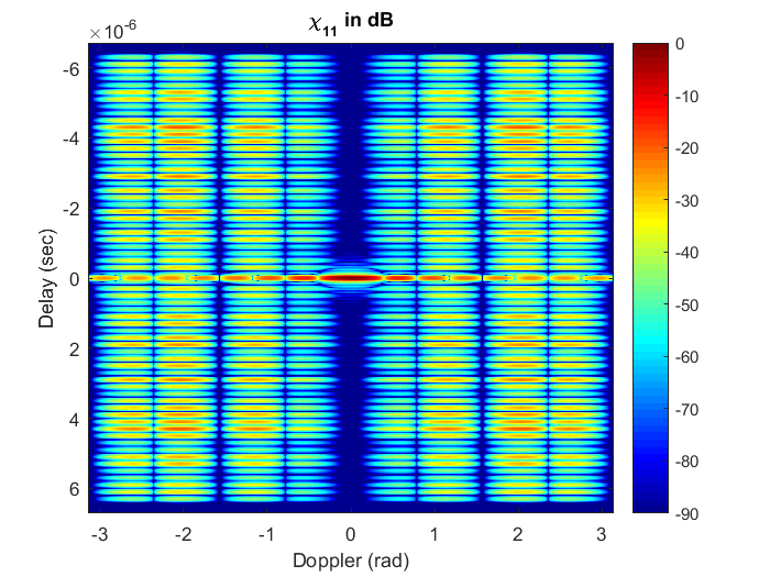


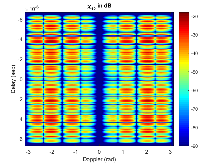

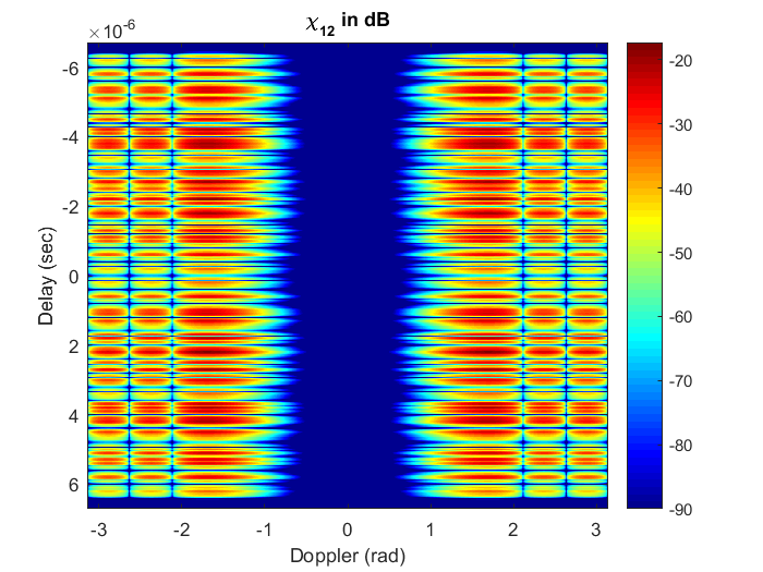
| (a) | (b) | (c) | (d) |
| (e) | (f) | (g) |
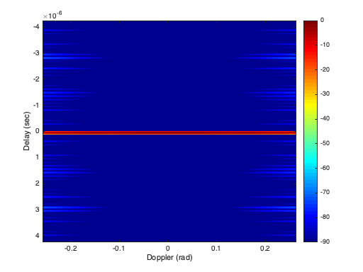
Example 7.
We now consider a MIMO case with collocated transceivers. The paraunitary matrix used in phase coding in this case is , constructed as in (71) with . In this case, we have four complementary waveform vectors , and the control of range sidelobes is similar to that in Section VII and the example presented there is applicable here as well. Here the cross-ambiguity matrix is four-by-four. We wish for the diagonal elements of the cross-ambiguity matrix to look like a delta function in delay (range) in an interval around the zero Doppler axis and for the off-diagonal elements to vanish in an interval around the zero-Doppler axis.
Figures 3(a)-(d) illustrate these effects for the and designed in Example 4 in Section VII. The figure shows the magnitude of the first diagonal element of the cross-ambiguity matrix and the magnitudes of the off-diagonal elements in the upper triangle of the cross-ambiguity matrix. The magnitudes of the other diagonal elements are identical to that of the first diagonal element and hence are not shown separately. The plots for the other off-diagonal elements (in the lower triangle) are identical to the ones shown, because of the Hermitian symmetry of the cross-ambiguity matrix due to the identical ordering of Golay waveforms in and . The plots are shown only in the Doppler interval to highlight sidelobe suppression in range around zero Doppler. Outside this interval the cross-ambiguity elements have large sidelobes, similar to what is observed in previous examples.
IX Conclusion
In this paper we have presented a general approach to the construction of radar transmit-receive pulse trains with cross-ambiguity functions that are free of range sidelobes inside an interval around the zero Doppler axis. The transmit pulse train is constructed by a binary sequence that codes the transmission of a pair of Golay complementary waveforms across time. For the receiver pulse train each waveform is weighted by some integer according to an integer sequence . The range sidelobes of the cross-ambiguity function are shaped by the spectrum of essentially the product of and . By properly choosing the sequences and , the range sidelobes can be significantly reduced inside an interval around the zero Doppler axis. A general way for constructing such sequences has been presented, by specifying the subspace (along with a basis) for sequences that have spectral nulls of a given order around zero Doppler. The output signal-to-noise ratio (SNR) of pairs depends only on the choice of . By jointly designing the transmit-receive sequences , we can maximize SNR subject to achieving a given order of the spectral null. A detailed comparison of two special cases of pulse train design: PTM and Binomial design has been presented.
We also have demonstrated that, for a larger set of complementary sequences, the desired and sequences can be derived from an extension of the joint design of and sequences for a Golay complementary pair.
We have also extend the construction of pairs to multiple-input-multiple-output (MIMO) radar, by designing transmit-receive pairs of paraunitary waveform matrices whose matrix-valued cross-ambiguity function is essentially free of range sidelobes inside a Doppler interval around the zero-Doppler axis.
References
- [1] W. Dang, A. Pezeshki, S. D. Howard, W. Moran, and R. Calderbank, “Coordinating complementary waveforms for sidelobe suppression,” in Conf. Rec. Forty-fifth Asilomar Conf. Signals, Syst., Comput., Pacific Grove, CA, Nov. 6-9 2011, pp. 2096 – 2100.
- [2] W. Dang, A. Pezeshki, S. D. Howard, and W. Moran, “Coordinating complementary waveforms across time and frequency,” in Proc. IEEE Statistical Signal Processing Workshop (SSP), Ann Arbor, MI, Nov. 5-8 2012, pp. 868 – 871.
- [3] N. Levanon and E. Mozeson, Radar Signals. New York: Wiley, 2004.
- [4] R. L. Frank, “Polyphase codes with good nonperiodic correlation properties,” IEEE Trans. Inform. Theory, vol. IT-9, no. 1, pp. 43–45, Jan. 1963.
- [5] R. H. Barker, “Group synchronizing of binary digital sequences,” in Communication Theory, W. Jackson, Ed. London: Butteworth, 1953, pp. 273–287.
- [6] S. W. Golomb and R. A. Scholtz, “Generalized barker sequences,” IEEE Trans. Inform. Theory, vol. IT-11, no. 4, pp. 533–537, Oct. 1965.
- [7] R. C. Heimiller, “Phase shift pulse codes with good periodic correlation properties,” IRE Trans. Inform. Theory, vol. IT-7, no. 4, pp. 254–257, Oct. 1961.
- [8] D. C. Chu, “Polyphase codes with good periodic correlation properties,” IEEE Trans. Inform. Theory, vol. IT-18, pp. 531–532, Jul. 1972.
- [9] M. J. E. Golay, “Complementary series,” IRE Trans. Inform. Theory, vol. 7, no. 2, pp. 82–87, April 1961.
- [10] G. R. Welti, “Quaternary codes for pulsed radar,” IRE Trans. Inform. Theory, vol. IT-6, no. 3, pp. 400–408, June 1960.
- [11] R. Turyn, “Ambiguity functions of complementary sequences,” IEEE Trans. Inform. Theory, vol. IT-9, no. 1, pp. 46–47, Jan. 1963.
- [12] Y. Taki, M. Miyakawa, M. Hatori, and S. Namba, “Even-shift orthogonal sequences,” IEEE Trans. Inform. Theory, vol. IT-15, no. 2, pp. 295–300, Mar. 1969.
- [13] C. C. Tseng and C. L. Liu, “Complementary sets of sequences,” IEEE Trans. Inform. Theory, vol. IT-18, no. 5, pp. 644–652, Sep. 1972.
- [14] R. Sivaswami, “Multiphase complementary codes,” IEEE Trans. Inform. Theory, vol. IT-24, no. 3, pp. 546–552, Sept. 1978.
- [15] R. L. Frank, “Polyphase complementary codes,” IEEE Trans. Inform. Theory, vol. IT-26, no. 6, pp. 641–647, Nov. 1980.
- [16] X. Song, S. Zhou, and P. Willett, “Reducing the waveform cross correlation of MIMO radar with space-time coding,” IEEE Trans. Signal Processing, vol. 58, no. 8, pp. 4213–4224, Aug. 2010.
- [17] A. Pezeshki, A. R. Calderbank, W. Moran, and S. D. Howard, “Doppler resilient Golay complementary waveforms,” IEEE Trans. Inform. Theory, vol. 54, no. 9, pp. 4254–4266, Sep. 2008.
- [18] Y. Chi, A. Pezeshki, and R. Calderbank, “Complementary waveforms for sidelobe suppression and radar polarimetry,” in Principles of Waveform Diversity and Design, M. Wicks, E. Mokole, S. Blunt, R. Schneible, and V. Amuso, Eds. SciTech Publishing, 2011.
- [19] J. P. Allouche and J. Shallit, “The ubiquitous Prouhet-Thue-Morse sequence,” in Sequences and their applications, Proc. SETA’98, T. H. C. Ding and H. Niederreiter, Eds. Springer Verlag, 1999, pp. 1–16.
- [20] J. Tang, N. Zhang, Z. Ma, and B. Tang, “Construction of doppler resilient complete complementary code in MIMO radar,” American Mathematical Monthly, vol. 62, no. 18, pp. 4704–4712, Sep. 2014.
- [21] G. Duggal, S. Vishwakarma, K. V. Mishra, and S. S. Ram, “Doppler-resilient 802.11ad-based ultra-short range automotive radar,” arXiv:1902.01306, May 2019.
- [22] R. Sivaswami, “Self-clutter cancellation and ambiguity properties of subcomplementary sequences,” IEEE Trans. Aerosp. Electron. Syst., vol. AES-18, no. 2, pp. 163–181, Mar. 1982.
- [23] J. Guey and M. R. Bell, “Diversity waveform sets for delay-Doppler imaging,” IEEE Trans. Inform. Theory, vol. 44, no. 4, pp. 1504–1522, Jul. 1998.
- [24] F. F. Kretschmer and B. L. Lewis, “Doppler properties of polyphase coded pulse-compression waveforms,” IEEE Trans. Aerosp. Electron. Syst., vol. AES-19, no. 4, pp. 521–531, April 1983.
- [25] P. B. Rapajik and R. A. Kennedy, “Merit factor based comparison of new polyphase sequences,” IEEE Commun. Lett., vol. 2, no. 10, pp. 269–270, Oct. 1998.
- [26] T. Felhauer, “New class of polyphase pulse compression code with unique characteristics,” Electron. Lett., vol. 28, no. 8, pp. 769–771, Apr. 1992.
- [27] ——, “Design and analysis of new polyphase pulse compression codes,” IEEE Trans. Aerosp. Electron. Syst., vol. AES-30, no. 3, pp. 865–874, Jul. 1994.
- [28] H. A. Khan, Y. Zhang, C. Ji, C. J. Stevens, D. J. Edwards, and D. O’Brien, “Optimizing polyphase sequences for orthogonal netted radar,” IEEE Signal Process. Lett., vol. 13, no. 10, pp. 589–592, Oct. 2006.
- [29] H. Deng, “Polyphase code design for orthogonal netted radar systems,” IEEE Trans. Signal Process., vol. 52, no. 11, pp. 3126–3135, Nov. 2004.
- [30] S. J. Searle and S. D. Howard, “A novel polyphase code for sidelobe suppression,” in Proc. Int. Waveform Diversity and Design Conf., Pisa, Italy, June 2007.
- [31] ——, “A novel nonlinear technique for sidelobe suppression in radar,” in Proc. Int. Conf. Radar Systems, Edinburgh, UK, Oct. 2007.
- [32] S. J. Searle, S. D. Howard, and W. Moran, “On the formation of composite ambiguity functions with frequency separated golay coded pulses,” IEEE Trans. Aeros. and Elctr. Systems, vol. 45, no. 8, pp. 1580–1597, Oct. 2009.
- [33] E. K. P. Chong and S. H. Żak, An Introduction to Optimization, 4th ed. Wiley, 2013.
- [34] P. Stoica and R. Moses, Introduction to spectral analysis. Prentice-Hall, 1997.
- [35] M. Vetterli and J. Kovacevic, Wavelets and Subband Coding. Prentice Hall, 1995.