From far-field to near-field micro- and nanoparticle optical trapping
Abstract
Optical tweezers is a very well-established technique that has developed into a standard tool for trapping and manipulating micron and submicron particles with great success in the last decades. Although the nature of light enforces restrictions on the minimum particle size that can be efficiently trapped due to Abbe’s diffraction limit, scientists have managed to overcome this problem by engineering new devices that exploit near-field effects. Nowadays, metallic nanostructures can be fabricated which, under laser illumination, produce a secondary plasmonic field that does not suffer from the diffraction limit. This advance offers a great improvement in nanoparticle trapping, as it relaxes the trapping requirements compared to conventional optical tweezers. In this work, we review the fundamentals of conventional optical tweezers, the so-called plasmonic tweezers, and related phenomena. Starting from the conception of the idea by Arthur Ashkin until recent improvements and applications, we present some of the challenges faced by these techniques as well as their future perspectives. Emphasis in this review is on the successive improvements of the techniques and the innovative aspects that have been devised to overcome some of the main challenges.
keywords:
optical tweezers, optical forces, particle trapping, plasmonics, self-induced back action effect, surface plasmons1 1. Introduction
Imagine making our fingers one million times smaller and putting them ”inside” the nanoworld. Now, it is easy to imagine that with these fingers we could easily grab things of similar size: dielectric nanoparticles, quantum dots with a DNA strand attached to them, proteins and viruses. More than that, we could have the ability to move them in space. Well, although we cannot modify our fingers, we have found a way to manipulate objects of that size using light!
For more than four centuries, it has been known that light can exert forces on objects [1]. Much later, in 1873, using Maxwell’s famous electromagnetic theory [2], the transfer of momentum from light to illuminated objects was described, resulting in the so-called radiation pressure that leads to objects moving along the direction of light propagation [3]. There were many experiments to follow that confirmed Poynting’s calculations, but all of them were concluding with the fact that these optical forces were so small that it was difficult even to measure them, let alone utilise them in some meaningful application. However, as usually happens with science and technology, the development of techniques to allow this eventually came. Particularly, the birth of lasers around 1960 [4, 5] opened new possibilities and topics for research in the field of light-matter interactions.
As lasers became more and more popular in science exploration, Arthur Ashkin, in 1970, experimentally demonstrated how optical radiation forces exerted by lasers can be used to change the motion of dielectric microparticles. He even managed to trap them by creating a stable optical potential well [6], thus establishing the new research topic that is known today as optical tweezers.
As always, nature follows its own rules, and soon the primary challenge for optical tweezers became apparent, i.e., the diffraction limit. It seemed to be impossible to focus light beyond the constraints imposed by this limit and, consequently, this created a restriction on the smallest size of particle that could be trapped. Subsequently, the next step was the idea to utilise surface plasmons excited on metallic nanostructures to confine light into highly intense optical fields, thus enabling superior trapping performance [7]. The first experimental demonstration of trapping using plasmonic structures was reported by Righini et al. [8] in 2007 and, since then, the field of plasmonic optical tweezers started developing rapidly and opened further scientific avenues for exploration. Numerous implementations arose from the research on optical forces and plasmonics which are mentioned elsewhere [9, 10].
2 2. Conventional Optical Tweezers
The Nobel Prize in Physics 2018 was awarded (50%) to Arthur Ashkin ”for the optical tweezers and their application to biological systems”. The whole research field started when Ashkin calculated that ”a power of cw argon laser light at focussed on a lossless dielectric sphere of radius and density gives a radiation pressure force , where , the fraction of light effectively reflected back, is assumed to be of order 0.1. The acceleration times the acceleration of gravity” [6]. In the same work, he demonstrated the first experimental approach to test his calculations on transparent, micron-sized latex spheres in liquids and gas. Indeed, he found that the radiation pressure exerted on the particles from a focussed laser light beam was able to accelerate them along the direction of the beam and the measured velocities of the accelerated particles were in very good agreement with the theoretical predictions.
Ashkin then went even further and demonstrated trapping of particles using one laser beam and the wall of a glass cell, as well as using two counter-propagating beams with the same characteristics [6]. However, a few years later, Ashkin et al. [11], reported trapping of dielectric particles (10 m - 25 nm) using a single beam by focussing argon-laser light at 514.5 nm through a high numerical aperture objective lens (). The achievement of this is attributed to the existence of a force additional to that caused by the radiation pressure (from now on called the scattering force) which originates from the axial beam intensity gradient. It then becomes apparent that, whereas the scattering force depends on the optical intensity and has the direction of the incident beam, the gradient force depends on the intensity gradient and is directed along it from low to high intensities. This allows for optical trapping by balancing these two forces.
The theoretical mechanism that explains this observation, depends on the relative size of the particle (radius, ) in respect to the wavelength of the laser light (). For , ray optics can be used and the reflection and transmission of the beam from the particle can give rise to the two forces. For , Rayleigh scattering is assumed and the particle is treated like a dipole in an external electromagnetic field. The two regimes are analysed below. Finally, there is the intermediate regime where the particle size is of the same order of magnitude as the wavelength. In this case, the approximations mentioned above cannot be used and, in order to evaluate the forces arising, Maxwell’s stress tensor, which relates the interactions between electromagnetic forces and mechanical momentum [9, 12], should be used. To handle this complicated mathematical analysis different algorithms have been established, such as the transition matrix (T-matrix) method [13] and the discrete dipole approximation (DDA) [14]. Due to its complexity this regime is not analysed here.
2.1 Ray optics approximation ( )
We assume spherical particles of higher refractive index than their surrounding environment, being in a liquid solution and undergoing Brownian motion. As soon as a particle, randomly moving, enters the light beam, a small fraction of light is reflected off the surface of the particle and most of it is refracted on passing through the particle (assuming no absorption). Light carries momentum and, since refraction is a light-matter interaction phenomenon, there is a momentum transfer from the photons to the particle. As is known from geometrical optics, the path of the light changes due to the refraction, resulting in a change in the momentum of the photons. Obviously, from conservation of momentum for the light-particle system, there should also be a change in the momentum of the particle and this creates a force acting on the particle, . To get a first insight, we can initially assume that there is no reflection and part of the beam is refracted inside the sphere as shown in Figure 1a. According to the work done in [15, 16], the magnitude of the force on the particle due to the momentum change of a single ray is given by
| (1) |
where is the refractive index of the particle, is the speed of light and is the power of the incident ray. Since the Gaussian beam has a radial intensity profile, the rays closer to the centre of the beam carry higher power (i.e., intensity); thus, the resultant force from ray 2 () is stronger than that from ray 1 (), as shown in Figure 1a.
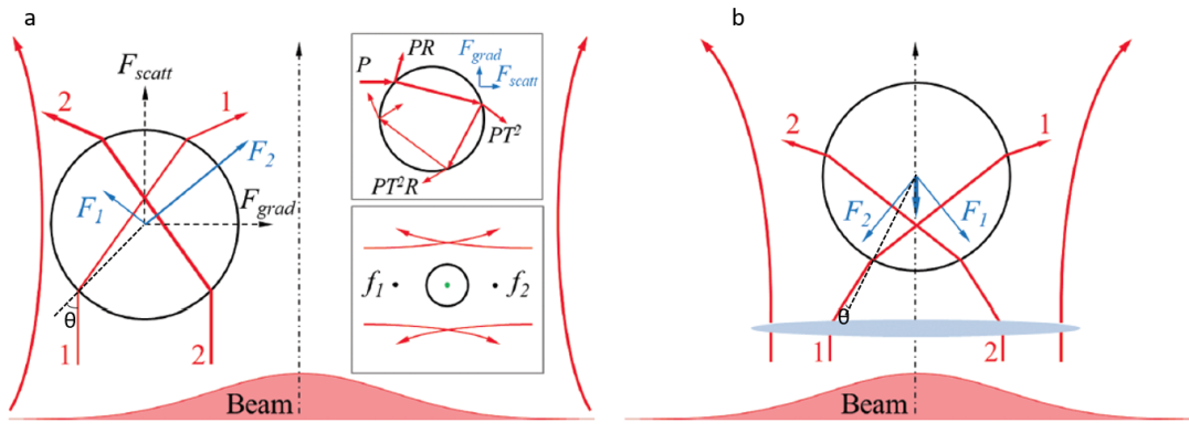
The forces acting on the particle can be reduced into a longitudinal component parallel to the incident ray and a transversal one perpendicular to it. As shown in the figure, the longitudinal components of the two forces add up to create a scattering force, whereas the transversal components subtract leading to a gradient force towards the beam’s higher intensity, thus moving the particle to the centre of the Gaussian beam and along its axis. Note that, for particles with a lower refractive index than the surroundings, the forces reverse and the particle moves away from the centre of the beam.
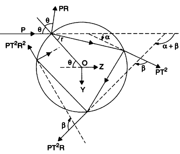
If we want to describe the process in a more accurate and mathematically rigorous way, we have to take into account multiple internal reflections and refractions of the rays, as shown in the top inset of Figure 1a and Figure 2. The forces exerted on a particle were first calculated by Roosen [18] by considering Fresnel’s reflection () and transmission () coefficients. For a detailed derivation see [19, 20]. The resulting forces are:
| (2) |
and
| (3) |
where the sum is over all rays interacting with the particle, and and are the incidence and refraction angles, respectively, as shown in Figure 2. The terms in the square brackets are the dimensionless trapping efficiencies, and , and account for the efficiency of momentum transfer from the light ray to the particle. We also define the total trapping efficiency of the ray as . The Fresnel coefficients, and , depend on the polarisation of the incident rays. Therefore, the trapping efficiencies and the trapping forces will also be polarisation dependent.
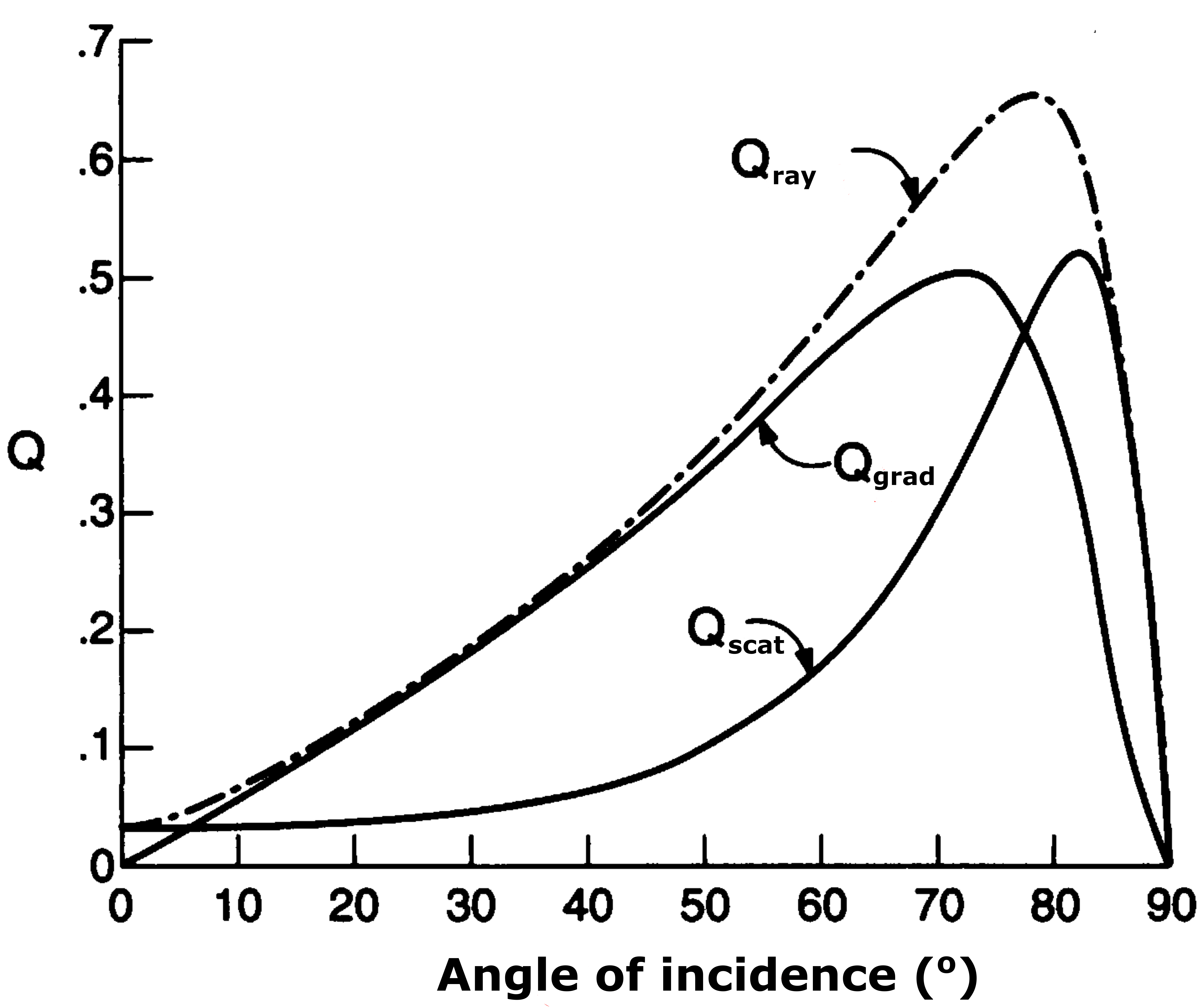
In Figure 3, the trapping efficiencies as a function of the ray’s incident angle are plotted for circularly polarised light hitting a glass sphere in water . We can see that, for incident angles smaller than , the gradient force dominates, but as the incident angle increases, the scattering force becomes significant. This means that, for unfocussed or slightly focussed beams that have a small convergence angle, inevitably most of the rays (taking into account the Gaussian beam profile) will hit the surface of the particle with a large incident angle, , as shown in Figure 1a, thereby pushing the particle away. On the contrary, beams that are tightly focussed under a high NA objective lens, cause the rays to hit the surface of the particle with small incident angles (Figure 1b). As a result, the gradient forces strongly dominate over the scattering ones and a stable trap can be established, as Ashkin et al. experimentally demonstrated [11]. Note that, in this case, the longitudinal component of the resulting forces always points towards the beam’s focal point, as shown in Figure 1, leading to particle trapping close to the focal point. Ashkin’s calculations [19] confirmed that, in order to create strong, single-beam traps, high convergence angles are required. For convergence angles smaller than , single-beam trapping is impossible. Instead, we can use two counter-propagating beams with the same characteristics, as shown in the bottom inset of Figure 1a, to cancel out the scattering forces [6].
2.2 Dipole approximation
In this case, the electric field that the particle experiences is approximately spatially constant and, assuming a dielectric particle, we can treat the entire particle as a collection of induced point dipoles in a homogeneous electric field. Early theoretical work on radiation forces and scattering effects for subwavelength dielectric media can be found in [15, 21]. Based on this work and the electromagnetic theory for electromagnetically induced dipoles, we can describe the optical forces and the trapping potential that arises.
The situation for a homogeneous particle can be briefly described as follows111The analysis presented is taken from [20].: The oscillating electromagnetic field from the laser beam causes each of the particle’s point dipoles to have a dipole moment
| (4) |
where is the electric field and is the polarizability of the particle, given by the Clausius-Mossotti relation
| (5) |
Here, is the particle’s radius, is the vacuum dielectric permittivity, and is the particle’s dielectric permittivity. The external field causes the dipoles to oscillate and, thus, radiate. Now, we have to take into account the dipole’s interaction not only with the external electromagnetic field, but with its own induced scattered field as well. For that reason, the effective polarizability, , is introduced as a radiative reaction correction to the intrinsic polarizability of the particle [20] and it is given by
| (6) |
with being the vacuum wavenumber.
Similarly, in order to calculate the forces acting on all the dipoles, we have to take into account the Lorentz force from the external field and the radiation forces arising from the dipoles themselves. It is also convenient to calculate the time-averaged total force since it is the one that is observable (electromagnetic fields oscillate on the order of Hz which is very fast). Rigorous calculations have been done in [22, 20, 17]. According to these works, the resulting, time-averaged force acting on a dipole is given by
| (7) |
where is the real part of the effective polarizability, is the angular frequency, is the extinction cross-section, i.e., the active area of the particle that causes part of the energy of the incident electromagnetic wave to be extinguished due to scattering and absorption from the particle. It, therefore, indicates the rate of energy loss from the incident wave. is the time-averaged real part of the Poynting vector of the incident wave
| (8) |
In Equation (7), we see that the force acting on a dipole consists of three terms; the third term is called the spin-curl force and is related to polarisation gradients in the electromagnetic field that arise when the polarisation is inhomogeneous. Using a defined polarisation of the incident beam, this term has a small value compared to the other two terms and that is why we usually neglect it in optical trapping experiments. The second term is the scattering force pointing in the direction of the Poynting vector, , and arises from absorption and scattering phenomena that cause momentum transfer from the field to the particle. The first term is the gradient force and depends on the particle’s polarizability and the intensity gradient of the electric field. We know that and so the gradient force takes the form
| (9) |
Equation (9) tells us that, for particles with positive polarizability (i.e., a higher refractive index than its surrounding) this force acts towards the direction of the field’s higher intensity, i.e., the focal point. At the focal point of a Gaussian beam with a beam waist, , and radial coordinate, , we can approximate the intensity distribution as
| (10) |
and, for small radial displacements, we can Taylor expand to get
| (11) |
and substitute into Equation (9). Thence,
| (12) |
By comparing with the restoring force of the classical harmonic oscillator, , we get the trapping constant
| (13) |
and, by integrating Equation (12), we get the trapping potential
| (14) |
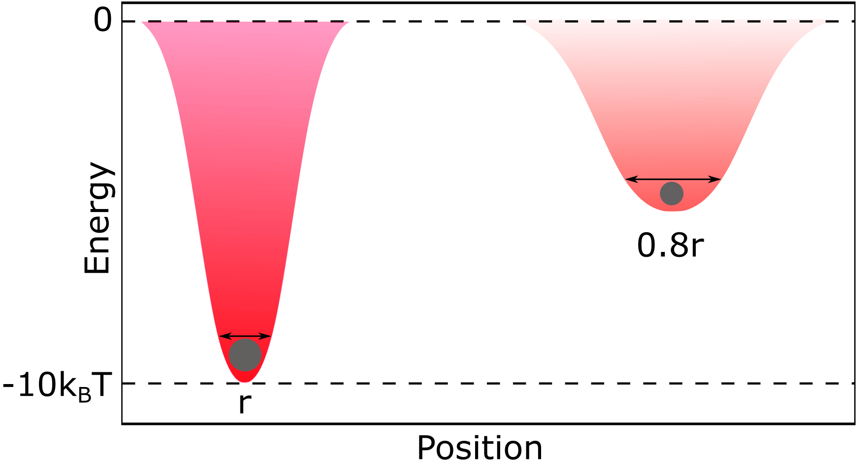
which is plotted in Figure 4. Note that similar analysis can be used in order to obtain the potential and the trapping constant along the axial direction.
Let us now present the main limitation of conventional optical tweezers. Ashkin et al. [11] did some rough calculations and showed that, in order to create a stable optical trap, resisting the Brownian motion of particles in a liquid environment, a potential well as deep as is required, where is the temperature in Kelvin. Although in some cases this is easy to achieve, for subwavelength particles, as they become smaller in size, the gradient force scales down very quickly, making it impossible to satisfy this requirement. According to Eqs. (5) and (6), , which means that, when the radius of the particle decreases by a factor of 10, the polarizability of the particle and, consequently, the gradient force (Equation (9)) decrease by a factor of 1,000. The trapping potential is no longer deep and tight enough to hold the particle (Figure 4) and the trap is inefficient. We can use Equations 5, 6 and 13 to calculate the change in the trapping stiffness if the particle has a radius of :
| (15) |
Calculations show that for nm, there is a decrease in the trapping stiffness when the particle’s radius decreases to . From Equation (13) we see that, in order to compensate for this effect and increase the trapping constant and the gradient force, we can either increase the intensity of the incident field () or focus tighter (). However, even though in some cases it is experimentally possible to increase the intensity of the field by a factor of 1,000, the heat accumulation will be huge and eventually destroy the particle, especially if it is a biological sample. On the other hand, the diffraction limit allows focussing of the beam to a certain spot size and this sets a minimum on the particle size that can be successfully trapped. Additional to these limitations, as the particle becomes smaller, the viscous drag reduces and the particle undergoes more intense Brownian motion, making it easier for it to escape from the trap.
3 3. Plasmonic Optical Tweezers
Recent advances in the field of optics and nano-optics have helped to overcome the diffraction limit problem by using evanescent fields instead of propagating ones; these have the intrinsic property of confinement beyond the diffraction limit. A detailed analysis can be found in [23, 24]. The current trend is to use metallic nanostructures (see [25] for a recent review on different platforms) in which surface plasmons can be excited at resonant frequencies and that concentrate the electric field to create highly intense fields, thereby significantly increasing the trapping potential depth that a nanoparticle may experience.
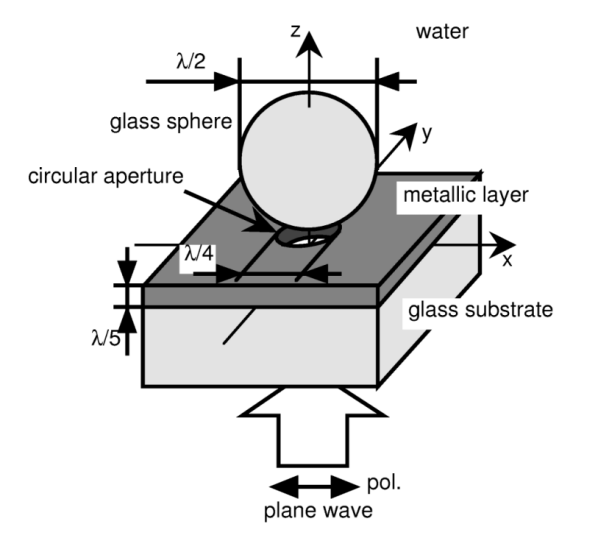
In 1992, Kawata et al. were the first to demonstrate ”Movement of micrometer-sized particles in the evanescent field of a laser beam” [26] and, in 1997, Novotny et al. were the first to theoretically propose and calculate optical trapping at the nanoscale, using enhanced evanescent fields from a laser-illuminated metallic nanotip [7]. Okamoto et al., around the same time, did similar work, but used a metallic nanoaperture instead of a tip [27]. Figure 5 shows their proposed geometrical model.
The advantage of using this kind of configuration comes from the fact that the incident field is no longer ”responsible” for creating the trapping potential, but rather for exciting the surface plasmons (SP) on the metal/dielectric interface. The SPs, in turn, create the strong evanescent field that is ”responsible” for the trapping potential. The main benefit of trapping using an evanescent field is that, by nature, it has a very high field gradient, thus exerting a large trapping force (see Equation (9)) with no need to increase the incident intensity, thereby leading to a reduction of radiation damage to the sample. In other words, superior trapping conditions can be achieved with much lower illumination power compared to the conventional optical tweezers.
It was then just a matter of time for the first experimentally demonstrated plasmonic optical tweezers to be reported. In 2007, Righini et al., using a geometry of total internal reflection similar to the one shown in Figure 6a, and a pattern consisting of 4.8 m-diameter gold discs fabricated on glass, performed multiple trapping of 4.88 m polystyrene colloids [8]. Note that the laser beam was unfocussed, with a waist of about 100 m and the intensity was more than 10 times lower than that required for conventional optical tweezers with similar characteristics. Theoretical work had been done earlier in order to study the forces arising in such a configuration [28]. Also, in earlier experimental work, the authors used a photonic force microscope to measure the plasmon radiation forces acting on polystyrene beads at the localised surface plasmon resonance. They reported forces 40 times stronger than those obtained in the absence of SP excitation [29].
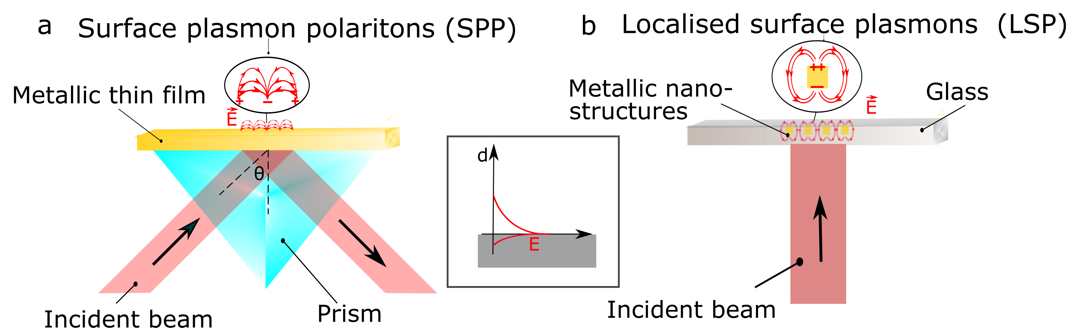
Now, it is important to mention the two distinct types of surface plasmons. Surface plasmon polaritons (SPP) are propagating electromagnetic surface waves that appear at the metal/dielectric interface due to the motion of the metal’s free electrons driven by the incident electromagnetic field. They are evanescent modes and, thus, they produce localised fields with a high intensity decaying exponentially away from the metal surface. Due to the very large intensity gradient, they exert strong gradient forces on the trapped particles (see Equation (9)), thereby producing stable traps. However, because SPPs are pure evanescent modes, direct coupling to propagating light is not possible and, in order to excite them, a different geometrical approach is required. The most common experimental method is the Kretschmann configuration, which is shown in Figure 6a. Light is coupled into SPPs under total internal reflection in order to compensate for the light momentum mismatch. The crucial parameter in this configuration is the angle of incidence, , which controls both the scattering and the gradient force, allowing for tuning of the total trapping force.
In contrast, localised surface plasmons (LSP) are related to the bound electrons that are present near to nanoapertures or nanoparticles much smaller than the wavelength of the electromagnetic field. Bound electrons are susceptible to a damping oscillation due to the nucleus attraction and, as a result, they have a characteristic resonance frequency, unlike SPPs that can be excited over a wide range of frequencies. The benefits of LSPs are that they can directly couple to propagating light and their resonance frequency can be tuned by changing the size and the shape of the nanoaperture/nanoparticle (Figure 6 b). In a theoretical work done on LSPs, the dramatic dependence of the strength of the excited evanescent field on the frequency of the incident electromagnetic field was presented [28]. Detailed mathematical analysis on the excitation of surface plasmons and the forces arising can be found in Ref. [20] and [30].
To date, many different configurations have been reported using SPs for efficient trapping of subwavelength particles, such as plasmonic nanodots [31], nano-antennas [32], nanocavities [33] and nano-apertures of different shapes and sizes [34, 35], reporting very low incident power. Note that, in these cases, rigorous calculations need to be done beforehand, in order to determine crucial parameters such as resonance wavelength and polarisation in compliance with the plasmonic field excitation requirements. Additionally, the fabrication of those nanostructures can also be a challenging task. The most popular techniques to fabricate structures of these sizes is focussed ion beam (FIB) milling and electron beam lithography (EBL), with a resolution of about 10 nm.
To conclude, we emphasize that the principle of trapping using surface plasmons is the same as in the case of conventional optical tweezers, in the sense that again we have to find the appropriate balance between the gradient and the scattering force in order to achieve a stable trap. The improvement comes from the fact that, in plasmonic optical tweezers, the excited plasmonic field offers stronger gradient forces and a better control over them, as explained above. However, due to the conductive nature of metals, the excitation of SPs is connected with heat induction and dissipation to the surrounding environment and these can increase the destabilisation forces.
3.1 Self-Induced Back Action Effect
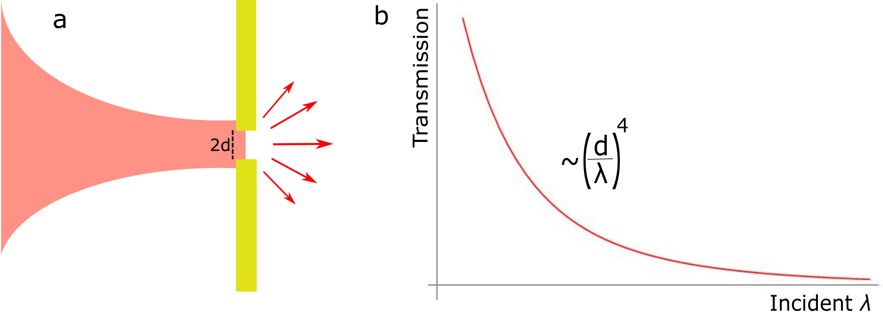
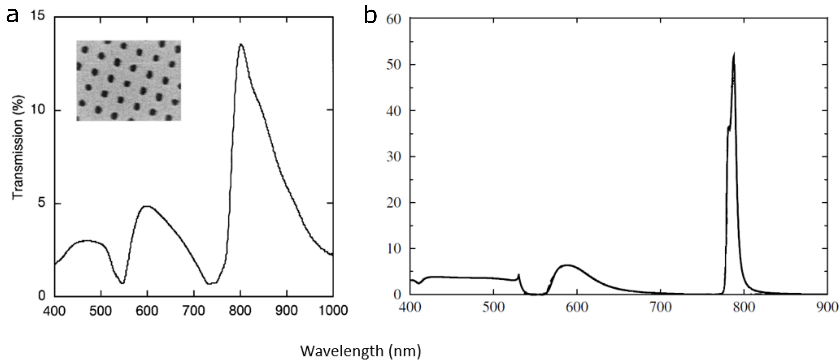
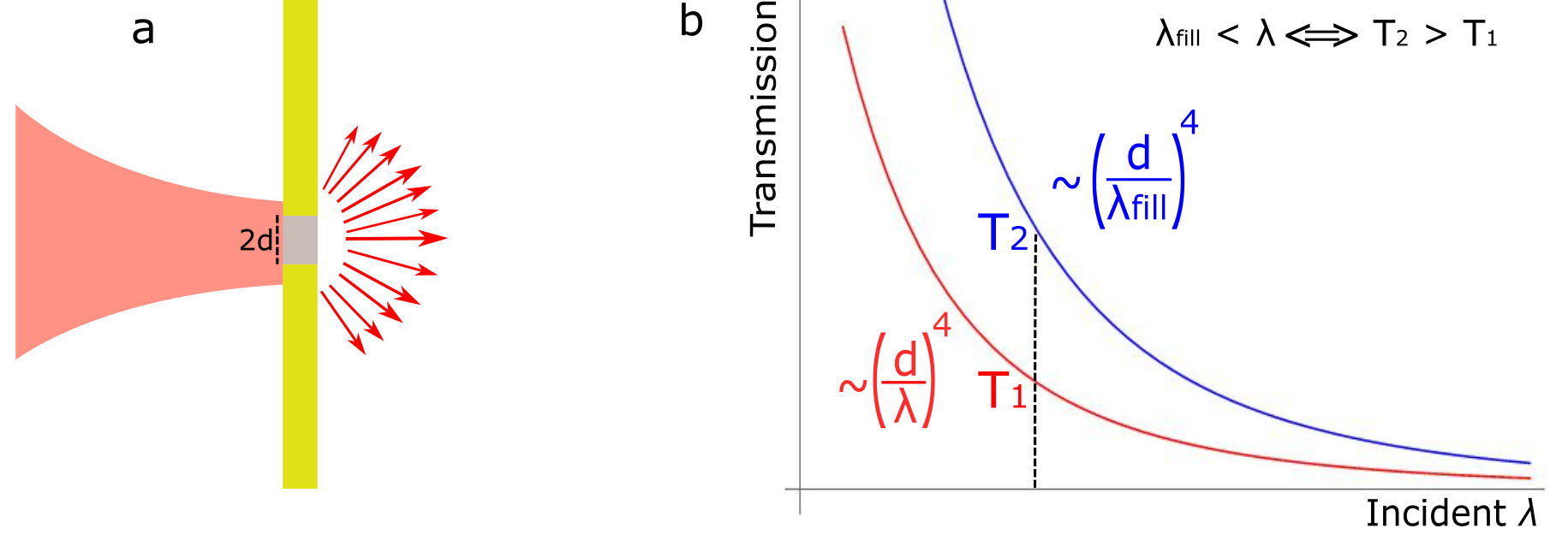
The diffraction and transmission of light through a single, subwavelength-sized circular hole on a metallic surface was first theoretically studied in 1944 by Bethe [36]. Assuming a perfectly conducting and infinitely thin material, Bethe calculated that the transmitted light would scale as , where is the radius of the hole and the wavelength of the incident light, as illustrated in Figure 7. In 1998, the remarkable phenomenon of the extraordinary transmission of light was experimentally observed by Ebbesen et al. [37], when they studied the effects of the geometrical characteristics of an array of tiny holes, drilled on different metallic films, on the transmission of light. In that work, UV-Vis-NIR spectrophotometry of the array was performed and it revealed the existence of maxima in the transmission intensity, see Figure 8a, with much higher values than predicted from Bethe’s theory. These maxima could not be explained simply by diffraction theory and they were associated with the resonant frequencies of the excited surface plasmons of the metal. A detailed theoretical explanation of this observation was provided a few years later [38, 39], where the calculated transmission maxima were in very good agreement with the experiment (Figure 8b).
In addition, in his theoretical work, Abajo investigated the case of filling the nano-hole with a dielectric material of high refractive index (Si). He found out that the transmission cross-section at the resonance frequency was almost three times higher than without the filling, leading to increased transmission [39]. The increase of the refractive index at the nano-hole causes the wavelength of the light to decrease:
| (16) |
A consequence of this effect is that, according to Bethe’s theory, the transmission of light through the subwavelength aperture increases, a phenomenon also known as dielectric loading. Figure 9 shows how the wavelength shift causes a significant increase in the transmission of light.
As mentioned in the previous section, at around the same time, the use of plasmonics for enhanced optical trapping had started to attract attention and, despite how promising they might seem for trapping subwavelength particles, it became apparent that their use is limited to particles with a minimum diameter around 100 nm due to photothermal effects [41].
It was the combination of these two different studies on plasmonics that brought the realisation that the resonance frequency of the excited plasmonic field is very sensitive to changes of the local refractive index. Thus, by proper engineering of the plasmonic structure, the trapped particle itself could actively contribute to its own trapping potential in a dynamical way [42]. This plasmonic structure - particle interaction promised high tunability of the trapping potential, which was no longer a static. This gave rise to the self-induced back action (SIBA) effect and the first experimental trapping utilising this effect, where polystyrene spheres of 100 and 50 nm size were successfully trapped with incident powers as low as 0.7 and 1.9 mW, respectively [43], pushing further the boundaries of plasmonic nanotweezers.
A comprehensive mathematical analysis of the SIBA effect has been done by Neumeier et al. [44], for a small dielectric particle trapped in a plasmonic nanocavity. They demonstrated the additional restoring forces that act on the particle as it tries to escape from the trap. Below, we present the basic principle of the SIBA effect following the analysis done in [41].
The gradient force experienced by a nanosphere with radius of the incident light, is given by Equation (9), as mentioned previously. If we assume small displacements of the particle from the centre of the trap (), then its equation of motion inside the trap is given by
| (17) |
where is the viscous damping [45], assuming that the particle exists in a liquid environment, is the stiffness of the trap, indicating how strongly the particle is confined in the trap, and represents thermal fluctuations [46]. Due to the coupling between the cavity and the particle, the latter causes the plasmon resonance frequency of the cavity to shift by , where indicates the frequency dependence on the particle’s position. Then, for a cavity with mode volume, , and intensity profile, , normalised to 1 for maximum intensity, the perturbation theory for shifts much smaller than the cavity eigenfrequency, , yields
| (18) |
with being the effective polarizability, from Equation (6). Note that the magnitude of the shift strongly depends on the relative size of the particle and the cavity and, as expected from Equation (18), a decrease in the particle’s size (decrease in , see Eqs. (5), (6)), decreases the magnitude of the shift [47].
Now, for incident laser frequency, , and being the cavity detuning, the intracavity intensity, , is given, on Taylor expansion, as
| (19) |
where is the cavity linewidth and is the empty cavity profile.
As can been seen from Equation (19), the intensity of light inside the cavity, to a first order approximation, is given by the term related to the intensity of the empty cavity, plus the one related to the frequency shift caused by the presence of the particle. This second term is the one that causes the SIBA effect and modifies the optical potential. Following Equation (19), we can also write the total trapping stiffness, , as
| (20) |
where is constant and depends on the cavity resonance profile and is a function of the particle’s displacement. According to Neumeir et al., in order to optimise , the cavity has to be constructed such that the back-action parameter, , is maximised [44]. This means that, while the particle is trapped in the centre of the trap, the resonance shift is such that the photon flux from the cavity is less than the maximum possible. As a consequence, when the particle moves away from the centre of the trap, the resonance shift causes the photon flux to increase and, thus, the intensity of the transmitted light increases. From Equation (9) an increase to the intensity leads to an increase to the gradient force, which restores the particle back to the centre of the trap. Then, the photon flux and the intensity decrease and, again, the particle tends to move away from the trap centre. This kind of feedback is referred to as ”optomechanical coupling” because there is a continuous response between light and mechanical motion. The field of optomechanics in plasmonics is rather unexplored and, to our knowledge, there is only one work that reports an optomechanical coupling constant [41]. This optomechanical coupling not only relaxes the requirements for high power trapping, but also prevents the sample from overheating since most of the time the particle is trapped using a low intensity. It remains open to exploration to find ways to increase the optomechanical coupling constant and to achieve even higher particle confinement and motion transduction.
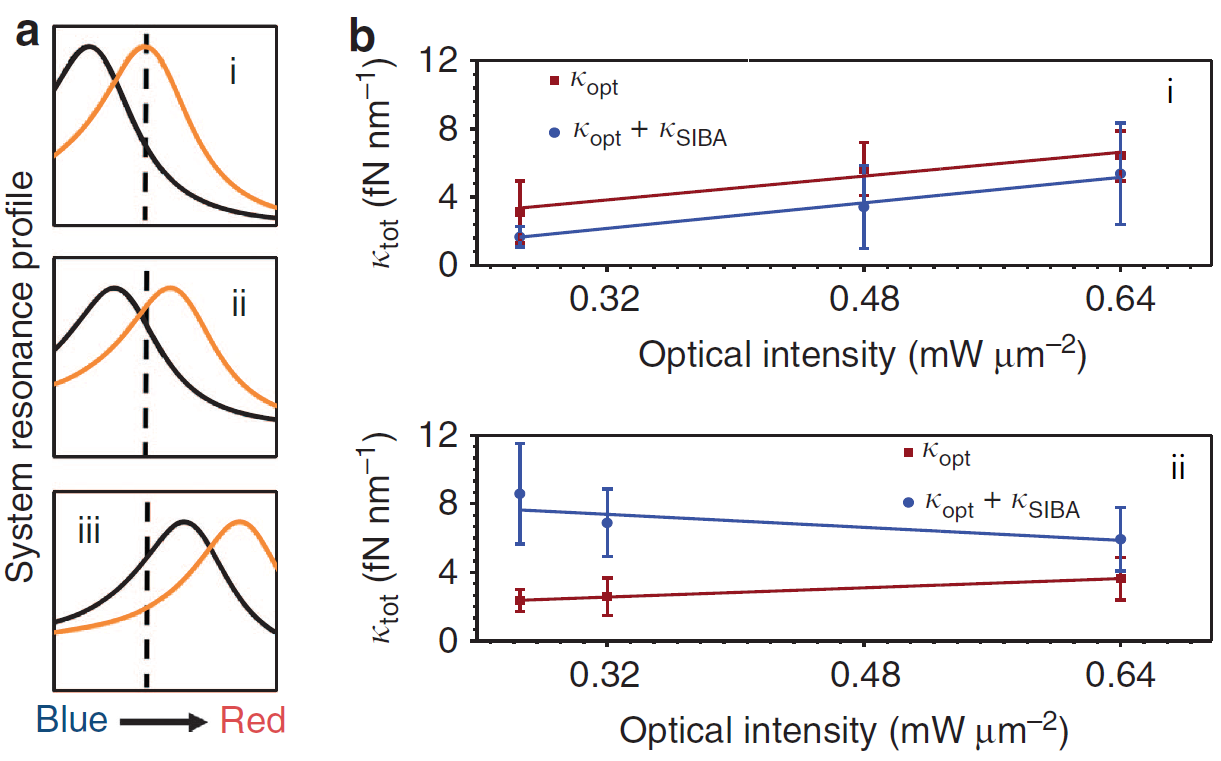
In Figure 10a, the vertical dashed line represents the excitation laser wavelength, the black lineshape is the empty cavity mode resonance, and the orange is the shifted one due to particle trapping. In the first case (Figure 10a(i), blue-shifted) the cavity resonance is set to be blue-detuned from the excitation laser, such that when the particle is trapped, the resonance red-shift increases the photon flux to the maximum value and the gradient force reaches a maximum. However, when the particle moves away from the centre of the trap, the lineshape blue shifts towards the empty cavity resonance and the intensity decreases. In order to increase the gradient force, the power of the laser has to, externally, be increased, thus, it is not the most efficient scenario for trapping. In the case where the empty mode resonance is slightly blue-detuned (Figure 10a(ii), resonance), the red-shifting due to a trapping event creates a symmetrical lineshape around the laser wavelength. As the particle tries to escape from the trap, the resonance moves towards the empty mode value and causes an increase in the photon flux and the light intensity of light, thus increasing the gradient force. Finally, in the case where the empty cavity resonance is designed to be red-detuned from the excitation laser (Figure 10a(iii), red-shifted), the trapped object further red-shifts the resonance, leading to significant reduction in the intensity and the gradient force. In this configuration, the trapping becomes very inefficient and an increase to the laser power is necessary to keep the particle in the trap.
The intensity required to keep the particle efficiently in the trap is less in the second case where the SIBA effect contributes to an increase in the total trapping stiffness. This was also experimentally observed for the first time by Mestres et al. [41]. Figure 10b shows the experimental data that confirm the superior trapping efficiency of a plasmonic cavity, designed to be slightly blue-detuned from the excitation wavelength (Figure 10a(ii), b(ii)). The remarkable effect of SIBA is now apparent and, by proper design of the plasmonic structure, we can have a larger trapping stiffness at a lower laser power, thereby reducing heat transfer to the specimen.
4 4. Conclusions and Future Perspectives
There are many open questions and challenges to overcome in order to optimise the plasmonic tweezers and make them able to efficiently trap particles in the range of less than 10 nm and biological samples such as proteins, viruses and DNA. In our opinion, one of these important questions is whether it is possible to enhance the SIBA effect itself so that we achieve even better optomechanical response of the system and superior trapping performance.
It is amazing to see how a simple idea can be transformed into a powerful technique for controlling matter, finally leading to the awarding of a Nobel Prize. But it is even more amazing to see people devoting themselves to solving a particular problem and pushing the boundaries of science into the unknown to make it possible. Optical tweezers-based platforms are today, thanks to all these scientistific efforts, widely used in the fields of physics [48], biomedicine [49, 50, 51], chemistry [52] and many more. In many cases, it serves as a tool to manipulate matter while doing other measurements, for example Raman spectroscopy of biological samples [53, 54, 55]. This gives us a great advantage towards the exploration of the nanoworld and the advancement of the nanotechnologies. What is next?
Acknowledgements
The authors would like to thank Okinawa Institute of Science and Technology Graduate University for funding, and D. G. Kotsifaki, P. Reece, P. Okada, F. Pauly, and G. Tkachenko for constructive comments.
References
- Kepler [1619] J. Kepler. De cometis libelli tres. Typis Andreæ Apergeri, sumptibus Sebastiani Mylii bibliopolæ Augustani, 1619. URL https://books.google.co.jp/books?id=5Z1BQAAACAAJ.
- Maxwell [1873] J.C. Maxwell. A Treatise on Electricity and Magnetism, volume 2. Oxford, 1873.
- Poynting and William [1884] J. H. Poynting and S. J.XV William. On the transfer of energy in the electromagnetic field. Phil. Trans. R. Soc., 175, 1884.
- Maiman [1960] T. H. Maiman. Stimulated optical radiation in ruby. Nature, 187(4736):493–494, 1960. ISSN 1476-4687. 10.1038/187493a0. URL https://doi.org/10.1038/187493a0.
- Schawlow and Townes [1958] A. L. Schawlow and C. H. Townes. Infrared and optical masers. Physical Review, 112(6):1940–1949, 1958. ISSN 0031-899X. 10.1103/PhysRev.112.1940.
- Ashkin [1970] A. Ashkin. Acceleration and trapping of particles by radiation pessure. Phys. Rev. Lett., 24(4):156–159, 1970. ISSN 0031-9007. 10.1103/PhysRevLett.24.156.
- Novotny et al. [1997] Lukas Novotny, Randy X. Bian, and X. Sunney Xie. Theory of nanometric optical tweezers. Phys. Rev. Lett., 79(4):645–648, 1997. 10.1103/PhysRevLett.79.645. URL https://link.aps.org/doi/10.1103/PhysRevLett.79.645.
- Righini et al. [2007] Maurizio Righini, Anna S. Zelenina, Christian Girard, and Romain Quidant. Parallel and selective trapping in a patterned plasmonic landscape. Nat. Photonics, 3(7):477–480, 2007. ISSN 1745-2473 1745-2481. 10.1038/nphys624.
- Marago et al. [2013] O. M. Marago, P. H. Jones, P. G. Gucciardi, G. Volpe, and A. C. Ferrari. Optical trapping and manipulation of nanostructures. Nat. Nanotechnol., 8(11):807–19, 2013. ISSN 1748-3395 (Electronic) 1748-3387 (Linking). 10.1038/nnano.2013.208. URL https://www.ncbi.nlm.nih.gov/pubmed/24202536.
- Juan et al. [2011] Mathieu L. Juan, Maurizio Righini, and Romain Quidant. Plasmon nano-optical tweezers. Nature Photon., 5(6):349–356, 2011. ISSN 1749-4885 1749-4893. 10.1038/nphoton.2011.56.
- Ashkin et al. [1986] A. Ashkin, J. M. Dziedzic, J. E. Bjorkholm, and Steven Chu. Observation of a single-beam gradient force optical trap for dielectric particles. Opt. Lett., 11(5):288–290, 1986. 10.1364/OL.11.000288. URL http://ol.osa.org/abstract.cfm?URI=ol-11-5-288.
- Pfeifer et al. [2007] Robert N. C. Pfeifer, Timo A. Nieminen, Norman R. Heckenberg, and Halina Rubinsztein-Dunlop. Colloquium: Momentum of an electromagnetic wave in dielectric media. Rev. Mod. Phys., 79:1197–1216, Oct 2007. 10.1103/RevModPhys.79.1197. URL https://link.aps.org/doi/10.1103/RevModPhys.79.1197.
- Borghese et al. [2007] Ferdinando Borghese, Paolo Denti, and Rosalba Saija. Scattering from model nonspherical particles. Springer-Verlag Berlin Heidelberg, 2007. 10.1007/978-3-540-37414-5.
- Draine and Flatau [1994] Bruce T. Draine and Piotr J. Flatau. Discrete-dipole approximation for scattering calculations. Journal of the Optical Society of America A, 11(4):1491–1499, 1994. 10.1364/JOSAA.11.001491. URL http://josaa.osa.org/abstract.cfm?URI=josaa-11-4-1491.
- Gordon [1973] James P. Gordon. Radiation forces and momenta in dielectric media. Phys. Rev. A, 8(1):14–21, 1973. ISSN 0556-2791. 10.1103/PhysRevA.8.14.
- Ashkin and Dziedzic [1973] A. Ashkin and J. M. Dziedzic. Radiation pressure on a free liquid surface. Phys. Rev. Lett., 30(4):139–142, 1973. ISSN 0031-9007. 10.1103/PhysRevLett.30.139.
- Bradac [2018] Carlo Bradac. Nanoscale optical trapping: A review. Adv. Opt. Mater., 6(12), 2018. ISSN 21951071. 10.1002/adom.201800005.
- Roosen [1979] Gérald Roosen. La lévitation optique de sphères. Can. J. Phys., 57(9):1260–1279, 1979. ISSN 0008-4204. 10.1139/p79-175. URL https://doi.org/10.1139/p79-175.
- Ashkin [1992] A. Ashkin. Forces of a single-beam gradient laser trap on a dielectric sphere in the ray optics regime. Biophys. J., 61(2):569–582, 1992. ISSN 0006-3495. https://doi.org/10.1016/S0006-3495(92)81860-X. URL http://www.sciencedirect.com/science/article/pii/S000634959281860X.
- Jones et al. [2015] Philip Jones, Onofrio M. Marago, and Giovanni Volpe. Optical Tweezers: Principles & Applications. Cambridge University Press, Cambridge, 2015. ISBN 9781107051164.
- M. Purcell and R. Pennypacker [1973] Edward M. Purcell and Carlton R. Pennypacker. Scattering and absorption of light by nonspherical dielectric grains. Astrophys. J., 186:705–714, 1973. 10.1086/152538.
- Spesyvtseva and Dholakia [2016] Susan E. Skelton Spesyvtseva and Kishan Dholakia. Trapping in a material world. ACS Photonics, 3(5):719–736, 2016. 10.1021/acsphotonics.6b00023. URL https://doi.org/10.1021/acsphotonics.6b00023.
- Vigoureux and Courjon [1992] J. M. Vigoureux and D. Courjon. Detection of nonradiative fields in light of the heisenberg uncertainty principle and the rayleigh criterion. Appl. Opt., 31(16):3170–3177, Jun 1992. 10.1364/AO.31.003170. URL http://ao.osa.org/abstract.cfm?URI=ao-31-16-3170.
- Novotny and Hecht [2012] Lukas Novotny and Bert Hecht. Principles of Nano-Optics. Cambridge University Press, Cambridge, 2012. ISBN 9781107005464 1107005469.
- Kotsifaki and Nic Chormaic [2019] D Kotsifaki and S. Nic Chormaic. Plasmonic optical tweezers based on nanostructures: fundamentals, advances and prospect. Nanophotonics, 8(7):1227–1245, 2019. 10.1515/nanoph-2019-0151.
- Kawata and Sugiura [1992] Satoshi Kawata and Tadao Sugiura. Movement of micrometer-sized particles in the evanescent field of a laser beam. Opt. Lett., 17(11):772–774, Jun 1992. 10.1364/OL.17.000772. URL http://ol.osa.org/abstract.cfm?URI=ol-17-11-772.
- Okamoto and Kawata [1999] K. Okamoto and S. Kawata. Radiation force exerted on subwavelength particles near a nanoaperture. Phys. Rev. Lett., 83:4534–4537, Nov 1999. 10.1103/PhysRevLett.83.4534. URL https://link.aps.org/doi/10.1103/PhysRevLett.83.4534.
- Quidant et al. [2005] Romain Quidant, Dmitri Petrov, and Gonçal Badenes. Radiation forces on a rayleigh dielectric sphere in a patterned optical near field. Opt. Lett., 30(9):1009–1011, May 2005. 10.1364/OL.30.001009. URL http://ol.osa.org/abstract.cfm?URI=ol-30-9-1009.
- Volpe et al. [2006] G. Volpe, R. Quidant, G. Badenes, and D. Petrov. Surface plasmon radiation forces. Phys. Rev. Lett., 96(23):238101, 2006. ISSN 0031-9007 (Print) 0031-9007 (Linking). 10.1103/PhysRevLett.96.238101. URL https://www.ncbi.nlm.nih.gov/pubmed/16803408.
- A. Maier [2007] Stefan A. Maier. Plasmonics: Fundamentals and Applications. Springer, New York, 01 2007. ISBN 978-0-387-33150-8. 10.1007/0-387-37825-1.
- Grigorenko et al. [2008] A. N. Grigorenko, N. W. Roberts, M. R. Dickinson, and Y. Zhang. Nanometric optical tweezers based on nanostructured substrates. Nat. Photonics, 2:365, Nov 2008. 10.1038/nphoton.2008.78. URL https://www.nature.com/articles/nphoton.2008.78#supplementary-information.
- Righini et al. [2009] M. Righini, P. Ghenuche, S. Cherukulappurath, V. Myroshnychenko, F. J. García de Abajo, and R. Quidant. Nano-optical trapping of rayleigh particles and escherichia coli bacteria with resonant optical antennas. Nano Lett., 9(10):3387–3391, 2009. 10.1021/nl803677x. URL https://doi.org/10.1021/nl803677x. PMID: 19159322.
- Chen et al. [2012] C. Chen, M. L. Juan, Y. Li, G. Maes, G. Borghs, P. Van Dorpe, and R. Quidant. Enhanced optical trapping and arrangement of nano-objects in a plasmonic nanocavity. Nano Lett., 12(1):125–32, 2012. ISSN 1530-6992 (Electronic) 1530-6984 (Linking). 10.1021/nl2031458. URL https://www.ncbi.nlm.nih.gov/pubmed/22136462.
- Pang and Gordon [2012] Yuanjie Pang and Reuven Gordon. Optical trapping of a single protein. Nano Lett., 12(1):402–406, 2012. 10.1021/nl203719v. URL https://doi.org/10.1021/nl203719v. PMID: 22171921.
- Han et al. [2018] Xue Han, Viet Giang Truong, Prince Sunil Thomas, and Síle Nic Chormaic. Sequential trapping of single nanoparticles using a gold plasmonic nanohole array. Photon. Res., 6(10):981–986, Oct 2018. 10.1364/PRJ.6.000981. URL http://www.osapublishing.org/prj/abstract.cfm?URI=prj-6-10-981.
- Bethe [1944] H. A. Bethe. Theory of diffraction by small holes. Phys. Rev., 66(7-8):163–182, 1944. ISSN 0031-899X. 10.1103/PhysRev.66.163.
- Ebbesen et al. [1998] T. W. Ebbesen, H. J. Lezec, H. F. Ghaemi, T. Thio, and P. A. Wolff. Extraordinary optical transmission through sub-wavelength hole arrays. Nature, 391:667, 1998. 10.1038/35570. URL https://doi.org/10.1038/35570.
- Martín-Moreno et al. [2001] L. Martín-Moreno, F. J. García-Vidal, H. J. Lezec, K. M. Pellerin, T. Thio, J. B. Pendry, and T. W. Ebbesen. Theory of extraordinary optical transmission through subwavelength hole arrays. Phys. Rev. Lett., 86:1114–1117, Feb 2001. 10.1103/PhysRevLett.86.1114. URL https://link.aps.org/doi/10.1103/PhysRevLett.86.1114.
- de Abajo [2002] F. J. García de Abajo. Light transmission through a single cylindrical hole in a metallic film. Opt. Express, 10(25):1475–1484, Dec 2002. 10.1364/OE.10.001475. URL http://www.opticsexpress.org/abstract.cfm?URI=oe-10-25-1475.
- Genet and Ebbesen [2007] C. Genet and T. W. Ebbesen. Light in tiny holes. Nature, 445(7123):39–46, 2007. ISSN 1476-4687 (Electronic) 0028-0836 (Linking). 10.1038/nature05350. URL https://www.ncbi.nlm.nih.gov/pubmed/17203054.
- Mestres et al. [2016] P. Mestres, J. Berthelot, S. S. Acimovic, and R. Quidant. Unraveling the optomechanical nature of plasmonic trapping. Light. Sci. Appl., 5(7):e16092, 2016. ISSN 2047-7538 (Electronic) 2047-7538 (Linking). 10.1038/lsa.2016.92. URL https://www.ncbi.nlm.nih.gov/pubmed/30167173.
- Sainidou and García de Abajo [2008] R. Sainidou and F. J. García de Abajo. Optically tunable surfaces with trapped particles in microcavities. Phys. Rev. Lett., 101:136802, Sep 2008. 10.1103/PhysRevLett.101.136802. URL https://link.aps.org/doi/10.1103/PhysRevLett.101.136802.
- Juan et al. [2009] Mathieu L. Juan, Reuven Gordon, Yuanjie Pang, Fatima Eftekhari, and Romain Quidant. Self-induced back-action optical trapping of dielectric nanoparticles. Nat. Phys., 5(12):915–919, 2009. ISSN 1745-2473 1745-2481. 10.1038/nphys1422.
- Neumeier et al. [2015] Lukas Neumeier, Romain Quidant, and Darrick E. Chang. Self-induced back-action optical trapping in nanophotonic systems. New J. Phys., 17(12):123008, 2015. ISSN 1367-2630. 10.1088/1367-2630/17/12/123008.
- Svoboda and Block [1994] Karel Svoboda and Steven M. Block. Biological applications of optical forces. Biophys. Biomol. Struct., 23:247–285, 1994.
- Bui et al. [2017] Ann A. M. Bui, Alexander B. Stilgoe, Isaac C. D. Lenton, Lachlan J. Gibson, Anatolii V. Kashchuk, Shu Zhang, Halina Rubinsztein-Dunlop, and Timo A. Nieminen. Theory and practice of simulation of optical tweezers. Journal of Quantitative Spectroscopy and Radiative Transfer, 195:66–75, 2017. ISSN 00224073. 10.1016/j.jqsrt.2016.12.026.
- Descharmes et al. [2013] N. Descharmes, U. P. Dharanipathy, Z. Diao, M. Tonin, and R. Houdre. Observation of backaction and self-induced trapping in a planar hollow photonic crystal cavity. Phys. Rev. Lett., 110(12):123601, 2013. ISSN 1079-7114 (Electronic) 0031-9007 (Linking). 10.1103/PhysRevLett.110.123601. URL https://www.ncbi.nlm.nih.gov/pubmed/25166804.
- Bowman and Padgett [2013] R. W. Bowman and M. J. Padgett. Optical trapping and binding. Rep Prog Phys, 76(2):026401, 2013. ISSN 1361-6633 (Electronic) 0034-4885 (Linking). 10.1088/0034-4885/76/2/026401. URL https://www.ncbi.nlm.nih.gov/pubmed/23302540.
- Stevenson et al. [2010] D. J. Stevenson, F. Gunn-Moore, and K. Dholakia. Light forces the pace: optical manipulation for biophotonics. J Biomed Opt, 15(4):041503, 2010. ISSN 1560-2281 (Electronic) 1083-3668 (Linking). 10.1117/1.3475958. URL https://www.ncbi.nlm.nih.gov/pubmed/20799781.
- Capitanio and Pavone [2013] M. Capitanio and F. S. Pavone. Interrogating biology with force: single molecule high-resolution measurements with optical tweezers. Biophys J, 105(6):1293–303, 2013. ISSN 1542-0086 (Electronic) 0006-3495 (Linking). 10.1016/j.bpj.2013.08.007. URL https://www.ncbi.nlm.nih.gov/pubmed/24047980.
- Nussenzveig [2018] H. M. Nussenzveig. Cell membrane biophysics with optical tweezers. Eur Biophys J, 47(5):499–514, 2018. ISSN 1432-1017 (Electronic) 0175-7571 (Linking). 10.1007/s00249-017-1268-9. URL https://www.ncbi.nlm.nih.gov/pubmed/29164289.
- Sugiyama et al. [2012] Teruki Sugiyama, Ken-Ichi Yuyama, and Hiroshi Masuhara. Laser trapping chemistry : From polymer assembly to amino acid crystallization. Acc. of Chem. Res., 45(11):1946–1954, 2012.
- Snook et al. [2009] R. D. Snook, T. J. Harvey, E. Correia Faria, and P. Gardner. Raman tweezers and their application to the study of singly trapped eukaryotic cells. Integr Biol (Camb), 1(1):43–52, 2009. ISSN 1757-9708 (Electronic) 1757-9694 (Linking). 10.1039/b815253e. URL https://www.ncbi.nlm.nih.gov/pubmed/20023790.
- Chan [2013] J. W. Chan. Recent advances in laser tweezers raman spectroscopy (ltrs) for label-free analysis of single cells. J Biophotonics, 6(1):36–48, 2013. ISSN 1864-0648 (Electronic) 1864-063X (Linking). 10.1002/jbio.201200143. URL https://www.ncbi.nlm.nih.gov/pubmed/23175434.
- Gillibert et al. [2019] Raymond Gillibert, Gireeshkumar Balakrishnan, Quentin Deshoules, Morgan Tardivel, Alessandro Magazzù, Maria Grazia Donato, Onofrio M. Maragò, Marc Lamy de La Chapelle, Florent Colas, Fabienne Lagarde, and Pietro G. Gucciardi. Raman tweezers for small microplastics and nanoplastics identification in seawater. Environmental Science & Technology, 53(15):9003–9013, 2019. 10.1021/acs.est.9b03105.