Off-axial focusing of spin-wave lens in the presence of Dzyaloshinskii-Moriya interaction
Abstract
We theoretically study the effect of Dzyaloshinskii-Moriya interaction (DMI) on the focusing of a spin-wave lens that is constructed by a circular interface between two magnetic films. We analytically derive the generalized Snell’s law in the curved geometry and the position of the focal point which exhibits a peculiar off-axial focusing behavior. We uncover a strong dependence of the focal point on both the material parameters and the frequency of incident spin waves. Full micromagnetic simulations compare well with theoretical predictions. Our findings would be helpful to manipulate spin waves in chiral magnets and to design functional magnonic devices.
I Introduction
Spin waves (or magnons when quantized) are considered as potential data carriers for future information processing and logic operation, due to low energy consumption, (sub-)micron scale wavelength, and wide frequency range from GHz to THz Serga2010 ; Chumak2015 . Control of spin-wave propagation is crucial for application in magnonic devices. Recently, there are growing interests to construct spin-wave lens by engineering the interface Toedt2016 ; Papp2018 or by modulating the refractive-index gradient Dzyapko2016 ; Whitehead2018 ; Vogel2019 . These spin-wave lens can focus a plane wave to a point with an enhanced amplitude, which is helpful for detecting weak spin-wave signal and the energy harvesting.
The Dzyaloshinskii-Moriya interaction (DMI) Dzyaloshinsky1958 ; Moriya1960 is the antisymmetric component of exchange coupling, which originates from the spin-orbit interaction in magnetic materials with broken inversion symmetry, either in bulk or at the interface. The DMI holds a chiral character and has led to a plethora of exotic phenomena such as nonreciprocal propagation of spin waves Zakeri2010 ; Cortes2013 ; Moon2013 ; Garcia2014 , magnon Hall effect Onose2010 ; Ideue2012 , negative refraction of spin waves Yu2016 ; Wang2018 ; Mulkers2018 , nonlinear three-magnon processes Wang2018 ; Zhang2018B , and magnonic Goos-Hänchen effect Wang2019 , to name a few. Various chiral spin-wave devices have been proposed and designed, such as the spin-wave fiber Yu2016 ; Mulkers2018 ; Xing2016 and the spin-wave diode Lan2015 . The DMI effect on the spin-wave propagation thus opens an exciting window to observe rich physics and to realize functional devices.
It has been regarded as a well established notion that the focal point is on the axis of a geometrically symmetrical lens, when the wave beam propagates parallel to the lens axis Toedt2016 ; Papp2018 ; Whitehead2018 ; Vogel2019 ; Orloff2008 ; Mildner2011 ; Li2012 . In this work, we challenge this paradigm by theoretically investigating the DMI effect on the focusing of a semi-circular spin-wave lens (see Fig. 1). It is found that the DMI would cause a lateral shift of the focal point of spin waves, thus off the lens axis. Based on the generalized Snell’s law, we analytically derive the coordinate of the focal point for spin-wave focusing. It shows that the induced lateral (horizontal) focal-point shift is an odd (even) function of the DMI parameter. Interestingly, we find that both the lateral and horizontal shifts increase with the increasing of the spin-wave frequency. However, external magnetic fields can suppress the shift in both directions. Our results are useful for understanding the spin-wave propagation in curved geometries and for designing functional magnonic devices in chiral magnets.
The paper is organized as follows. In Sec. II, we present the theoretical model for the spin-wave propagation across the semi-circular interface, where the general Snell’s law is derived to describe the wave scattering. We obtain the analytical formula of the focal-point coordinate. Section III gives the results of micromagnetic simulations to verify theoretical predictions. Conclusions are drawn in Sec. IV.
II Analytical Model
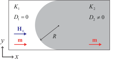
We consider a spin-wave lens with a semi-circular interface between two ferromagnetic films with different anisotropies () and DMIs (), as shown in Fig. 1. The magnetization dynamics is described by the Landau-Lifshitz Gilbert (LLG) equation
| (1) |
where is the unit magnetization vector with the saturated magnetization , Hz/T is the gyromagnetic ratio, is the vacuum permeability, and is the Gilbert damping constant. The effective field comprises the exchange field, the DM field, the anisotropy field, the external magnetic field, and the dipolar field. The DMI considered here has the interfacial form Bogdanov2001
| (2) |
where is the DMI constant. The magnetic anisotropy along the -axis is assumed and the film is uniformly magnetized along the direction (). For simplicity, the dipolar interaction is approximated by the demagnetizing field . For a small fluctuation of around the equilibrium direction , we express the magnetization as with and . Neglecting the damping term (), the spin-wave dispersion relation can be obtained by solving the linearized LLG equation Cortes2013 ; Moon2013
| (3) |
where with the exchange constant , , with the uniaxial anisotropy constant , , and is the wave vector of spin wave. Here represent parameters in the left domain (region 1) and right domain (region 2), respectively, as shown in Fig. 1. In order to facilitate the analysis of spin-wave propagation across the interface, we consider high-frequency spin waves, such that Eq. (3) can be simplified to
| (4) |
Based on Eq. (4), we plot the isofrequency curves of the spin-wave propagation in two regions in space, as shown in Fig. 2(a). In region 1, spin waves with a given frequency form a circle centered at the origin with the radius . In region 2, the isofrequency circle is shifted by along the axis and its radius becomes .
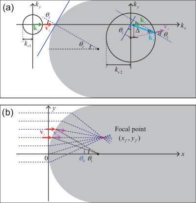
According to the continuity of the wave vector tangent to the interface, we obtain the generalized Snell’s law
| (5) |
where and are the incident and refracted angles with respect to the interface normal, see Fig. 2(a). We assume that spin waves are incident along . So, through an arbitrary incident point on the semicircle, the equation of the refracted ray can be written as
| (6) |
where is the coordinate of an arbitrary point in the refracted beam. From Eqs. (5) and (6), it is obvious to see that the intersection of refracted rays cannot be focused to a single point, which is the so-called spherical aberration caused by the circular shape of the interface. A perfect focusing only happens in the small angle limit, while the ideal shape of the interface to focus all spin waves can be constructed by some sophisticated methods Toedt2016 ; Papp2018 . In our case, the focal point is expected to be present on a refracted spin-wave branch that is parallel with the original incident beam carrying the incident angle
| (7) |
The intersection point of the branch with other refracted rays is then given by
| (8) |
Considering the paraxial (or small-angle) approximation, we obtain the analytical formula of the focal-point coordinate
| (9) |
by taking the limit in Eq. (8). Equation (9) is the main result of the present work, from which one can immediately see that the very presence of DMI leads to an off-axial focusing of spin waves, i.e., if , [see the red dot in Fig. 2(b)]. DMI can also modify the lateral shift .
III Numerical results
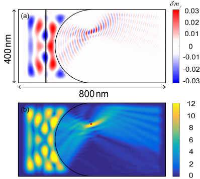
To verify our theoretical results (9), we perform full micromagnetic simulations using MuMax3 Vansteenkiste2014 . We consider a heterogeneous magnetic film with length nm, width nm, and thickness nm. The radius of the semi-circular interface is nm. The magnetic anisotropy constant and the DMI strength are and in the left region (white) and and in the right region (gray), see Fig. 1. Other magnetic parameters are considered as homogeneous: , , and . An example of such a material system is the asymmetric PtCoAl2O3. The difference of magnetic anisotropy can be realized by electrical tuning Ruiz2013 . As an important benchmark for frequency, the spin-wave gaps are GHz in the left domain and GHz in the right domain, respectively, in the absence of external magnetic field. Absorbing boundary conditions have been adopted to avoid the spin-wave reflection by film edges Venkat2018 .
Next, we apply a sinusoidal monochromatic microwave field in a narrow rectangular area [thick black line shown in Fig. 3(a)] to excite the spin waves. We set the amplitude and frequency of the oscillating field as mT and GHz, respectively. Numerical results obtained from micromagnetic simulation are shown in Fig. 3(a). We also calculate the spin-wave intensity based on the formula , as plotted in Fig. 3(b). In Figs. 3(a) and 3(b), one can observe an interference pattern in the left domain, which is caused by the spin-wave reflection by the semi-circular interface. In Fig. 3(b), we clearly find a spin-wave focusing emerging in the right domain. Notably, the focal point obtained from the numerical simulation agrees excellently with the analytical formula Eq. (9) [red point shown in Fig. 3(b)]. In addition, we note that the wavelength of spin waves is significantly shrunk across the interface [see Fig. 3(a)], which is due to the expansion of the radius of the isofrequency circle, as shown in Fig. 2(a). This phenomenon can be considered as an effective method to generate the short-wavelength spin waves, which were conventionally realized by an interface with thickness step Stigloher2016 ; Stigloher2018 or by using the magnetization precession in periodic ferromagnetic nanowires on the top of a neighboring magnetic film Liu2018 .
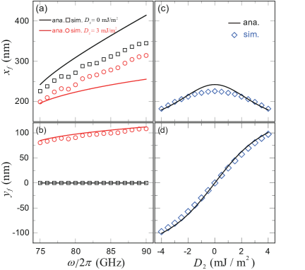
Figures 4(a) and 4(b) show the coordinate of the focal point as a function of the frequency for two DMI constants. When , increases with the spin-wave frequency and is exactly zero. It recovers the expectation that the focal point should be on the lens axis () in non-chiral magnetic media. In the presence of DMI ( ), both and increase with , which demonstrates an off-axial focusing of spin waves. In Figs. 4(c) and 4(d), we plot the dependence of the coordinate of the focal point on the DMI constant for GHz. One can see that decreases and increases with the increasing of , respectively. Furthermore, the sign change of has no effect on , but it reverses the sign of . It can be understood from Eq. (7) that the sign change of can switch the sign of , and thus leads to the sign change of according to Eq. (9). In addition, we note that the magnitude of is always suppressed by DMI. Micromagnetic simulations agree very well with the analytical formula (9) for the lateral shift but not for the horizontal one . There are several reasons that account for this discrepancy. First, the paraxial approximation is adopted in the analytical model, while the incident angles of spin waves in micromagnetic simulation are distributed broadly (). Second, the saturated magnetization is assumed in our theory. However, the spin canting cannot be avoided at the DMI interface (not shown) Wang2019 , which would change the spin-wave propagation and affect the focal point. Lastly, the coordinate of the focal point is obtained numerically by weighted averaging based on the spin-wave intensity, which might lead to sizeable errors.
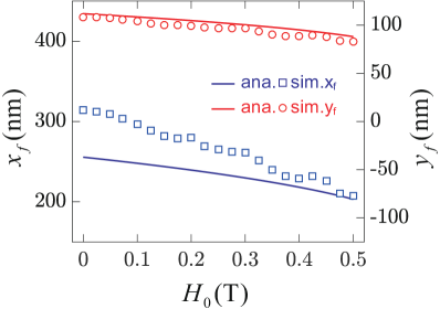
In the above simulations, we have assumed a vanishing external magnetic field, while it could be an effective knob to manipulate the focusing of spin-wave lens. Figure 5 plots the dependence of on the external magnetic field . In the calculations, we set the DMI constant mJ/m2 and the spin-wave frequency GHz. It shows that the horizontal shift can be strongly suppressed by the magnetic field while the lateral shift is less sensitive to it. Numerical results (symbols) are consistent with theoretical formula (curves).
IV Conclusion
In summary, we have theoretically investigated the DMI-induced off-axial focusing of a spin-wave lens. The generalized magnonic Snell’s law at the semi-circular interface and the coordinate of the focal point were analytically derived. We showed that the induced lateral (horizontal) focal-point shift is an odd (even) function of the DMI parameter. While the shifts in both directions increase with the increasing of spin-wave frequency, they are suppressed by the external magnetic field. Full micromagnetic simulations were implemented to compare with theoretical predictions with good agreement. Our findings will help to understand the DMI effect on the spin-wave propagation across curved interface and to design chiral spin-wave optical elements for practical magnonic devices in the future.
V Acknowledgment
This work was supported by the National Natural Science Foundation of China (Grants No. 11604041 and 11704060), the National Key Research Development Program under Contract No. 2016YFA0300801, and the National Thousand-Young-Talent Program of China. Z.W. acknowledges financial support from the China Postdoctoral Science Foundation under Grant No. 2019M653063.
References
- (1) A. A. Serga, A. V. Chumak, and B. Hillebrands, YIG magnonics, J. Phys. D: Appl. Phys. 43, 264002 (2010).
- (2) A. V. Chumak, V. I. Vasyuchka, A. A. Serga, and B. Hillebrands, Magnon spintronics, Nat. Phys. 11, 453 (2015).
- (3) J. N. Toedt, M. Mundkowski, D. Heitmann, S. Mendach, and W. Hansen, Design and construction of a spin-wave lens, Sci. Rep. 6, 33169 (2016).
- (4) A. Papp and G. Csaba, Lens design for computing with anisotropic spin waves, IEEE Magn. Lett. 9, 3706405 (2018).
- (5) O. Dzyapko, I. V. Borisenko, V. E. Demidov, W. Pernice, and S. O. Demokritov, Reconfigurable heat-induced spin wave lenses, Appl. Phys. Lett. 109, 232407 (2016).
- (6) N. J. Whitehead, S. A. R. Horsley, T. G. Philbin, and V. V. Kruglyak, A Luneburg lens for spin waves, Appl. Phys. Lett. 113, 212404 (2018).
- (7) M. Vogel, B. Hillebrands, and G. V. Freymann, Spin-wave optical elements: towards spin-wave fourier optics, arXiv:1906.02301.
- (8) I. Dzyaloshinsky, A thermodynamic theory of “weak” ferromagnetism of antiferromagnetics, J. Phys. Chem. Solids 4, 241 (1958).
- (9) T. Moriya, Anisotropic superexchange interaction and weak ferromagnetism, Phys. Rev. 120, 91 (1960).
- (10) K. Zakeri, Y. Zhang, J. Prokop, T. H. Chuang, N. Sakr, W. X. Tang, and J. Kirschner, Asymmetric Spin-Wave Dispersion on Fe(110): Direct Evidence of the Dzyaloshinskii-Moriya Interaction, Phys. Rev. Lett. 104, 137203 (2010).
- (11) D. Cortés-Ortuño and P. Landeros, Influence of the Dzyaloshinskii-Moriya interaction on the spin-wave spectra of thin films, J. Phys.: Condens. Matter 25, 156001 (2013).
- (12) J.-H. Moon, S.-M. Seo, K.-J. Lee, K.-W. Kim, J. Ryu, H.-W. Lee, R. D. McMichael, and M. D. Stiles, Spin-wave propagation in the presence of interfacial Dzyaloshinskii-Moriya interaction, Phys. Rev. B 88, 184404 (2013).
- (13) F. Garcia-Sanchez, P. Borys, A. Vansteenkiste, J.-V. Kim, and R. L. Stamps, Nonreciprocal spin-wave channeling along textures driven by the Dzyaloshinskii-Moriya interaction, Phys. Rev. B 89, 224408 (2014).
- (14) Y. Onose, T. Ideue, H. Katsura, Y. Shiomi, N. Nagaosa, and Y. Tokura, Observation of the magnon Hall effect, Science 329, 297 (2010).
- (15) T. Ideue, Y. Onose, H. Katsura, Y. Shiomi, S. Ishiwata, N. Nagaosa, and Y. Tokura, Effect of lattice geometry on magnon Hall effect in ferromagnetic insulators, Phys. Rev. B 85, 134411 (2012).
- (16) W. Yu, J. Lan, R. Wu, and J. Xiao, Magnetic Snell’s law and spin-wave fiber with Dzyaloshinskii-Moriya interaction, Phys. Rev. B 94, 140410(R) (2016).
- (17) Z. Wang, B. Zhang, Y. Cao, and P. Yan, Probing the Dzyaloshinskii-Moriya Interaction via the Propagation of Spin Waves in Ferromagnetic Thin Films, Phys. Rev. Applied 10, 054018 (2018).
- (18) J. Mulkers, B. Van Waeyenberge, and M. V. Milošević, Tunable Snell’s law for spin waves in heterochiral magnetic films, Phys. Rev. B 97, 104422 (2018).
- (19) B. Zhang, Z. Wang, Y. Cao, P. Yan, and X. R. Wang, Eavesdropping on spin waves inside the domain-wall nanochannel via three-magnon processes, Phys. Rev. B 97, 094421 (2018).
- (20) Z. Wang, Y. Cao, and P. Yan, Goos-Hänchen effect of spin waves at heterochiral interfaces, Phys. Rev. B 100, 064421 (2019).
- (21) X. Xing and Y. Zhou, Fiber optics for spin waves, NPG Asia Mater. 8, e246 (2016).
- (22) J. Lan, W. Yu, R. Wu, and J. Xiao, Spin-Wave Diode, Phys. Rev. X 5, 041049 (2015).
- (23) J. Orloff, Handbook of Charged Particle Optics, (CRC Press, Boca Raton, FL, 2008).
- (24) D. F. R. Mildner and M. V. Gubarev, Wolter optics for neutron focusing, Nucl. Instrum. Methods Phys. Res. A 634, S7 (2011).
- (25) Y. Li, B. Liang, X. Tao, X.-F. Zhu, X.-Y. Zou, and J.-C. Cheng, Acoustic focusing by coiling up space, Appl. Phys. Lett. 101, 233508 (2012).
- (26) A. N. Bogdanov and U. K. Rossler, Chiral Symmetry Breaking in Magnetic Thin Films and Multilayers, Phys. Rev. Lett. 87, 037203 (2001).
- (27) A. Vansteenkiste, J. Leliaert, M. Dvornik, M. Helsen, F. Garcia-Sanchez, and B. Van Waeyenberge, The design and verification of MuMax3, AIP Adv. 4, 107133 (2014).
- (28) P. Ruiz-Díaz, T. R. Dasa, and V. S. Stepanyuk, Tuning Magnetic Anisotropy in Metallic Multilayers by Surface Charging: An Ab Initio Study, Phys. Rev. Lett. 110, 267203 (2013).
- (29) G. Venkat, H. Fangohr, and A. Prabhakar, Absorbing boundary layers for spin wave micromagnetics, J. Magn. Magn. Mater. 450, 34 (2018).
- (30) J. Stigloher, M. Decker, H. S. Korner, K. Tanabe, T. Moriyama, T. Taniguchi, H. Hata, M. Madami, G. Gubbiotti, K. Kobayashi, T. Ono, and C. H. Back, Snell’s Law for Spin Waves, Phys. Rev. Lett. 117, 037204 (2016).
- (31) J. Stigloher, T. Taniguchi, M. Madami, M. Decker, H. S. Körner, T. Moriyama, G. Gubbiotti, T. Ono, and C. H. Back, Spin-wave wavelength down-conversion at thickness steps, Appl. Phys. Express 11, 053002 (2018).
- (32) C. Liu, J. Chen, T. Liu, F. Heimbach, H. Yu, Y. Xiao, J. Hu, M. Liu, H. Chang, T. Stueckler, S. Tu, Y. Zhang, Y. Zhang, P. Gao, Z. Liao, D. Yu, K. Xia, N. Lei, W. Zhao, and M. Wu, Long-distance propagation of short-wavelength spin waves, Nat. Commun. 9, 738 (2018).