Achievable DoF Regions of Three-User MIMO Broadcast Channel with Delayed CSIT
Abstract
For the two-user multiple-input multiple-output (MIMO) broadcast channel with delayed channel state information at the transmitter (CSIT) and arbitrary antenna configurations, all the degrees-of-freedom (DoF) regions are obtained. However, for the three-user MIMO broadcast channel with delayed CSIT and arbitrary antenna configurations, the DoF region of order-2 messages is still unclear and only a partial achievable DoF region of order-1 messages is obtained, where the order-2 messages and order-1 messages are desired by two receivers and one receiver, respectively. In this paper, for the three-user MIMO broadcast channel with delayed CSIT and arbitrary antenna configurations, we first design transmission schemes for order-2 messages and order-1 messages. Next, we propose to analyze the achievable DoF region of transmission scheme by transformation approach. In particular, we transform the decoding condition of transmission scheme w.r.t. phase duration into the achievable DoF region w.r.t. achievable DoF, through achievable DoF tuple expression connecting phase duration and achievable DoF. As a result, the DoF region of order-2 messages is characterized and an achievable DoF region of order-1 messages is completely expressed. Besides, for order-1 messages, we derive the sufficient condition, under which the proposed achievable DoF region is the DoF region.
Index Terms:
Arbitrary antenna configurations, achievable DoF region, delayed CSIT, three-user MIMO broadcast channel, transformation approach.I Introduction
The multiple-input multiple-output (MIMO) broadcast channel has one transmitter and multiple receivers, all of them are equipped with multiple antennas. For the MIMO broadcast channel, the transmitter sends private messages or common messages to receivers, where the message desired by receivers are denoted by the order- message. As a fundamental metric, the degrees-of-freedom (DoF) denotes the maximal number of interference-free channels that a communication system has in high signal-to-noise ratio (SNR) regime, which is a first-order approximation of channel capacity in high SNR regime. Usually, the DoF is derived based on the match of DoF converse and achievable DoF. The DoF converse is an information-theoretic upper/outer limit, while the achievable DoF is an attainable lower/inner limit. The achievable DoF represents the number of achievable interference-free channels, which is a first-order approximation of data rate in high SNR regime. Moreover, the value of achievable DoF is also embodied in the corresponding transmission schemes for practical use. The DoF region of the MIMO broadcast channel was obtained in [1, 2, 3] when the channel state information at the transmitter (CSIT) is instantaneously obtained. However, when the wireless channel is fast time-varying, the instantaneous CSIT requires a high feedback frequency and a rapid feedback link, which are difficult to satisfy. To resolve that difficulty, utilizing delayed CSIT can alleviate the stringent requirements of feedback frequency and rapidity [4, 5, 6, 7, 8, 9, 10, 11, 12, 13, 14, 15, 16, 17, 18, 19, 20, 21, 22, 23].
I-A Related Work
The research on DoF of MIMO broadcast channel with delayed CSIT can be found in [4, 5, 6, 7, 8, 9]. As a seminal work, in [4], Maddah-Ali and Tse first characterized the DoF region of order- messages for antenna configurations in the -user multiple-input and single-output (MISO), i.e., the transmitter has antennas and each receiver has single antenna. Thereafter, for the two-user MIMO broadcast channel with arbitrary antenna configurations, the DoF region was derived in [5, 6]. For the three-user MIMO broadcast channel with symmetric antenna configurations, i.e., the transmitter has antennas and each receiver has antennas, the DoF characterization was investigated in [7, 8]. In [7], the sum-DoF of order- messages was obtained for and antenna configurations, and an achievable sum-DoF was derived for antenna configurations. In [8], for antenna configurations, we proposed a higher achievable sum-DoF than that in [7] by a holistic higher-order symbol generation. For the three-user MIMO broadcast channel with arbitrary antenna configurations, an achievable DoF region of order-1 messages for antenna configurations was derived in [9]. Furthermore, the study of [9] showed that the achievable DoF region is the DoF region if a sufficient condition holds.
Aside from the DoF of MIMO broadcast channel with delayed CSIT, there are several related research trends [10, 11, 12, 13, 14, 15, 16, 17, 18, 19, 20, 21, 22, 23]. One trend is to investigate the DoF of MIMO broadcast channel with interplay of current, delayed, and no CSIT [10, 11, 12, 13, 14, 15, 16, 17, 18, 19]. In particular, when each receiver has either current, delayed, or no CSIT, i.e., hybrid CSIT, the DoF of MIMO broadcast channel was studied in [10, 11, 12]. For alternating current, delayed, and no CSIT in time for each receiver, i.e., alternating CSIT, the DoF of MIMO broadcast channel was investigated in [13, 14]. Under delayed and current CSIT, i.e., moderately delayed CSIT, a space-time interference alignment scheme for -user MISO broadcast channel was proposed in [15]. Under delayed and imperfect current CSIT, i.e., mixed CSIT, the DoF region of two-user MISO broadcast channel was derived in [16, 17]. Moreover, the DoF region of MIMO interference channel with mixed CSIT was characterized in [18]. A recent study in [19] investigated the sum-DoF of -user MISO broadcast channel with mixed CSIT. On the other hand, the optimization of data rate for the MISO broadcast channel with delayed CSIT was investigated in [20, 21, 22]. For the cached-aided MIMO broadcast channel with delayed CSIT, the memory-DoF tradeoff was studied in [23].
However, the DoF region of three-user MIMO broadcast channel with delayed CSIT is still an open research problem, which is the focus of this paper.
I-B Contributions
In this paper, we investigate the DoF region of three-user MIMO broadcast channel with delayed CSIT and arbitrary antenna configurations. The contributions are summarized as follows:
-
•
DoF Region of Order-2 Messages: For order-2 messages, we characterize the DoF region. For converse, we first present the DoF region with no CSIT, and then derive the DoF outer region with delayed CSIT. For achievability, we first design the transmission scheme, and then obtain the achievable DoF region of transmission scheme by transformation approach.
-
•
Achievable DoF Region of Order-1 Messages: For order-1 messages, since the achievable DoF region was derived for only, we obtain an achievable DoF region for , and a sufficient condition, under which the achievable DoF region is the DoF region. To be specific, for , we design transmission schemes, where the higher-order symbol generation has a sequential manner as that in [7, 9]. For , we design a transmission scheme, which generalizes our holistic design of higher-order symbol generation in [8] to that with arbitrary antenna configurations. Based on proposed transmission schemes, we derive the achievable DoF region and the sufficient condition of optimality by transformation approach.
-
•
Transformation Approach: For the three-user MIMO broadcast channel with delayed CSIT, we propose to analyze the achievable DoF region of transmission scheme by transformation, which overcomes the drawback of achievable DoF region analysis approach in [9]. As for [9], the decoding condition of transmission scheme was used to check whether the DoF outer region is achieved or not. Hence, the achievable DoF region is hard to derive, when the DoF outer region is not attained. To combat the weakness, we propose a transformation approach for achievable DoF region analysis, which transforms the decoding condition of transmission scheme w.r.t. phase duration into the achievable DoF region w.r.t. achievable DoF, through achievable DoF tuple expression connecting phase duration and achievable DoF. Via this transformation approach, we can analyze the achievable DoF region of transmission scheme systematically, even if the DoF outer region is not achieved.
I-C Notations
The scalar, vector, and matrix are denoted by , and H, respectively. and denote transpose and conjugate-transpose, respectively. denotes a tuple with non-negative real numbers. The or is comprised of partial rows of h or H. The convex hull of set is denoted by . The convex hull of a finite set is the set of all convex combinations of its points. The block-diagonal matrix with blocks A and B is denoted by
| (1) |
II System Model
II-A Three-user MIMO Broadcast Channel
The three-user MIMO broadcast channel with arbitrary antenna configurations at the transmitter and three receivers is depicted in Fig. 1, where the transmitter is equipped with antennas and receivers 1, 2 and 3 are equipped with , and antennas, respectively. Without loss of generality, we assume . At the time slot (TS) , the channel state information from the transmitter to the receiver , is denoted by the matrix , whose elements are i.i.d. across space and time, and drawn from a continuous distribution. The received signal in the TS at receiver is expressed as
| (2) |
where the input signal at the transmitter is denoted by and the additive white Gaussian noise (AWGN) at the receiver is denoted by . Given a maximal average transmit power , is subject to an average power constraint, i.e., .
II-B Delayed CSIT
At each TS, each receiver estimates its channel state information matrix and returns it to the transmitter. We assume that the feedback from the receivers to the transmitter is subject to a delay, whose value is not smaller than one TS. Therefore, only delayed channel state information, i.e., , is available at the transmitter. Furthermore, we assume the channel state information at receivers (CSIR) is perfect (without delay).
II-C DoF Region
The order-2 message rate tuple is achievable, if there exists a code such that the probability of decoding error approaches zero when the number of channel uses goes to infinity. The channel capacity region of order-2 message is the region of all achievable rate tuple of order-2 messages satisfying the average power constraint. The DoF region of order-2 messages is defined as follows:
| (3) |
The order-1 message rate tuple is achievable, if there exists a code such that the probability of decoding error approaches zero when the number of channel uses goes to infinity. The channel capacity region is the region of all achievable rate tuple satisfying the average power constraint. The DoF region of order-2 messages is defined as follows:
| (4) |
III DoF Region of Order-2 Messages
In this section, we first present Lemmas 1-3, and then put forward Theorem 1, where Lemmas 1 and 2 are used as achievability proof of Theorem 1, and Lemma 3 is used to prove the converse of Theorem 1.
Lemma 1: If , for the three-user MIMO broadcast channel with delayed CSIT, the DoF region of order-2 messages is given by
| (5) |
Proof:
Please refer to the first part of sub-section B. ∎
Lemma 2: If , for the three-user MIMO broadcast channel with delayed CSIT, the DoF region of order-2 messages is given by
| (6) |
where the third inequality exists if holds.
Proof:
Please refer to the second part of sub-section B. ∎
Lemma 3: For order-2 messages, the DoF region of three-user MIMO broadcast channel with no CSIT is given by
| (7) |
Proof:
Please refer to Appendix A. ∎
Theorem 1: For the three-user MIMO broadcast channel with delayed CSIT, the DoF region of order-2 messages is given by
| (8) |
Proof:
The converse proof is provided in sub-section A and the achievability proof is provided in Lemmas 1 and 2. ∎
III-A Converse Proof
To show the converse, we follow the idea in [4], where similar arguments were used to prove the DoF outer region of order- messages in -user MISO broadcast channel with delayed CSIT. To begin with, a genie creates a physically degraded broadcast channel by providing the output of receiver to receiver . Then, according to [24, 25], the delayed feedback will not change the capacity region of the physically degraded broadcast channel with no feedback, thus the DoF region of order-2 messages with delayed CSIT is equal to the DoF region of order-2 messages with no CSIT. Finally, by Lemma 3, we conclude that
| (9) |
for the physically degraded broadcast channel with delayed CSIT. Permuting all possible receiver indexes, we can obtain the following DoF outer region:
| (10) |
Furthermore, we notice that there are redundant inequalities in (10), i.e.,
| (11a) | |||
| (11b) | |||
| (11c) | |||
which are dominated by the remaining inequalities in (10). Hence, eliminating (11a)-(11c) from (10), we obtain the converse of (8). This completes the proof.
III-B Achievability Proof
III-B1 Proof of Lemma 1
To achieve corner points of (5), we transmit order-2 symbols for receivers 1 and 2, order-2 symbols for receivers 2 and 3, or order-2 symbols for receivers 1 and 3, in each TS. The entire region can be attained through time-sharing of the schemes used in achieving the corner points. This completes the proof.
III-B2 Proof of Lemma 2
The sketch of the proof is given as follows: First, we design a general two-phase transmission scheme with undetermined number of transmit antennas, i.e., , , and , and undetermined phase duration, i.e., , , , and . For the scheme, all order-2 symbols are transmitted in Phase-I and the order-3 symbols that assist the decoding of order-2 symbols are transmitted in Phase-II. Then, we derive the decoding condition of transmission scheme. Finally, we are able to prove the Lemma 2 by transforming the decoding condition and assigning the specific number of transmit antennas.
To begin with, we provide an exemplified transmission scheme when and , as illustrated in Fig. 2. In the TS of Phase-I, two order-2 symbols and desired by receivers 1 and 2 are transmitted with two antennas. The received signals are given by
| (12) |
In the TS of Phase-I, two order-2 symbols and desired by receivers 2 and 3 are transmitted with two antennas. The received signals are given by
| (13) |
In the TS of Phase-I, two order-2 symbols and desired by receivers 1 and 3 are transmitted with two antennas. The received signals are given by
| (14) |
After transmission, in order to decode and , receivers 1 and 2 still need 1 equation. In order to decode and , receivers 2 and 3 still need 1 equation. In order to decode and , receivers 1 and 3 still need 1 equation. Thus, to assist the decoding of order-2 symbols, we design the following order-3 symbols:
| (15) |
In Phase-II, and are transmitted with 1 TS, respectively, so that they can be decoded at receivers 1 and 2 immediately. To supplement the lacking equations, the receiver 1 can obtain by cancellation and by cancellation , the receiver 2 can obtain by cancellation and by , and receiver 3 can obtain by cancellation and by cancellation . Hence, all order-2 symbols can be decoded. The idea of this specific scheme is extended to the general transmission scheme, which is referred to Appendix B.
For the general transmission scheme, in order to decode the order-2 symbol , receiver 1 needs additional equations, and receiver 2 needs additional equations. In order to decode the order-2 symbol , receiver 2 needs additional equations, receiver 3 needs additional . In order to decode the order-2 symbol , receiver 1 needs additional equations, and receiver 3 needs additional equations. The Phase-II spans TSs. Based on the CSIT of Phase-I, the order-3 symbols are generated at the transmitter by (66) in Appendix B to assist the decoding of desired order-2 symbols at receivers 1, 2 and 3. Since the phase duration is undetermined, we need to figure out the feasible phase duration, under which the transmitted order-2 symbols are decodable. In the Phase-II, we provide equations for receiver 1, equations for receiver 2, and equations for receiver 3, so that the transmitted order-2 symbols in the Phase-I can be decoded at receivers 1, 2, and 3. The feasible phase duration, , and should satisfy the following inequalities:
| (16a) | |||
| (16b) | |||
| (16c) | |||
where (16a) represents the number of lacking equations at receiver 1 should be not more than the number of received equations at receiver 1, (16b) represents the number of lacking equations at receiver 2 should be not more than the number of received equations at receiver 2, and (16c) represents the number of lacking equations at receiver 3 should be not more than the number of received equations at receiver 3. Consequently, we refer the inequalities (16a)-(16c) to as the decoding condition of this transmission scheme.
Once the decoding condition is obtained, we are able to analyze the achievable DoF region of transmission scheme by transformation approach, whose procedure is detailed as follows: Adding , , and at both sides of (16a)-(16c), respectively, we have
| (17a) | |||
| (17b) | |||
| (17c) | |||
where . Then, dividing both sides of (17a)-(17c) by , and , respectively, we have
| (18a) | |||
| (18b) | |||
| (18c) | |||
The achievable DoF tuple is expressed as
| (19) |
where implies . Next, we assign specific value to , and so that (6) can be achieved. For Case, we can set and . Due to and , (16c) always satisfies, which implies (18c) does not exist in this case. For Case, we can set and . In all cases, substituting (19) into (18a)-(18b) or (18a)-(18c), we have (6). This completes the proof.
IV Achievable DoF Region of Order-1 Messages
In this section, we present the achievable DoF region of order-1 messages by dividing all the antenna configurations into four specific cases, and show their achievable DoF region via Theorems 2-4, respectively. Moreover, in Corollary 1, we provide the sufficient condition, under which the proposed achievable DoF region is the DoF region. Before we move on, we present the following antenna configuration condition, which is repeatedly used in Theorems 2 and 3, Corollaries 1 and 2:
As a remark, it can be verified that leads to the invalidation of the above condition.
IV-A Case 1:
In this case, an achievable DoF region of order-1 messages was characterized in Theorem 2 of [9], which is the DoF region if an antenna configuration condition holds. The sketch of the proof of Theorem 2 in [9] is illustrated as follows: Firstly, a transmission scheme was designed with undetermined phase duration, where the decoding condition w.r.t. phase duration was derived. Secondly, the achievable DoF tuple was substituted into the strictly positive corner point of the DoF outer region, which was subsequently simplified into the expression w.r.t. phase duration. Finally, if the simplified expression is equal to the decoding condition, then the achievable DoF region is the same as the DoF outer region. Otherwise, the achievable DoF region of transmission scheme is hard to derive, due to the mismatch of DoF outer region.
IV-B Case 2:
Theorem 2: For the three-user MIMO broadcast channel with delayed CSIT, if , the achievable DoF region of order-1 messages is given by
| (20) |
where and, if the condition holds, the corner point is the intersection of the following planes:
| (21a) | |||
| (21b) | |||
| (21c) | |||
Otherwise, the corner point is the intersection of following planes:
| (22) |
Proof:
The achievable DoF region in Theorem 2 can be achieved by the time-sharing (convex combination) of , , and corner point . The regions , and are equal to setting one coordinate of DoF outer region in [5] to zero. Since , and belong to regions of two-user MIMO broadcast channel with delayed CSIT, all of them can be achieved by the scheme in [5]. We shall show that the corner point is achieved by the following three-phase transmission scheme:
The sketch of the proposed transmission scheme is given as follows: In Phase-I, all the order-1 symbols are transmitted with the assigned number of transmit antennas. After the Phase-I transmission, the receivers cannot decode the desired symbols immediately, due to the lack of received equations and interference. To provide the lacking equations and remove the interference, order-2 symbols are generated at the transmitter with the CSIT of Phase-I. The transmission of Phase-II and Phase-III are through the proposed two-phase transmission scheme in Appendix B.
To begin with, we provide an exemplified transmission scheme when and . In the TS of Phase-I, two order-1 symbols and desired by receiver 1 and two order-1 symbols and desired by receiver 2 are transmitted with two antennas. The designed transmit signal is given by
| (23) |
The received signals are given by
| (24) |
In the TS of Phase-I, two order-1 symbols and desired by receiver 2 and two order-1 symbols and desired by receiver 3 are transmitted with two antennas. The designed transmit signal is given by
| (25) |
The received signals are given by
| (26) |
In the TS of Phase-I, two order-1 symbols and desired by receiver 1 and two order-1 symbols and desired by 3 are transmitted with two antennas. The designed transmit signal is given by
| (27) |
The received signals are given by
| (28) |
Due to the interference in received signals and lack of equations, each receiver cannot decode its desired symbols. To assist the decoding, as depicted in Fig. 3, the order-2 symbols are designed as follows: If we provide to receivers 1 and 2, then receiver 1 can acquire 1 equation by cancellation , receiver 2 can 1 equation directly. Hence, is an order-2 symbol desired by receivers 1 and 2 and is denoted by . Likewise, , , , , and . These order-2 symbols are transmitted via the exemplified transmission scheme given in the proof of Lemma 2. The generalized Phase-I transmission and order-2 symbol generation in the above example are provided in Appendix C. In the following, we elaborate on the general transmission scheme.
The Phase-I spans TSs, where order-1 symbols are transmitted via the strategy in Appendix C with and . After the transmission of order-1 symbols, receivers 1, 2, and 3 cannot decode the desired symbols, due to the lack of equations and the interference incurred by coded transmission.
The Phase-II spans TSs. Utilizing the CSIT of Phase-I, we generate and transmit the order-2 symbol , and via the strategy in Appendix C to assist receivers 1, 2 and 3 to decode their desired order-1 symbols. Then, we transmit these order-2 symbols via the strategy in Appendix B, where . Therefore, the phase duration for order-2 symbol transmission should satisfy the following equivalence relationship:
| (29a) | |||
| (29b) | |||
| (29c) | |||
The Phase-III spans TSs. Utilizing the CSIT of Phase-II, we generate the order-3 symbol via the strategy in Appendix B. In Phase-III, order-3 symbols are transmitted with antennas. The phase duration of Phase-III should be assigned to the value that all receivers can acquire their lacking equations with the same amount of TSs. Thus, according to (16a)-(16c), we have
| (30a) | |||
| (30b) | |||
| (30c) | |||
The relationship (29a)-(29c) and linear system (30a)-(30c) are the decoding condition. The linear system (30a)-(30c) can be solved by the Matlab symbolic calculation, where if the condition holds, a non-negative solution of the linear system (30a)-(30c) can be given by
| (31a) | |||
| (31b) | |||
| (31c) | |||
| (31d) | |||
where non-negativity is ensured by and implied by the satisfaction of the condition , and the other non-negative solutions are the scaling version of (31a)-(31d).
Once the decoding condition, i.e., the relationship (29a)-(29c) and linear system (30a)-(30c), is obtained, we are able to derive the achievability of corner point by transformation approach, whose procedure is detailed as follows: Adding , and at the both sides of (30a)-(30c), respectively, we have
| (32a) | |||
| (32b) | |||
| (32c) | |||
where . Replacing , and with , and using (29a)-(29c), and then dividing both sides with , , and , respectively, we have
| (33a) | |||
| (33b) | |||
| (33c) | |||
Since the achievable DoF tuple is expressed as
| (34) |
we have
| (35) |
After re-writing (33a)-(33c) through (34) and (35), the corner point can be expressed as the intersection of (21a)-(21c).
If the condition does not hold, we cannot obtain a non-negative solution of the linear system (30a)-(30c), due to . Therefore, we shift to solve
| (36a) | |||
| (36b) | |||
| (36c) | |||
for achieving a corner point. A non-negative solution can be given by . Based on (29a)-(29c), the Phase-I duration can be derived accordingly. Due to the relationship revealed by (29a) and (35), the corner point can be equivalently expressed as the intersection of (21a), (21b) and . This completes the proof. ∎
Corollary 1: If the condition holds with equality, the achievable DoF region in Theorem 2 is the DoF region.
Proof:
According to [5], a DoF outer region is given by
| (37) |
Due to , we only need to show the achievability of strictly positive corner point. As shown in the proof of Theorem 2, if the condition holds with equality, we have . This implies , due to (35). Therefore, in this case, the strictly positive corner point of the DoF outer region is the same as . ∎
Remark: Corollary 1 shows the sufficient condition, under which the achievable DoF region in Theorem 2 is the DoF region. Moreover, in Table I, we provide some antenna configurations that satisfy Corollary 1.
| 3 | 6 | 7 | 9 | 12 | 13 | 14 | 15 | 18 | 21 | 21 | 21 | 24 | 26 | |
| 3 | 6 | 14 | 9 | 12 | 39 | 28 | 15 | 18 | 21 | 42 | 84 | 24 | 78 | |
| 4 | 8 | 15 | 12 | 16 | 40 | 30 | 20 | 24 | 28 | 45 | 85 | 32 | 80 | |
| 7 | 13,14 | 22 | 19-21 | 25-28 | 53 | 43,44 | 31-35 | 37-42 | 43-49 | 64-66 | 106 | 49-56 | 95-106 |
IV-C Case 3:
Theorem 3: For the three-user MIMO broadcast channel with delayed CSIT, if , the achievable DoF region of order-1 messages is given by
| (38) |
where , and, if the condition holds, the corner point is the intersection of following planes:
| (39a) | |||
| (39b) | |||
| (39c) | |||
Otherwise, the corner point is the intersection of following planes:
| (40) |
Proof:
Similar to Theorem 2, we only need to show that the corner point is achieved by the following three-phase transmission scheme, where the number of used transmit antennas, the number of order-2 and order-3 symbols, and the phase duration are different from the scheme in Theorem 2.
The Phase-I spans TSs, where order-1 symbols are transmitted via the strategy in Appendix C with , , and . After the transmission of order-1 symbols, receivers 1, 2, and 3 cannot decode the desired symbols, due to the lack of equations and the interference incurred by coded transmission.
The Phase-II spans TSs. Utilizing the CSIT of Phase-I, we generate the order-2 symbol and via the strategy in Appendix C to assist receivers 1, 2, and 3 to decode their desired order-1 symbols. Then, we transmit these order-2 symbols via the strategy in Appendix B, where . Therefore, the phase duration for order-2 symbol transmission should satisfy the following equivalence relationship:
| (41a) | |||
| (41b) | |||
| (41c) | |||
The Phase-III spans TSs. Utilizing the CSIT of Phase-II, we generate the order-3 symbol via the strategy in Appendix B. In Phase-III, all the order-3 symbols are transmitted with antennas. The phase duration of Phase-III should be assigned to the value that all receivers can acquire their lacking equations with the same amount of TSs. Thus, according to (16a)-(16c), we have
| (42a) | |||
| (42b) | |||
| (42c) | |||
The relationship (41a)-(41c) and linear system (42a)-(42c) are the decoding condition. The linear system (42a)-(42c) can be solved by the Matlab symbolic calculation, where if the condition holds, a non-negative solution of the linear system (42a)-(42c) can be given by
| (43a) | |||
| (43b) | |||
| (43c) | |||
| (43d) | |||
where non-negativity is ensured by and implied by the satisfaction of the condition , and the other non-negative solutions are scaling version of (43a)-(43d).
Once the decoding condition, i.e., the relationship (41a)-(41c) and linear system (42a)-(42c), is obtained, we are able to derive the achievability of corner point by transformation approach, whose procedure is detailed as follows: Adding , and at the both sides of (42a)-(42c) respectively, we have
| (44a) | |||
| (44b) | |||
| (44c) | |||
where . Replacing , and with , and using (41a)-(41c), and then dividing both sides with , , and , respectively, we have
| (45a) | |||
| (45b) | |||
| (45c) | |||
Since the achievable DoF tuple is expressed as
| (46) |
we have
| (47a) | |||
| (47b) | |||
After re-writing (45a)-(45c) through (46), (47a) and (47b), the corner point can be expressed as an intersection of (39a)-(39c).
If the condition does not hold, we cannot obtain a non-negative solution of the linear system (42a)-(42c), due to . Therefore, we shift to solve
| (48a) | |||
| (48b) | |||
| (48c) | |||
for achieving a corner point. A non-negative solution can be given by , , . Based on (41a)-(41c), the Phase-I duration can be derived accordingly. Due to the relationship revealed by (47a) and (47b), the corner point can be equivalently expressed as the intersection of (39a), (39b) and . This completes the proof. ∎
Corollary 2: If the condition holds with equality and gradually reduces to , the achievable DoF region in Theorem 3 approaches the DoF region.
Proof:
According to [5], a DoF outer region is given by
| (49) |
Due to , we only need to examine the strictly positive corner point. As shown in the proof of Theorem 3, if the condition holds with equality, we have . This implies , due to (47a). In addition, when gradually reduces to , is asymptotically dominated by in (49), meanwhile in (39a)-(39b) goes to zero. Therefore, in this case, the corner point approaches the strictly positive corner point of the DoF outer region. ∎
IV-D Case 4:
Theorem 4: For the three-user MIMO broadcast channel with delayed CSIT, if , the achievable DoF region of order-1 messages is given by
| (50) |
where and the corner point is the intersection of following planes:
| (51a) | |||
| (51b) | |||
| (51c) | |||
Meanwhile, the corner point should satisfy
| (52a) | |||
| (52b) | |||
| (52c) | |||
Remark: If antenna configurations are symmetric (), the corner point is given by . In fact, Theorem 4 generalizes the result in our conference paper [8] for symmetric antenna configurations to the setting of arbitrary antenna configurations.
Proof:
Similar to Theorem 2, we only need to show that the corner point is achieved by the following three-phase transmission scheme:
The sketch of the proposed transmission scheme is given as follows: In Phase-I, all the order-1 symbols are transmitted with the assigned number of transmit antennas. After the Phase-I transmission, the receivers cannot decode the desired symbols immediately, due to the lack of received equations. To provide the lacking equations, order-2 symbols and order-3 symbols are generated at the transmitter with the CSIT of Phase-I. The transmission of the Phase-II and Phase-III are through the proposed two-phase transmission scheme in Section-III. In the following, we elaborate on the proposed transmission scheme as follows:
The Phase-I spans TSs, where order-1 symbols are transmitted via the strategy in Appendix C with . After the transmission of order-1 symbols, receivers 1, 2, and 3 cannot decode the desired symbols, due to the lack of equations and the interference incurred by coded transmission.
The Phase-II spans TSs. Utilizing the CSIT of Phase-I, we generate the order-2 symbol and via the strategy in Appendix C for assisting receivers 1, 2, and 3 to decode the desired order-1 symbols. Nevertheless, this is not enough. We further generate additional order-2 symbols and order-3 symbols for completely decoding order-1 symbols. The additional order-2 symbols are given by
| (53a) | |||
| (53b) | |||
| (53c) | |||
The additional order-3 symbols are given by
| (54) |
Then, we transmit these order-2 symbols via the strategy in Appendix B, where . Therefore, the phase duration for order-2 symbol transmission should satisfy the following equivalence relationship:
| (55a) | |||
| (55b) | |||
| (55c) | |||
The Phase-III spans TSs. Utilizing the CSIT of Phase-II, we generate the order-3 symbol via the strategy in Appendix B. In Phase-III, all the order-3 symbols are transmitted with antennas. The phase duration of Phase-III should be assigned to the value that all receivers can acquire their lacking equations with the same amount of TSs. Thus, considering (16a)-(16c) and (54), we have
| (56a) | |||
| (56b) | |||
| (56c) | |||
The relationship (55a)-(55c) and linear system (56a)-(56c) are decoding condition.
Once the decoding condition is obtained, we are able to derive the achievability of corner point by transformation approach, whose procedure is detailed as follows: Adding , and at both sides of (56a)-(56c), respectively, we have
| (57a) | |||
| (57b) | |||
| (57c) | |||
where . Replacing , and with , and using (55a)-(55c), and then dividing both sides of (57a)-(57c) with , , and , respectively, we have
| (58a) | |||
| (58b) | |||
| (58c) | |||
Since the achievable DoF tuple is expressed as
| (59) |
we have
| (60a) | |||
| (60b) | |||
| (60c) | |||
After re-writing (58a)-(45c) through (59), (60a)-(60c), the corner point can be expressed as an intersection of (51a)-(51c). To ensure non-negative solution of the linear system (56a)-(56c), due to (55a)-(55c) and (60a)-(60c), we require (52a)-(52c) hold. This completes the proof. ∎
IV-E Compared with DoF Outer Region
In this section, for order-1 messages, we compare the proposed achievable DoF region with the DoF outer region in [5]. Numerically, we calculate the achievable sum-DoF from the proposed achievable DoF region and the sum-DoF upper bound from the DoF outer region in [5]. The sum-DoF upper bound is defined as maximizing over the DoF outer region and the achievable sum-DoF is defined as maximizing over the achievable DoF region. It can be verified that the optimal solution is the strictly positive corner point.
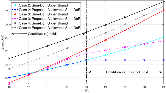
In Case 2, Fig. 4 depicts that, if the condition holds, the proposed achievable sum-DoF is extremely close to the sum-DoF upper bound, which implies the satisfactory performance of proposed scheme. If the condition is not satisfied, the DoF gap between the achievable sum-DoF and sum-DoF upper bound is increasingly larger. This is because, in Case 2, the sum-DoF upper bound is related to , but the proposed achievable sum-DoF is not affected by . In Case 3, Fig. 4 shows that, if the condition holds, the proposed achievable sum-DoF is close to the sum-DoF upper bound, however, the difference is greater than that of Case 2, and the gap will also grow as increases. In Case 4, which is irrelevant to the condition , Fig. 4 depicts that the gap between sum-DoF upper bound and achievable sum-DoF reduces as approaches . To sum up, Fig. 4 shows that the condition is critical because whether it holds or not significantly affects the performance of the proposed design. We can infer from Fig. 4 that, in Case 4, the larger is the difference between and , the greater is the performance gap.
V Comparison of DoF Regions with Perfect, Delayed, and no CSIT
In this section, the usefulness of delayed CSIT is verified by comparison of the DoF regions with perfect, delayed, and no CSIT. For order-2 and order-1 messages, we shall show that the DoF region with delayed CSIT are larger than the DoF region with no CSIT if , which contains the majority of antenna configurations. While, according to [1, 2, 3, 9] and results of this paper, the DoF region with delayed CSIT are not larger than the one with perfect CSIT.

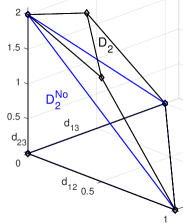
For order-2 messages, the DoF region with no CSIT is derived by the corollary of Theorem 1 in [26], which is denoted by . Examined inequalities of and 111 is given by Theorem 1 in this paper., if , it can be verified that . Otherwise, we have . In other words, for order-2 messages, the delayed CSIT is useful when . In Fig. 5, we provide an example for . In Fig. 6, we provide an example for .
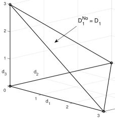
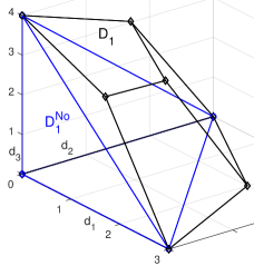
For order-1 messages, according to [26], the DoF region with no CSIT is given by . We compare the results in [9] and this paper with , by examining inequalities of and . When , it can be verified that 222 denotes the DoF region of three-user MIMO broadcast channel with delayed CSIT and order-1 messages.. Otherwise, we have . In other words, for order-1 messages, the delayed CSIT is useful when . In Fig. 7, we provide an example for . In Fig. 8, we provide an example for .
VI Conclusions
For the three-user MIMO broadcast channel with delayed CSIT and arbitrary antenna configurations, we have characterized the DoF region of order-2 messages for arbitrary antenna configurations. We have also obtained an achievable DoF of order-1 messages for antenna configurations, which complements the insufficiency of the existing results. The results of this paper rely on the design of transmission scheme and the transformation approach. In particular, the transformation approach can systematically analyze the achievable DoF region of transmission scheme, whereas traditional methods cannot. Since the decoding condition of transmission scheme with delayed CSIT exists in general, the transformation approach has potential applications in the -user MIMO broadcast channel and the other multi-user channels. In the future, two applications of our transformation approach will be elaborated, which are given as follows: 1) Appending the fresh order-3 message transmission in the last phase of our transmission schemes and applying the transformation approach, we can obtain the achievable DoF region of three-user MIMO broadcast channel with delayed CSIT, private and common messages; and 2) Generalizing our achievability and converse of order-2 messages to that of order- messages, we can derive the DoF region of -user MIMO broadcast channel with delayed CSIT and order- messages.
Appendix A Proof of Lemma 3
The idea of proving this Lemma borrows from that of proving the Theorem 1 in [26]. Similar to [26], a genie enhances the broadcast channel by providing and to receiver 2, and to receiver 3, where the order-2 message desired by receivers 1 and 2 is denoted by , the order-2 message desired by receivers 2 and 3 is denoted by , and the order-2 message desired by receivers 1 and 3 is denoted by . According to Fano’s inequality, the data rates of messages , and are bounded by
| (61a) | |||
| (61b) | |||
where the collection across channel uses of output signals at receiver , and CSI matrices are denoted by , and , respectively; and . Based on (61a) and (61b), we have
| (62) |
where (a) is from applying (61a)-(61b); (b) is from ; and (c) is from by Lemma and (18) in [26]. We can obtain a DoF outer region, having the same expression as (7), by dividing both sides of (62) by and taking the limit of . This DoF outer region can be achieved by the same way in the proof of Lemma 1. This completes the proof.
Appendix B General Transmission Scheme for Order-2 Symbols
In the first step of Phase-I, the order-2 symbols desired by receivers 1 and 2 are transmitted with TSs and transmit antennas 333The vector of order-2 symbols desired by receivers 1 and 2 is denoted by . The vector of order-2 symbols desired by receivers 2 and 3 is denoted by . The vector of order-2 symbols desired by receivers 1 and 3 is denoted by . The vector of order-3 symbols desired by receivers 1, 2, and 3 is denoted by .. The received signals are given by
| (63) |
In the second step of Phase-I, the order-2 symbols desired by receivers 2 and 3 are transmitted with TSs and transmit antennas. The received signals are given by
| (64) |
In the final step of Phase-I, the order-2 symbols desired by receivers 1 and 3 are transmitted with TSs and transmit antennas. The received signals are given by
| (65) |
If the order-2 symbols cannot be decoded instantaneously, we design order-3 symbols to facilitate the decoding of transmitted order-2 symbols. Based on the Phase-I CSIT, the design of such order-3 symbols can be given by
| (66) |
where , and are truncated vectors from , and , respectively. After decoding , receiver 1 can acquire by cancellation and by cancellation . After decoding , receiver 2 can acquire by cancellation and by cancellation . After decoding , receiver 3 can acquire by cancellation and by cancellation . Therefore, are used for the decoding of order-2 symbols at all receivers, which are order-3 symbols. In Phase-II, order-3 symbols are transmitted with TSs and antennas. To ensure the instantaneous decoding of order-3 symbols, we set if , and otherwise.
Appendix C Coded Transmission of Order-1 Symbols
At the first step, is transmitted using TSs and transmit antennas, which is a sum of receivers 1 and 2 desired symbols 444The vector of order-1 symbols desired by receivers 1, 2, and 3 are denoted by , , , respectively.. The received signals are given by
| (67) |
At the second step, is transmitted using TSs and transmit antennas, which is a sum of receivers 2 and 3 desired symbols. The received signals are given by
| (68) |
At the final step, is transmitted using TSs and transmit antennas, which is a sum of receivers 1 and 3 desired symbols. The received signals are given by
| (69) |
To provide equations in order to decode the transmitted order-1 symbols, based on the CSIT from the to the TS, we design the following order-2 symbols:
-
•
This design aims to provide equations about to receiver 1 and equations about to receiver 2. Given to receivers 1 and 2, then receiver 1 will acquire equations, and receiver 2 will acquire equations as well by , due to . If we provide to receivers 1 and 2, then receiver 1 will obtain new equations by , and receiver 2 will obtain new equations as well. The generated order-2 symbols are
(70) -
•
This design aims to provide equations about to receiver 2 and equations about to receiver 3. Given to receivers 2 and 3, then receiver 2 will acquire equations, and receiver 3 will acquire equations as well by , due to . If we provide to receivers 2 and 3, then receiver 2 will obtain new equations by , and receiver 3 will obtain new equations as well. The generated order-2 symbols are
(71) -
•
This design aims to provide equations about to receiver 1 and equations about to receiver 3. Given to receivers 1 and 3, then receiver 1 will acquire equations, and receiver 3 will acquire equations as well by , due to . If we provide to receivers 1 and 3, then receiver 1 will obtain new equations by , and receiver 3 will obtain new equations as well. The generated order-2 symbols are
(72)
References
- [1] H. Weingarten, Y. Steinberg, and S. Shamai, “The capacity region of the Gaussian multiple-input multiple-output broadcast channel,” IEEE Trans. Inf. Theory, vol. 52, no. 9, pp. 3936–3964, Sept. 2006.
- [2] Q. H. Spencer, A. L. Swindlehurst, and M. Haardt, “Zero-forcing methods for downlink spatial multiplexing in multiuser MIMO channels,” IEEE Trans. Signal Processing, vol. 52, no. 2, pp. 461–471, Feb. 2004.
- [3] B. Asadi, L. Ong, and S. J. Johnson, “The DoF region of the three-receiver gaussian MIMO broadcast channel with receiver message side information,” IEEE Trans. Commun., vol. 65, no. 5, pp. 2000–2010, May 2017.
- [4] M. A. Maddah-Ali and D. Tse, “Completely stale transmitter channel state information is still very useful,” IEEE Trans. Inf. Theory, vol. 58, no. 7, pp. 4418–4431, July 2012.
- [5] C. S. Vaze and M. K. Varanasi, “The degrees of freedom region of the two-user MIMO broadcast channel with delayed CSIT,” in Proc. IEEE Int. Symp. Inf. Theory (ISIT), St. Petersburg, Russia, 2011, pp. 199–203.
- [6] ——, “The degrees of freedom regions of two-user and certain three-user MIMO broadcast channels with delayed CSIT,” arXiv preprint arXiv:1101.0306, 2010.
- [7] M. J. Abdoli, A. Ghasemi, and A. K. Khandani, “On the degrees of freedom of three-user MIMO broadcast channel with delayed CSIT,” in Proc. IEEE Int. Symp. Inf. Theory (ISIT), St. Petersburg, Russia, 2011, pp. 209–213.
- [8] T. Zhang, X. W. Wu, Y. F. Xu, Y. Ge, and P. C. Ching, “Three-user MIMO broadcast channel with delayed CSIT: A higher achievable DoF,” in Proc. IEEE Int. Conf. Acoust., Speech, Signal Process. (ICASSP), 2018, pp. 3709–3713.
- [9] M. J. Abdoli, “Feedback and cooperation in wireless networks,” Ph.D. dissertation, University of Waterloo, 2012.
- [10] S. Amuru, R. Tandon, and S. Shamai, “On the degrees-of-freedom of the 3-user MISO broadcast channel with hybrid CSIT,” in Proc. IEEE Int. Symp. Inf. Theory (ISIT), Honolulu, USA, June 2014, pp. 2137–2141.
- [11] S. Lashgari, R. Tandon, and S. Avestimehr, “MISO broadcast channel with hybrid CSIT: Beyond two users,” IEEE Trans. Inf. Theory, vol. 62, no. 12, pp. 7056–7077, Dec. 2016.
- [12] Y. Wang and M. K. Varanasi, “Degrees of freedom of the two-user MIMO broadcast channel with private and common messages under hybrid CSIT models,” IEEE Trans. Inf. Theory, vol. 63, no. 9, pp. 6004–6019, Sept. 2017.
- [13] R. Tandon, S. A. Jafar, S. Shamai, and H. V. Poor, “On the synergistic benefits of alternating CSIT for the MISO broadcast channel,” IEEE Trans. Inf. Theory, vol. 59, no. 7, pp. 4106–4128, July 2013.
- [14] B. Rassouli, C. Hao, and B. Clerckx, “DoF analysis of the MIMO broadcast channel with alternating/hybrid CSIT,” IEEE Trans. Inf. Theory, vol. 62, no. 3, pp. 1312–1325, Mar. 2016.
- [15] N. Lee and R. W. Heath, “Space-time interference alignment and degree-of-freedom regions for the MISO broadcast channel with periodic CSI feedback,” IEEE Trans. Inf. Theory, vol. 60, no. 1, pp. 515–528, Jan. 2014.
- [16] S. Yang, M. Kobayashi, D. Gesbert, and X. Yi, “Degrees of freedom of time correlated MISO broadcast channel with delayed CSIT,” IEEE Trans. Inf. Theory, vol. 59, no. 1, pp. 315–328, Jan. 2013.
- [17] T. Gou and S. A. Jafar, “Optimal use of current and outdated channel state information: Degrees of freedom of the MISO BC with mixed CSIT,” IEEE Commun. Lett., vol. 16, no. 7, pp. 1084–1087, July 2012.
- [18] X. Yi, S. Yang, D. Gesbert, and M. Kobayashi, “The degrees of freedom region of temporally correlated MIMO networks with delayed CSIT,” IEEE Trans. Inf. Theory, vol. 60, no. 1, pp. 494–514, Jan. 2014.
- [19] P. de Kerret, D. Gesbert, J. Zhang, and P. Elia, “Optimal DoF of the K-user broadcast channel with delayed and imperfect current CSIT,” IEEE Trans. Inf. Theory, pp. 1–1, 2020.
- [20] M. Dai and B. Clerckx, “Transmit beamforming for MISO broadcast channels with statistical and delayed CSIT,” IEEE Trans. Commun., vol. 63, no. 4, pp. 1202–1215, Apirl 2015.
- [21] X. Yi and D. Gesbert, “Precoding methods for the MISO broadcast channel with delayed CSIT,” IEEE Trans. Wireless Commun., vol. 12, no. 5, pp. 1–11, May 2013.
- [22] Y. Luo and T. Ratnarajah, “Robust stochastic optimization for MISO broadcast channel with delayed CSIT and limited transmitting antennas,” IEEE Trans. Veh. Technol., vol. 64, no. 8, pp. 3547–3559, Aug. 2015.
- [23] J. Zhang and P. Elia, “Fundamental limits of cache-aided wireless BC: Interplay of coded-caching and CSIT feedback,” IEEE Trans. Inf. Theory, vol. 63, no. 5, pp. 3142–3160, May 2017.
- [24] A. E. Gamal, “The feedback capacity of degraded broadcast channels (corresp.),” IEEE Trans. Inf. Theory, vol. 24, no. 3, pp. 379–381, May 1978.
- [25] ——, “The capacity of the physically degraded Gaussian broadcast channel with feedback (corresp.),” IEEE Trans. Inf. Theory, vol. 27, no. 4, pp. 508–511, July 1981.
- [26] B. Rassouli, C. Hao, and B. Clerckx, “A new proof for the DoF region of the MIMO networks with no CSIT,” IEEE Commun. Lett., vol. 19, no. 5, pp. 763–766, May 2015.