Time-resolved diffraction with an optimized short pulse laser plasma X-ray source
Abstract
We present a set-up for time-resolved X-ray diffraction based on a short pulse, laser-driven plasma X-ray source. The employed modular design provides high flexibility to adapt the set-up to the specific requirements (e.g. X-ray optics, sample environment) of particular applications. The configuration discussed here has been optimized towards high angular/momentum resolution and uses Kα-radiation (4.51 keV) from a Ti wire-target in combination with a toroidally bent crystal for collection, monochromatization and focusing of the emitted radiation. Ti-Kα1 photons per pulse with relative bandwidth are delivered to the sample at 10 Hz repetition rate. This allows for high dynamic range () measurements of transient changes of the rocking curves of materials as for example induced by laser-triggered strain waves.
pacs:
78.47.J-, 61.05.C, 63.30.ddI Introduction
By combining atomic scale spatial and temporal resolution ultrafast time-resolved diffraction using short X-ray or electron pulses provides direct access to the atomic motions in materials on their natural time-scale, i.e. femtoseconds to picoseconds. This relatively new field of structural dynamics has seen tremendous progress in recent years mainly driven by the development of new sources (e.g. refs. 1; 2; 3; 4 and references therein). In the case of X-rays the current standard is set by X-ray free electron lasers, which exhibit extreme brightness, ultrashort pulse duration (currently down to the few fs level) and spatial coherence offering spectacular new opportunitiesBostedt et al. (2016). While more and more of these large-scale facilities are getting operational and available to users, access is highly competetive and still very limited. Therefore, as an alternative lab-scale approaches are still being pursued and developed. Among those the hard X-ray emission of short-pulse laser-produced plasmas has found wide-spread use for radiography/imaging (e.g. refs. 6; 7; 8), time-resolved X-ray absorption (e.g. refs. 9; 10; 11; 12; 13) and, in particular, for ultrafast diffraction (e.g. refs. 14; 15; 16; 17; 18; 19; 20; 21; 22; 23; 24). In fact, the first time-resolved X-ray diffraction experiment with sub-picosecond resolution has been performed at such a sourceRischel et al. (1997).
By focusing a femtosecond laser pulse at intensities in excess of Wcm-2 onto the surface of a solid target high temperature plasmas with near-solid-density can be generated Gibbon (2005) which represent an efficient source of hard X-rays Kühlke, Herpers, and von der Linde (1987); Murnane et al. (1991). The emitted radiation contains continuum and characteristic line emission from the thin surface plasma layer as well as the "cold" solid behind. Due to collisionless interactionsBrunel (1987); Gibbon and Bell (1992); Teubner et al. (1993, 1996); Teubner, Theobald, and Wülker (1996); Reich et al. (2000); Ziener et al. (2002); Reich et al. (2003); Weisshaupt et al. (2015) (resonance absorption and/or vacuum heating) between the created plasma and the laser pulse, a fraction of the plasma electrons is accelerated to kinetic energies of several tens of keV, much higher than the thermal energy of the rest of the plasma electrons (several hundreds of eV)Rousse et al. (1994). These "hot" electrons generate Bremsstrahlung and characteristic line emission very similar to a conventional X-ray tube by penetrating into the cold solid underneath the plasma layer. Since these high energy, "hot" electrons are a result of the direct laser-plasma interaction, the X-ray pulse duration can be comparable to the driving laser pulse duration Reich et al. (2000); Zamponi et al. (2010).
The efficiency of X-ray production critically depends on the hot electron distribution (their energy and number) and thus on the details of the laser-plasma interaction, which can be controlled through the laser parameters such as wavelength, intensity, angle of incidence and laser polarization as well as the properties of the created plasma (e.g. scale length).
For example, the K-shell ionization cross-section is maxiumum at electron energies of a few times the K-shell ionization energy of a given material.Powell (1976) Consequently, optimum Kα production can be expected if the average energy of the "hot" electron distribution peaks in this range Reich et al. (2000); Ewald, Schwoerer, and Sauerbrey (2002); Eder et al. (2000). This average energy, often described by an effective "hot" electron temperature , scales with the ponderomotive energy, i.e. , where is the laser intensity and its wavelength Meyerhofer et al. (1993); Jiang et al. (1995); Gibbon and Förster (1996); Feurer et al. (2001). Therefore, laser wavelength as well a laser intensity are control parameters to improve the efficiency of X-ray productionWeisshaupt et al. (2014) or to push the X-ray emission to higher energiesFourmaux and Kieffer (2016); Azamoum et al. (2018a, b).
Similarly important is the plasma scale length reached at the peak of the laser pulse where the intensity is maximum Gibbon and Bell (1992). Since plasma formation occurs already at intensities in the range of Wcm-2, the conversion efficiency is very sensitive to the temporal structure of the rising edge of the laser pulse. If the laser-pulse contrast ratio (LPCR) is low (e.g. due to imperfect stretching and recompression of the laser pulses in the typically used chirped-pulse-amplification - CPA - laser systems or due to pre-pulses and/or amplified spontaneous emission - ASE) plasma formation and expansion occur well before the pulse maximum. In some cases Ziener et al. (2002); Reich et al. (2003); Zhavoronkov et al. (2005); Khattak et al. (2006) "passive" optimization of X-ray production has been achieved through the inherent time structure of the given drive laser. In contrast, at laser systems with high LPCR controlled pre-pulse schemes have been employed to actively improve laser-driven plasma X-ray sourcesBastiani et al. (1997); Schlegel et al. (1999); Eder et al. (2000); Nakano, Nishikawa, and Uesugi (2001); Sokolowski-Tinten et al. (2002); Lu et al. (2009).
Based on our previous detailed investigations of Kα X-ray production Lu et al. (2009), we present here a set-up for time-resolved X-ray diffraction based on an optimized laser-driven plasma Ti-Kα X-ray source. We employ a modular design that provides high flexibility with respect to the specific requirements (e.g. X-ray optics, sample environment) of particular applications. The configuration discussed here has been optimized towards high angular/momentum resolution by using a toroidally bent crystal for collection, monochromatization and focusing of the emitted radiation.
The paper is organized as follows: In section II we give a brief description of the technical features of the set-up. The main section discusses the spectral characterization of the X-ray source (III.1), the optimization of its Kα yield (III.2), the characterisation of the toroidally bent crystal used for focusing and monochromatization (III.3), and static as well as time-resolved diffraction experiments on "test" samples to demonstrate its performance (III.4). Finally, section IV summarizes the properties of the setup.
II Experimental realization
The laser used as the driver for the X-ray source is a home-build CPA Ti:Sapphire laser system, including an oscillator, eight-pass pre-amplifier and a four-pass booster amplifier. The system provides pulses with 100 fs pulse duration at a center wavelength of 800 nm, and a pulse energy of approx. 150 mJ at 10 Hz repetition rate. The pulses exhibit a high LPCR of about at 2 ps ahead of the pulse peak; the LPCR to ASE is better than .
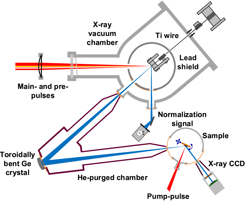
First the incoming laser beam is split into a "main-pulse" and a weaker "pre-pulse" beam by using a mirror with a hole in the center ("holey-mirror") as beam splitter. While the "main-pulse" represents the actual X-ray driver, the "pre-pulse" is used to generate a pre-plasma to enhance X-ray generation (see section III.2). After introducing a suitable delay these two beams are recombined by a second "holey-mirror" beam splitter. Before, a third beam, which serves as the "pump pulse" to excite the sample under study (seperate delay control), is split from the "main-pulse" by an off-center "holey-mirror" beam splitter.
"Main-" and "pre-pulse" are guided collinearly to a small vacuum chamber (see Fig. 1; pressure 10-2 mbar) and focused by a plano-concave lens with a focal length of 30 cm onto the surface of a Ti wire with a diameter of 250 m. The beam diameters at the focus of the lens are 25 m and 60 m for "main-" and "pre-pulse", respectively. With the given pulse energy this results in maximum intensities on the wire of close to Wcm-2 for the "main pulse" and Wcm-2 for the "pre-pulse". Due to their high intensity both pulses induce material ablation in the irradiated area and a fresh target has to be provided for each laser pulse (pair). Therefore, the wire is continously pulled over high-precision, ball-bearing mounted guides using a motor with adjustable torque installed outside the vacuum chamber, resulting in a positional stability of about 5 m in all directions.
For radiation safety purposes and in order to eliminate any hard X-ray background the wire-target assembly is enclosed by a lead-housing with minimized laser input and X-ray output openings. Additional lead shielding is attached to the inner walls of the stainless-steel vacuum chamber. Under normal operating conditions this results in a radiation level below 1 Sv/h at 10 cm distance from the chamber.
As in a conventional X-ray tube the X-ray emission of the plasma occurs spatially incoherent into the full solid angle. Therefore, suitable X-ray optics are required to collect and refocus the radiation of the plasma onto the sample under study. Here we use a toroidally bent Ge crystal in a 1:1 imaging Rowland circle geometryMissalla et al. (1999); Nicoul et al. (2005). The geometry is chosen such that the Bragg-condition is fulfilled over the whole area of the mirror resulting in very high reflectivity for a fraction of the bandwidth of the Kα-emission. As discussed in more detail below a focus with a diameter of about 80 m (FWHM), which contains up to 2 X-ray photons per pulse with a spectral bandwidth of approx. 0.43 eV centered on the Kα1 line has been achieved at our source using this mirror.
With our modular scheme only the X-ray source needs to be in vacuum to avoid non-linearities in air due to the high intensity of the focussed laser beam. The other parts of the setup (X-ray optic, sample stage, detector) are separated from the X-ray source chamber and can be flexibly moved/exchanged if required. For example, to enable experiments at low temperature a cryostat with a small sample vacuum chamber can be inserted (as schematically depicted in Fig. 1). Alternatively we use an in-air sample manipulator/goniometer for room-temperature measurements, which allows for larger or multiple samples. Since the Ti-Kα radiation at 4.51 keV is significantly absorbed in air (1/e absorption length 16 cm Henke, Gullikson, and Davis (1993)), He-purged beam tubes are placed between the different components to minimize absorption.
A thinned, back-illuminated Si CCD (Princeton Instrument PI-MTE:1300B) is used as detector for the X-rays diffracted by the sample. This detector exhibits a quantum efficiency of 55 at 4.51 keVcal and a chip area of 26.8 x26 mm2 (1340 1300 pixels of 20 20 m2 size).
To account for the variation of the X-ray flux due to both long-term drifts and short-term fluctuations Schick et al. (2012), a "direct" normalization Schick et al. (2012); Zhang et al. (2014); Höfer et al. (2016); Holtz et al. (2017) scheme has been implemented in which a GaAs crystal is properly placed at a second output of the X-ray source chamber and the integrated diffraction signal of its (111)-reflection is monitored by a large area (diameter 10 mm) X-ray sensitive avalanche photo-diode (APD). This allow to normalize the diffraction signals recorded by the CCD with an accuracy of better than 2.
The angle between the optical pump and the X-ray probe beam in combination with the finite X-ray beam size lead to a variation of the relative arrival time at the sample surface limiting the temporal resolution of the experiment. For the current geometry ( 50∘) this results in a temporal smearing of about 0.45 ps at a Bragg-angle of 20∘, which reduces to 0.2 ps for larger Bragg-angles. This is still sufficient for the investigation of transient strain effects - the application this set-up has been optimized for - which occur on acoustic, ps time-scales.
III Set-up characterization and -optimization
This section discusses the detailed characterization and optimization of the setup. This includes measurements of the source spectrum, our efforts to maximize the Kα yield, as well as the performance characterization of the bent crystal mirror in terms of efficiency, focusing capability and bandwidth.
III.1 Spectral characterization
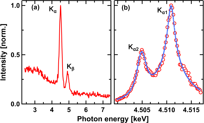
Spectral characterization has been done in two steps. First, the Si CCD was placed between the source and the bent crystal mirror and operated in photon-counting mode by drastically reducing the X-ray flux through a reduction of the drive laser power. In this mode the detector acts as a spectrometer since a single X-ray photon produces a charge in the detecting pixel that is proportional to the photon energyZamponi et al. (2005). Thus a histogram of the signals in all the pixels of the CCD represents the spectrum of the detected radiation. A typical result is shown in Fig. 2(a).
The measured spectrum is characterized by a broad continuum and two line emission features, which represent the Kα and Kβ emission of Ti. It needs to be stressed that the apparent continuum at energies below the K-shell emission lines is only partly due to Bremsstrahlung since at these photon energies there is a non-negligible probability that the charge generated by a Kα or Kβ photon is shared between two or more pixelsZamponi et al. (2005). Due to the limited energy resolution of about 150 eV, the CCD is not able to resolve spectral fine structures, namely the spin-orbit split Kα1 and Kα2 lines (energy seperation 5.98 eV). Therefore, in a second step the toroidally bent Ge crystal, which provides a spectral resolution of 0.43 eV (see section III.3), was utilized as a scanning spectrometer (by changing the incidence angle) to precisely measure the emitted Kα spectrum. As depicted in Figure 2(b), the Kα1 and Kα2 lines are completely resolved. Their width was measured as 3.1 eV, which is broader than the reported natural Ti-Kα linewidth of about 1.45 eV and 2.13 eVSalem and Lee (1976), respectively. This broadening has been observed beforeSengebusch et al. (2009); Arora et al. (2011) and attributed to emission contributions from atoms in higher ionization states.
III.2 Source optimization
As discussed before, the drive laser intensity as well as the plasma scale length have a major influence on X-ray generation and thus the Kα-flux available in a diffraction experiment.
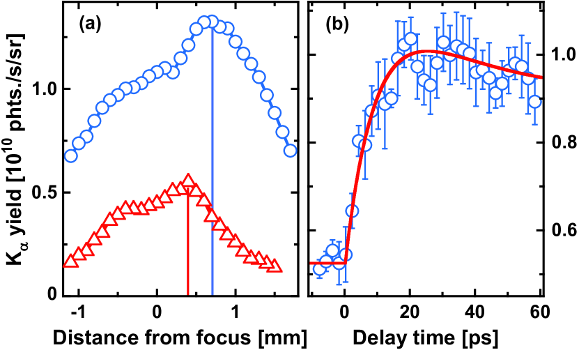
A straight-forward way to vary the intensity without changing the laser energy is to change the distance between the focusing lens and the wire, thus changing the laser spot size on the wire by moving it in and out of the focus, where the intensity is highest. The red data points in Fig. 3(a) show the total Kα yield cal as a function of the relative lens position (zero marks the position with the wire in the focus) for the case, when only the "main-pulse" is used for X-ray generation. It can be clearly seen that the maximum Kα yield is not obtained for the highest available intensity, but with the wire approx. 0.4 mm before the focus and thus at an intensity below Wcm-2. This is in agreement with previous observationsEder et al. (2000); Fill, Bayerl, and Tommasini (2002); Sokolowski-Tinten et al. (2002); Reich et al. (2003); Lu et al. (2009) and also with results of theoretical calculationsReich et al. (2000) which predict a maximum Kα yield for Ti at intensities of a few times Wcm-2.
Due to the high LPCR of the laser system used here, only a short scale length pre-plasma is created by the leading edge of a single pulse. Therefore, the collisionless coupling of laser energy to the plasma and consequently the X-ray production is not optimum Gibbon and Bell (1992). We have shown previouslyLu et al. (2009) that it is possible to maximize the Kα flux by creating a pre-plasma with the angle of incidence-dependent optimum plasma scale length using a controlled "pre-pulse" with a suitable negative delay with respect to the X-ray generating "main-pulse". We apply this approach here. The "pre-pulse" had a maximum intensity of almost Wcm-2 with the wire in the focus of the lens. The measured Kα yield versus delay time is depicted in Fig. 3(b). Positive delay times mean that the pre-pulse arrives earlier than the main-pulse, so the plasma scale length increases with delay time. As expected, the Kα flux is enhanced at positive delays, when the plasma generated by the pre-pulse has expanded. A maximum yield increase of about a factor of two is reached at approximately 20 ps. In line with our previous resultsLu et al. (2009) a relatively long scale length pre-plasma and thus a long delay between pre- and main-pulse is required due to the near-normal incidence of the laser on the wire, which has been chosen to minimize the effects of fluctuations of the wire position as well as the laser pointing.
The data shown in Fig. 3(b) have been measured at the lens position which resulted in maximum Kα production without the "pre-pulse".cal As illustrated by the blue data points in Fig. 3(a) we were able to improve the X-ray yield with "pre-pulse" further by reducing the intensity of both, the "pre-" and the "main-pulse", through an increase of the wire-focus distance. At optimum conditions a maximum Ti Kα flux of more than photons s-1 sr-1 was achieved, which corresponds to photons per pulse delivered to the sample.
III.3 X-Ray optics
Almost at any X-ray source X-ray optical elements are used to direct, focus or more generally manipulate the radiation for an intended application. For example at accelerator based X-ray sources like synchrotrons and X-ray free electron lasers, which usually exhibit well collimated and often highly monochromatic beams, lenses Lengeler et al. (2005) as well as curved mirrors based on total reflection at grazing incidence Yumoto et al. (2012) are employed. In contrast, the spatially incoherent 4-emission of laser-plasma based X-ray sources require optics, which allow to collect the radiation over a sufficiently large solid angle and deliver it to the sample in a suitably shaped beam (focused, collimated). Bent crystals, multi-layer mirrors and capillary optics have been utilized for this purposeMissalla et al. (1999); Nicoul et al. (2005); Bargheer et al. (2005); Shymanovich et al. (2008); Rathore et al. (2017); Schollmeier et al. (2018).
Among those, bent crystals provide the highest spectral purityBargheer et al. (2005). Since the spectral bandwidth determines the angular/momentum resolution of a diffraction experiment, such an optic has been chosen for the current set-up. They are based on Bragg diffraction and can achieve a high reflectivity over a large area, since the lattice planes are parallel to the geometrical surface of the either spherically or toroidally bent crystalsMissalla et al. (1999).
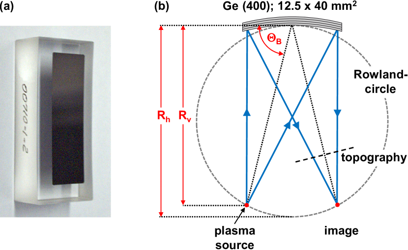
In the current setup we employ the (400)-reflection of a toroidally bent Ge-crystal with (100)-orientation. It has been fabricated by INRAD inc.INRAD Optics to our specifications and technical details have been discussed by Nicoul et al.Nicoul et al. (2005). In brief, a 12.5 mm wide, 40 mm high, and 90 m thick Ge crystal is bound to a toroidally shaped glass substrate (see photograph in Fig. 4(a)). Such a toroidally bent crystal mirror provides a quasi-monochromatic 1:1 image of a point-like source if source and image are located on the so-called Rowland-circle, as depicted in Fig. 4(b), such that the vertical and horizontal bending radii and , respectively, satisfy the condition , with being the Bragg angle for the required X-ray wavelength (here for Ti Kα1).
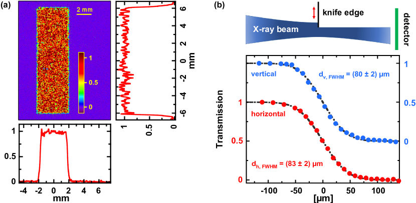
To ensure both, highest mononchromaticity and a homogeneous reflectivity across the mirror surface the source needs to be accurately positioned on the Rowland-cicle. Therefore, the source-mirror distance as well as the Bragg-angle (see also Fig. 2(b)) have been carefully adjusted by monitoring the intensity distribution of the reflected/diffracted Kα radiation with the X-ray CCD placed between mirror and sample/image position (marked by the dashed line labelled as "topography" in Fig. 4(b)). Figure 5(a) shows the reflectivity distribution and its vertically and horizontally averaged cross-sections for optimum adjustment. Despite fluctuations resulting from the short detector integration time (corresponding to a relatively low average number of photons per pixel), these data evidence a homogeneous reflectivity across the entire mirror surface. In the image plane ("focus" of the X-ray mirror) this transfers into a monochromatic and homogeneous intensity distribution as a function of angle over the full convergence range of 1.4∘ in horizontal direction (the dispersion direction of our set-up) and 4.5∘ vertically. In this configuration the complete angular dependence of the diffraction signal of a sample, i. e. its rocking curve, can be obtained without actually rocking (rotating) the sample.
Another critical point for optical pump - X-ray probe experiments concerns the exact determination of the focus/image position of such a mirror, because severe distortions of the angular distribution of the X-rays diffracted off the laser-excited area can occur if the sample under study is not properly positioned in the focus.Shymanovich et al. (2007) To precisely localize the focus, knife-edge scans using blades mounted on the sample stage exactly in the plane of the sample surface have been performed for different distances between mirror and sample (see top schematic in Fig. 5(b)). Results of such knife-edge scans for the best focus are depicted in the bottom part of Fig. 5(b), which shows the normalized "transmitted" signal as a function of the position of the horizontal (red) and vertical (blue) blade, respectively. The measured data can be described very well by an error function (black dashed-dotted curves), where corresponds to the -radius of a Gaussian beam. From these fits we determine the focus/image diameter (FWHM) to 83 2 m and 80 2 m in horizontal and vertical direction, respectively. This size represents the convolution between the imaging properties of the bent mirror and the X-ray source size (which we have not measured here) and is small enough to allow for a sufficient pump-probe spot size ratio.
III.4 Static and Dynamic Diffraction
In this section we present the results of static (without laser pumping) and time-resolved (with laser pumping) diffraction measurements to discuss treatment of the diffraction data, to characterize the angular/momentum resolution of the experiment, and to demonstrate the overall performance and sensitivity of the setup. For this purpose two different samples have been investigated, namley a (100)-oriented bulk GaAs crystal and a 180 nm thick, (111)-oriented Ge film, hetero-epitaxially grown on a (111)-oriented bulk Si substrate.Horn-von Hoegen et al. (1994)
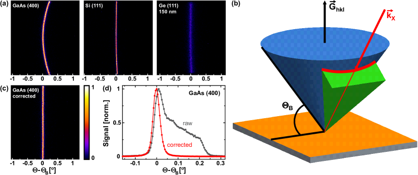
Fig. 6(a) (top panel) shows raw detector images of (i) the (400)-reflection of the GaAs crystal, (ii) the (111)-reflection of the Si substrate, and (iii) the (111)-reflection of the 180 nm thick Ge film on-top the Si crystal, all obtained with an integration time of 1 minute (600 X-ray pulses) and without optical pumping. With an incident X-ray flux of about Kα photons per pulse the detected integrated diffraction signal in photons per pulse is 240, 90, and 60 for the GaAs (400), Si (111), and Ge (111) reflections, respectively.
All diffraction patterns exhibit the shape of curved lines (most pronounced for the GaAs (400)). This is caused by the fact that a X-ray "beam" with a large convergence (1.4∘ horizonatlly and 4.5∘ vertically) is used. As depicted schematically in Fig. 6(b) all possible incident and diffracted X-rays for a particular reflection (hkl) lie on the so-called Kossel-cone (blue), which has a full opening angle of and an axis along the reciprocal lattice vector . From the Kossel-cone the X-rays (with center ray ) focused by the bent mirror onto the sample surface (marked green in Fig. 6(b)) cut out a curved, line-shaped segment (red). Since the opening angle of the Kossel-cone decreases with increasing Bragg-angle the curvature of the diffraction pattern is strongest for the (400)-reflection of GaAs (Bragg-angle of 76.4∘).
In these images the horizontal axis corresponds to the "dispersive" direction and rocking curves are, in principle, obtained as horizontal cross sections after vertical integration of the diffraction pattern. However, the bending of the diffraction pattern lead to distortions of the rocking curves. Therefore, to achieve the highest possible angular resolution, we applied a bending correction by fitting the curved diffraction line by a parabola which is then used to "unbend" the whole pattern, e.g. Fig. 6(c). The effect as well as the necessity for this bending correction is illustrated by Fig. 6(d), which shows the rocking curve of the GaAs (400) reflection without (grey curve) and with (red curve) bending correction. The rocking curve obtained from the uncorrected diffraction pattern is broadened and strongly asymmetrically deformed compared to the corrected case.
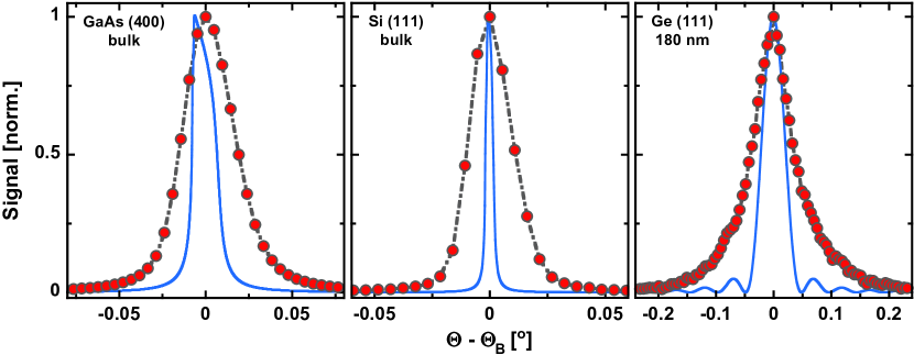
Fig. 7 shows (red-gray) the rocking curves derived from the measured diffraction pattern in Fig. 6 after bending correction. The experimental curves are compared to calculated rocking curves (blue) using the the XCrystal-routine from the XOP-packageManuel Sanchez del Rio (1997) (ver. 2.3).
It is obvious that all experimental curves exhibit a larger width than the curves calculated for perfect crystals and a strictly monochromatic and fully collimated X-ray beam. The experimental rocking curve width has three different contributions, namely due to the finite X-ray spot size (converted into angle) on the sample , due to the bandwidth of the radiation reflected by the bent mirror , and due to the "natural" rocking curve width of the corresponding reflection (polarization averaged). We assume here .
Commercial wafers of GaAs and Si, as have been used here, exhibit almost perfect crystalline structure. Therefore their "natural" rocking curve should be close to the calculated ones. For the Si (111)-reflection we measure an angular width of 0.022∘ corresponding to 4 pixels or 80 m on the detector and thus equal to the measured X-ray spot size on the sample (compare Fig. 5(b)). In this case the contributions from the natural rocking curve width 0.003∘ and the bandwidth 0.003∘ (see below) are negligible. In contrast, for the case of the thin Ge-film dominates the overall width. However, the measured width of 0.074∘ is significantly larger than the width of the calculated rocking curve (0.04∘). Moreover, the experimental rocking curve lacks the thickness fringes of the calculated curve. We attribute both observations to a finite mosaic spread in the hetero-epitaxially grown film. Finally, for the GaAs (400)-reflection, all three effects contribute similarly, which allows to determine the spectral bandwidth of the radiation reflected by the mirror. With a total width of 0.034∘, a spot size contribution of 0.019∘, and a "natural" rocking curve width of 0.015∘, a bandwidth contribution of 0.023∘ is obtained. This results in an energy bandwidth of eV ( = 76.5∘ GaAs (400) Bragg angle, 4.51 keV X-ray photon energy) or a relative bandwith of 10-4. This bandwidth is comparable, but larger than the "natural" bandwidth of the Ge (400)-reflection of a plane crystal of 0.27 eV. We attribute this to slight strain effects in the bent crystal, which will increase its bandwidth and decrease the peak reflectivity.Uschmann et al. (1993)
With the mirror bandwidth 0.43 eV, its acceptance solid angle sr, assuming a polarization-averaged peak reflectivity (chosen somewhat smaller than the value of 0.92 for the plane crystal), and the measured Ti-Kα1 linewidth of 3.1 eV we can derive the mirror efficiency as (this value has been used to estimate the total -yield of our plasma X-ray source; see sec. III.2).
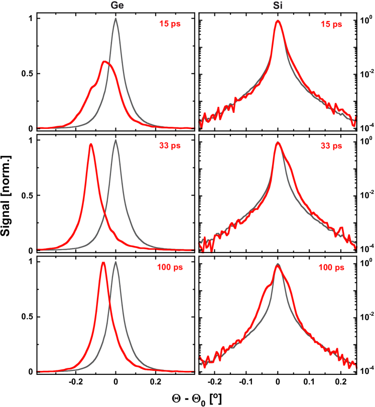
We finally present here exemplary time-resolved data obtained on the Ge/Si heterostructure after optical excitation of the Ge top layer with 100 fs, 800 nm laser pulses. Fig. 8 shows the measured transient rocking curves (red) of the (111)-reflection of the 180 nm Ge overlayer (left column, linear scale) and the (111)-reflection of the bulk Si-substrate (right column, logarithmic scale) for three different pump-probe time delays. The grey curves represent the corresponding rocking curves of the unexcited sample measured at a pump-probe time delay of -15 ps, i.e. before arrival of the optical pump.
For the Ge film we observe a shift and broadening of the whole rocking curve towards smaller diffraction angles, indicating (an initially inhomogeneous) expansion of the lattice. In contrast, the main peak of the Si-rocking curve remains essentially unchanged, but develops shoulders, initially only on the high angle side (indicating compression), but later also on the low-angle side (indicating expansion). This behavior can be explained by strain wavesThomsen et al. (1986), which are triggered by the almost instantaneous increase of stress/pressure in the Ge-film upon its electronic excitation as well as the subsequent lattice heating.
Initially rarefaction waves are launched at both boundaries of the Ge film (the free surface as well as the Ge-Si interface), which propagate back and forth in the Ge-film while being partially transmitted into the Si-substrate on each round-trip. Expansion of the Ge-film is evidenced by the overall shift (and broadening) of the rocking curves towards smaller diffraction angles. This expansion leads to a compression of the Si substrate (shoulder of the Si rocking curve on the high angle side for 15 ps and 33 ps). At later times a train of bi-polar strain pulsesThomsen et al. (1986); Rose-Petruck et al. (1999); Shymanovich et al. (2009) develops resulting in shoulders/sattellites on both sides of the main Si (111)-peak.
The detailed strain evolution is determined by the complex interplay of electronic and thermal stress contributions,Thomsen et al. (1986) which, as our measurements reveal, exhibit pronounced temporal and fluence dependencies. This we attribute to the dependence of the effective deformation potential, which determines the magnitude of the electronic stress, on the fluence- and time-dependent density of the laser-excited electron-hole plasma. While a detailed discussion of these processes is beyond the scope of this paper and will be presented in a separate publicationAfshari et al. (2019), we would like to stress that the high dynamic range (best visible for the logarithmically presented Si-data) of almost 104, enabled us to monitor even subtle changes of the rocking curves with high sensitivity and was key to separate and quantify the different stress contributions.
IV Discussion and Summary
In summary, we have presented here a modular set-up for time-resolved "optical-pump - X-ray-probe" diffraction experiments which is based on a low repetition rate (10 Hz), laser-driven plasma Kα X-ray source. X-ray production with Ti as target material has been optimized by carefully adjusting the laser intensity as well as by employing a "pre-pulse"-scheme resulting in a total Ti Kα (4.51 keV) flux of up to photons per second into the full solid angle. By using a toroidally bent Ge (100) crystal to collect and refocus the Kα emission of the plasma, narrow bandwidth (0.43 eV; relative) radiation with photons per second and a small spot size of 80 m (FWHM) can be delivered to the sample. Table 1 summarizes the characteristics of the set-up.cal
| Parameter | Value |
|---|---|
| Laser wavelength | 800 nm |
| Laser pulse duration | 100 fs |
| Repetition rate | 10 Hz |
| "Main-pulse" intensity (max.) / diameter (focus) | Wcm-2 / 25 m (FWHM) |
| "Pre-pulse" intensity (max.)/ diameter (focus) | Wcm-2 / 60 m (FWHM) |
| Optimum delay between "main-" and "pre-pulse" | 20 ps |
| Ti-Kα yield | 1.3 photons s-1 sr-1 |
| Bent mirror spectral bandwidth / relative bandwidth111centered at Ti-Kα1 4.51 keV. | 0.43 eV / 10-4 |
| Bent mirror efficiency | 1.8 |
| X-ray convergence angle (hor. / vert.) | 1.4∘ / 4.5∘ |
| X-ray focal spot diameter | 80 m (FWHM) |
| Average X-ray spectral brightnessMills et al. (2005) (in the focus) | 2 |
| photons s-1 mm-2 mrad-2 (0.1 bandwidth)-1 |
The current configuration, by using the bent crystal optics, allows experiments with high angular/momentum resolution and is - as demonstrated by the data presented in Fig. 8 - well suited to monitor transient changes of rocking curves. However, the modular approach provides a high flexibility to adopt the set-up to specific requirements of a particular experiment/application: (i) The target material defines the X-ray photon energy and we use our wire-source also with Cu (EKα = 8.05 keV) since suitable X-ray optics (bent crystalsNicoul et al. (2005), multilayer opticsBargheer et al. (2005); Shymanovich et al. (2008)) are available. (ii) Using multi-layer optics, which exhibit a significantly larger bandwidth (i.e. full Kα emission) we can expect with our current source an almost an order-of-magnitude higher Kα photon flux on the sample. Such a configuration can be used when the shape and position of the rocking curve does not change, but only the diffraction intensity due to structure factor changes (e.g. caused by the excitation of optical phononsSokolowski-Tinten et al. (2003); Fritz et al. (2007)). (iii) Also the sample environment can be flexibly changed to allow for example measurements at low temperatures (cryostat) or the study of irreversible dynamics (e.g. meltingSiders et al. (1999); Rousse et al. (2001); Sokolowski-Tinten et al. (2001)) which require a sample manipulator/goniometer for large samples ( 10 cm) and rapid sample motion since a fresh sample area has to be provided for each pulse.
It also needs be stressed that many other laser plasma X-ray sources employ few-mJ, kHz repetition rate laser systems and achieve a similar average X-ray flux. In contrast, we use a high pulse energy (> 100 mJ), low repetition rate drive laser, which results in a two orders of magnitude higher per-pulse X-ray flux. Therefore, a correspondingly lower number of X-ray probe- and optical pump cycles is required to obtain time-resolved diffraction data with a similar integrated signal. This reduction of the optical "dose" is critical for the above mentioned studies of irreversible dynamics since sample area is usually limited and more generally when working in an excitation regime where accumulative sample damage becomes an issue.
Acknowledgements.
Financial support by the Deutsche Forschungsgemeinschaft (DFG, German Research Foundation) through project C01 Structural Dynamics in Impulsively Excited Nanostructures of the Collaborative Research Center SFB 1242 Non-Equilibrium Dynamics of Condensed Matter in the Time Domain (project number 278162697) is gratefully acknowledged. The authors thank M. Horn-von Hoegen, M. Kammler, and T. Wietler for providing the Ge-Si-heterostructure used in this work.References
- Elsaesser and Woerner (2014) T. Elsaesser and M. Woerner, “Perspective: Structural dynamics in condensed matter mapped by femtosecond x-ray diffraction,” The Journal of Chemical Physics 140, 020901 (2014) .
- Miller (2014) R. J. D. Miller, “Femtosecond crystallography with ultrabright electrons and x-rays: Capturing chemistry in action,” Science 343, 1108 (2014) .
- Weathersby et al. (2015) S. P. Weathersby, G. Brown, M. Centurion, T. F. Chase, R. Coffee, J. Corbett, J. P. Eichner, J. C. Frisch, A. R. Fry, M. Gühr, N. Hartmann, C. Hast, R. Hettel, R. K. Jobe, E. N. Jongewaard, J. R. Lewandowski, R. K. Li, A. M. Lindenberg, I. Makasyuk, J. E. May, D. McCormick, M. N. Nguyen, A. H. Reid, X. Shen, K. Sokolowski-Tinten, T. Vecchione, S. L. Vetter, J. Wu, J. Yang, H. A. Dürr, and X. J. Wang, “Mega-electron-volt ultrafast electron diffraction at slac national accelerator laboratory,” Review of Scientific Instruments 86, 073702 (2015).
- Schoenlein et al. (2019) R. Schoenlein, T. Elsaesser, K. Holldack, Z. Huang, H. Kapteyn, M. Murnane, and M. Woerner, “Recent advances in ultrafast x-ray sources,” Philosophical Transactions of the Royal Society A: Mathematical, Physical and Engineering Sciences 377, 20180384 (2019) .
- Bostedt et al. (2016) C. Bostedt, S. Boutet, D. M. Fritz, Z. Huang, H. J. Lee, H. T. Lemke, A. Robert, W. F. Schlotter, J. J. Turner, and G. J. Williams, “Linac coherent light source: The first five years,” Rev. Mod. Phys. 88, 015007 (2016).
- Krol et al. (1997) A. Krol, A. Ikhlef, J. C. Kieffer, D. A. Bassano, C. C. Chamberlain, Z. Jiang, H. Pépin, and S. C. Prasad, “Laser-based microfocused x-ray source for mammography: Feasibility study,” Medical Physics 24, 725 (1997).
- Toth et al. (2007) R. Toth, S. Fourmaux, T. Ozaki, M. Servol, J. C. Kieffer, R. E. Kincaid, and A. Krol, “Evaluation of ultrafast laser-based hard x-ray sources for phase-contrast imaging,” Physics of Plasmas 14, 053506 (2007).
- Chen et al. (2010) L. Chen, W. Wang, M. Kando, L. Hudson, F. Liu, X. Lin, J. Ma, Y. Li, S. Bulanov, T. Tajima, Y. Kato, Z. Sheng, and J. Zhang, “High contrast femtosecond laser-driven intense hard x-ray source for imaging application,” Nuclear Instruments and Methods in Physics Research Section A: Accelerators, Spectrometers, Detectors and Associated Equipment 619, 128 (2010), Frontiers in radiation physics and applications: Proceedings of the 11th International Symposium on Radiation Physics.
- Ráksi et al. (1996) F. Ráksi, K. R. Wilson, Z. Jiang, A. Ikhlef, C. Y. Côté, and J. Kieffer, “Ultrafast x-ray absorption probing of a chemical reaction,” The Journal of Chemical Physics 104, 6066 (1996).
- Reich et al. (2007) C. Reich, C. M. Laperle, X. Li, B. Ahr, F. Benesch, and C. G. Rose-Petruck, “Ultrafast x-ray pulses emitted from a liquid mercury laser target,” Opt. Lett. 32, 427 (2007).
- Dorchies et al. (2011) F. Dorchies, A. Lévy, C. Goyon, P. Combis, D. Descamps, C. Fourment, M. Harmand, S. Hulin, P. M. Leguay, S. Petit, O. Peyrusse, and J. J. Santos, “Unraveling the solid-liquid-vapor phase transition dynamics at the atomic level with ultrafast x-ray absorption near-edge spectroscopy,” Phys. Rev. Lett. 107, 245006 (2011).
- Miaja-Avila et al. (2016) L. Miaja-Avila, G. C. O’Neil, Y. I. Joe, B. K. Alpert, N. H. Damrauer, W. B. Doriese, S. M. Fatur, J. W. Fowler, G. C. Hilton, R. Jimenez, C. D. Reintsema, D. R. Schmidt, K. L. Silverman, D. S. Swetz, H. Tatsuno, and J. N. Ullom, “Ultrafast time-resolved hard x-ray emission spectroscopy on a tabletop,” Phys. Rev. X 6, 031047 (2016).
- Anwar et al. (2019) M. I. Anwar, M. Iqbal, B. J. Hwang, M. Faiyaz, B. S. Mun, K. A. Janulewicz, and D. Y. Noh, “Ultrafast x-ray absorption near edge spectroscopy of fe3o4 using a laboratory based femtosecond x-ray source,” Opt. Express 27, 6030 (2019).
- Rose-Petruck et al. (1999) C. Rose-Petruck, R. Jimenez, T. Guo, A. Cavalleri, C. W. Siders, F. Rksi, J. A. Squier, B. C. Walker, K. R. Wilson, and C. P. J. Barty, “Picosecond–milliångström lattice dynamics measured by ultrafast x-ray diffraction,” Nature 398, 310 (1999).
- Siders et al. (1999) C. W. Siders, A. Cavalleri, K. Sokolowski-Tinten, C. Tóth, T. Guo, M. Kammler, M. H. v. Hoegen, K. R. Wilson, D. v. d. Linde, and C. P. J. Barty, “Detection of nonthermal melting by ultrafast x-ray diffraction,” Science 286, 1340 (1999).
- Rousse et al. (2001) A. Rousse, C. Rischel, S. Fourmaux, I. Uschmann, S. Sebban, G. Grillon, P. Balcou, E. Förster, J. P. Geindre, P. Audebert, J. C. Gauthier, and D. Hulin, “Non-thermal melting in semiconductors measured at femtosecond resolution,” Nature 410, 65 (2001).
- Sokolowski-Tinten et al. (2001) K. Sokolowski-Tinten, C. Blome, C. Dietrich, A. Tarasevitch, M. Horn von Hoegen, D. von der Linde, A. Cavalleri, J. Squier, and M. Kammler, “Femtosecond x-ray measurement of ultrafast melting and large acoustic transients,” Phys. Rev. Lett. 87, 225701 (2001).
- Sokolowski-Tinten et al. (2003) K. Sokolowski-Tinten, C. Blome, J. Blums, A. Cavalleri, C. Dietrich, A. Tarasevitch, I. Uschmann, E. Förster, M. Kammler, M. Horn-von Hoegen, and D. von der Linde, “Femtosecond x-ray measurement of coherent lattice vibrations near the lindemann stability limit,” Nature 422, 287 (2003).
- Bargheer et al. (2004) M. Bargheer, N. Zhavoronkov, Y. Gritsai, J. C. Woo, D. S. Kim, M. Woerner, and T. Elsaesser, “Coherent atomic motions in a nanostructure studied by femtosecond x-ray diffraction,” Science 306, 1771 (2004),.
- Korff Schmising et al. (2007) C. v. Korff Schmising, M. Bargheer, M. Kiel, N. Zhavoronkov, M. Woerner, T. Elsaesser, I. Vrejoiu, D. Hesse, and M. Alexe, “Coupled ultrafast lattice and polarization dynamics in ferroelectric nanolayers,” Phys. Rev. Lett. 98, 257601 (2007).
- Quirin et al. (2012) F. Quirin, M. Vattilana, U. Shymanovich, A.-E. El-Kamhawy, A. Tarasevitch, J. Hohlfeld, D. von der Linde, and K. Sokolowski-Tinten, “Structural dynamics in FeRh during a laser-induced metamagnetic phase transition,” Phys. Rev. B 85, 020103 (2012).
- Stingl et al. (2012) J. Stingl, F. Zamponi, B. Freyer, M. Woerner, T. Elsaesser, and A. Borgschulte, “Electron transfer in a virtual quantum state of induced by strong optical fields and mapped by femtosecond x-ray diffraction,” Phys. Rev. Lett. 109, 147402 (2012).
- Juvé et al. (2013) V. Juvé, M. Holtz, F. Zamponi, M. Woerner, T. Elsaesser, and A. Borgschulte, “Field-driven dynamics of correlated electrons in LiH and revealed by femtosecond x-ray diffraction,” Phys. Rev. Lett. 111, 217401 (2013).
- Pudell et al. (2018) J. Pudell, A. A. Maznev, M. Herzog, M. Kronseder, C. H. Back, G. Malinowski, A. von Reppert, and M. Bargheer, “Layer specific observation of slow thermal equilibration in ultrathin metallic nanostructures by femtosecond x-ray diffraction,” Nature Communications 9, 3335 (2018).
- Rischel et al. (1997) C. Rischel, A. Rousse, I. Uschmann, P.-A. Albouy, J.-P. Geindre, P. Audebert, J.-C. Gauthier, E. Fröster, J.-L. Martin, and A. Antonetti, “Femtosecond time-resolved x-ray diffraction from laser-heated organic films,” Nature 390, 490 (1997).
- Gibbon (2005) P. Gibbon, Short Pulse Laser Interactions with Matter: An Introduction (Imperial College Press, 2005).
- Kühlke, Herpers, and von der Linde (1987) D. Kühlke, U. Herpers, and D. von der Linde, “Soft x-ray emission from subpicosecond laser-produced plasmas,” Applied Physics Letters 50, 1785 (1987).
- Murnane et al. (1991) M. M. Murnane, H. C. Kapteyn, M. D. Rosen, and R. W. Falcone, “Ultrafast x-ray pulses from laser-produced plasmas,” Science 251, 531 (1991).
- Brunel (1987) F. Brunel, “Not-so-resonant, resonant absorption,” Phys. Rev. Lett. 59, 52 (1987).
- Gibbon and Bell (1992) P. Gibbon and A. R. Bell, “Collisionless absorption in sharp-edged plasmas,” Phys. Rev. Lett. 68, 1535 (1992).
- Teubner et al. (1993) U. Teubner, J. Bergmann, B. van Wonterghem, F. P. Schäfer, and R. Sauerbrey, “Angle-dependent x-ray emission and resonance absorption in a laser-produced plasma generated by a high intensity ultrashort pulse,” Phys. Rev. Lett. 70, 794 (1993).
- Teubner et al. (1996) U. Teubner, P. Gibbon, E. Förster, F. Falliès, P. Audebert, J. P. Geindre, and J. C. Gauthier, “Subpicosecond KrF*-laser plasma interaction at intensities between and W/cm2,” Physics of Plasmas 3, 2679 (1996).
- Teubner, Theobald, and Wülker (1996) U. Teubner, W. Theobald, and C. Wülker, “Mechanisms and origin of continuum and line emission from carbon plasmas produced by ultrashort laser pulses,” Journal of Physics B: Atomic, Molecular and Optical Physics 29, 4333 (1996).
- Reich et al. (2000) C. Reich, P. Gibbon, I. Uschmann, and E. Förster, “Yield optimization and time structure of femtosecond laser plasma sources,” Phys. Rev. Lett. 84, 4846 (2000).
- Ziener et al. (2002) C. Ziener, I. Uschmann, G. Stobrawa, C. Reich, P. Gibbon, T. Feurer, A. Morak, S. Düsterer, H. Schwoerer, E. Förster, and R. Sauerbrey, “Optimization of Kα bursts for photon energies between 1.7 and 7 keV produced by femtosecond-laser-produced plasmas of different scale length,” Phys. Rev. E 65, 066411 (2002).
- Reich et al. (2003) C. Reich, I. Uschmann, F. Ewald, S. Düsterer, A. Lübcke, H. Schwoerer, R. Sauerbrey, E. Förster, and P. Gibbon, “Spatial characteristics of x-ray emission from relativistic femtosecond laser plasmas,” Phys. Rev. E 68, 056408 (2003).
- Weisshaupt et al. (2015) J. Weisshaupt, V. Juvé, M. Holtz, M. Woerner, and T. Elsaesser, “Theoretical analysis of hard x-ray generation by nonperturbative interaction of ultrashort light pulses with a metal,” Structural Dynamics 2, 024102 (2015).
- Rousse et al. (1994) A. Rousse, P. Audebert, J. P. Geindre, F. Falliès, J. C. Gauthier, A. Mysyrowicz, G. Grillon, and A. Antonetti, “Efficient Kα x-ray source from femtosecond laser-produced plasmas,” Phys. Rev. E 50, 2200 (1994).
- Zamponi et al. (2010) F. Zamponi, Z. Ansari, M. Woerner, and T. Elsaesser, “Femtosecond powder diffraction with a laser-driven hard x-ray source,” Opt. Express 18, 947 (2010).
- Powell (1976) C. J. Powell, “Cross sections for ionization of inner-shell electrons by electrons,” Rev. Mod. Phys. 48, 33 (1976).
- Ewald, Schwoerer, and Sauerbrey (2002) F. Ewald, H. Schwoerer, and R. Sauerbrey, “-radiation from relativistic laser-produced plasmas,” EPL (Europhysics Letters) 60, 710 (2002).
- Eder et al. (2000) D. C. Eder, G. Pretzler, E. Fill, K. Eidmann, and A. Saemann, “Spatial characteristics of Kα radiation from weakly relativistic laser plasmas,” Appl. Phys. B 70, 211 (2000).
- Meyerhofer et al. (1993) D. D. Meyerhofer, H. Chen, J. A. Delettrez, B. Soom, S. Uchida, and B. Yaakobi, “Resonance absorption in high-intensity contrast, picosecond laser–plasma interactions,” Physics of Fluids B: Plasma Physics 5, 2584 (1993).
- Jiang et al. (1995) Z. Jiang, J. C. Kieffer, J. P. Matte, M. Chaker, O. Peyrusse, D. Gilles, G. Korn, A. Maksimchuk, S. Coe, and G. Mourou, “X-ray spectroscopy of hot solid density plasmas produced by subpicosecond high contrast laser pulses at – W/cm2,” Physics of Plasmas 2, 1702 (1995).
- Gibbon and Förster (1996) P. Gibbon and E. Förster, “Short-pulse laser - plasma interactions,” Plasma Physics and Controlled Fusion 38, 769 (1996).
- Feurer et al. (2001) T. Feurer, A. Morak, I. Uschmann, C. Ziener, H. Schwoerer, E. Förster, and R. Sauerbrey, “An incoherent sub-picosecond x-ray source for time-resolved x-ray-diffraction experiments,” Appl. Phys. B 72, 15 (2001).
- Weisshaupt et al. (2014) J. Weisshaupt, V. Juvé, M. Holtz, S. Ku, M. Woerner, T. Elsaesser, S. Ališauskas, A. Pugžlys, and A. Baltuška, “High-brightness table-top hard x-ray source driven by sub-100-femtosecond mid-infrared pulses,” Nat. Photonics 8, 927 (2014).
- Fourmaux and Kieffer (2016) S. Fourmaux and J. C. Kieffer, “Laser-based Kα x-ray emission characterization using a high contrast ratio and high-power laser system,” Appl. Phys. B 122, 162 (2016).
- Azamoum et al. (2018a) Y. Azamoum, R. Clady, A. Ferré, M. Gambari, O. Utéza, and M. Sentis, “High photon flux Kα Mo x-ray source driven by a multi-terawatt femtosecond laser at 100 Hz,” Opt. Lett. 43, 3574 (2018a).
- Azamoum et al. (2018b) Y. Azamoum, V. Tcheremiskine, R. Clady, A. Ferré, L. Charmasson, O. Utéza, and M. Sentis, “Impact of the pulse contrast ratio on Molybdenum Kα generation by ultrahigh intensity femtosecond laser solid interaction,” Scientific Reports 8, 4119 (2018b).
- Zhavoronkov et al. (2005) N. Zhavoronkov, Y. Gritsai, M. Bargheer, M. Woerner, and T. Elsaesser, “Generation of ultrashort Kα radiation from quasipoint interaction area of femtosecond pulses with thin foils,” Applied Physics Letters 86, 244107 (2005).
- Khattak et al. (2006) F. Y. Khattak, O. A. M. B. Percie du Sert, D. Riley, P. S. Foster, E. J. Divall, C. J. Hooker, A. J. Langley, J. Smith, and P. Gibbon, “Comparison of experimental and simulated Kα yield for 400 nm ultrashort pulse laser irradiation,” Phys. Rev. E 74, 027401 (2006).
- Bastiani et al. (1997) S. Bastiani, A. Rousse, J. P. Geindre, P. Audebert, C. Quoix, G. Hamoniaux, A. Antonetti, and J. C. Gauthier, “Experimental study of the interaction of subpicosecond laser pulses with solid targets of varying initial scale lengths,” Phys. Rev. E 56, 7179 (1997).
- Schlegel et al. (1999) T. Schlegel, S. Bastiani, L. Grémillet, J.-P. Geindre, P. Audebert, J.-C. Gauthier, E. Lefebvre, G. Bonnaud, and J. Delettrez, “Comparison of measured and calculated x-ray and hot-electron production in short-pulse laser-solid interactions at moderate intensities,” Phys. Rev. E 60, 2209 (1999).
- Nakano, Nishikawa, and Uesugi (2001) H. Nakano, T. Nishikawa, and N. Uesugi, “Enhanced K-shell x-ray line emissions from aluminum plasma created by a pair of femtosecond laser pulses,” Applied Physics Letters 79, 24 (2001).
- Sokolowski-Tinten et al. (2002) K. Sokolowski-Tinten, C. Blome, J. Blums, A. Cavalleri, C. Dietrich, A. Tarasevitch, and D. von der Linde, “Ultrafast time-resolved x-ray diffraction,” AIP Conf. Proc. 634, 11 (2002) .
- Lu et al. (2009) W. Lu, M. Nicoul, U. Shymanovich, A. Tarasevitch, P. Zhou, K. Sokolowski-Tinten, D. von der Linde, M. Mašek, P. Gibbon, and U. Teubner, “Optimized Kα x-ray flashes from femtosecond-laser-irradiated foils,” Phys. Rev. E 80, 026404 (2009).
- Missalla et al. (1999) T. Missalla, I. Uschmann, E. Förster, G. Jenke, and D. von der Linde, “Monochromatic focusing of subpicosecond x-ray pulses in the keV range,” Review of Scientific Instruments 70, 1288 (1999),.
- Nicoul et al. (2005) M. Nicoul, U. Shymanovich, S. Kähle, T. Caughey, D. Sampat, K. Sokolowski-Tinten, and D. von der Linde, “Bent crystal x-ray mirrors for time-resolved experiments with femtosecond laser-produced x-ray pulses,” J. Phys. Conf. Ser. 21, 207 (2005).
- Henke, Gullikson, and Davis (1993) B. Henke, E. Gullikson, and J. Davis, “X-ray interactions: photoabsorption, scattering, transmission, and reflection at E=50-30000 eV, Z=1-92,” Atomic Data and Nuclear Data Tables 52, 181 (1993).
- (61) The quantum efficiency of the CCD was measured with a calibrated Si reference detector (Amptek XR100-CR).
- Schick et al. (2012) D. Schick, A. Bojahr, M. Herzog, C. v. K. Schmising, R. Shayduk, W. Leitenberger, P. Gaal, and M. Bargheer, “Normalization schemes for ultrafast x-ray diffraction using a table-top laser-driven plasma source,” Review of Scientific Instruments 83, 025104 (2012),.
- Zhang et al. (2014) B. B. Zhang, S. S. Sun, D. R. Sun, and Y. Tao, “Note: A novel normalization scheme for laser-based plasma x-ray sources,” Review of Scientific Instruments 85, 096110 (2014),.
- Höfer et al. (2016) S. Höfer, T. Kämpfer, E. Förster, T. Stöhlker, and I. Uschmann, “Communication: The formation of rarefaction waves in semiconductors after ultrashort excitation probed by grazing incidence ultrafast time-resolved x-ray diffraction,” Structural Dynamics 3, 051101 (2016).
- Holtz et al. (2017) M. Holtz, C. Hauf, J. Weisshaupt, A.-A. H. Salvador, M. Woerner, and T. Elsaesser, “Towards shot-noise limited diffraction experiments with table-top femtosecond hard x-ray sources,” Structural Dynamics 4, 054304 (2017).
- Zamponi et al. (2005) F. Zamponi, T. Kämpfer, A. Morak, I. Uschmann, and E. Förster, “Characterization of a deep depletion, back-illuminated charge-coupled device in the x-ray range,” Review of Scientific Instruments 76, 116101 (2005).
- Salem and Lee (1976) S. I. Salem and P. L. Lee, “Experimental widths of K and L x-ray lines,” Atomic Data and Nuclear Data Tables 18, 233–241 (1976).
- Sengebusch et al. (2009) A. Sengebusch, H. Reinholz, G. Röpke, U. Zastrau, T. Kämpfer, I. Uschmann, E. Förster, E. Stambulchik, E. Kroupp, and Y. Maron, “K-line emission profiles with focus on the self-consistent calculation of plasma polarization,” Journal of Physics A: Mathematical and Theoretical 42, 214061 (2009).
- Arora et al. (2011) V. Arora, H. Singhal, P. A. Naik, and P. D. Gupta, “Conversion efficiency and spectral broadening of the K- line emitted from planar titanium targets irradiated with ultra-short laser pulses of high intensity,” Journal of Applied Physics 110, 083305 (2011).
- (70) For this measurement the CCD has been placed between the toroidal mirror and the sample and the total Kα yield was estimated by taking into account the efficiency of the bent mirror of about (see section III.4) and that the Kα2 flux is half of the Kα1 flux (Fig. 2(b)).
- Fill, Bayerl, and Tommasini (2002) E. Fill, J. Bayerl, and R. Tommasini, “A novel tape target for use with repetitively pulsed lasers,” Rev. Sci. Instrum. 73, 2190 (2002).
- (72) The measurements in Fig. 3(a) and (b) have been performed on different days. Day-to-day variations of the source performance are responsible for the slight difference in yield measured at optimum "pre-" and "main-pulse" delay during the lens position scan (blue data points in Fig. 3(a)) and the maximum yield reported in Fig. 3(b).
- Lengeler et al. (2005) B. Lengeler, C. G. Schroer, M. Kuhlmann, B. Benner, T. L. Günzler, O. Kurapova, F. Zontone, A. Snigirev, and I. Snigireva, “Refractive x-ray lenses,” J. Phys. D: Appl. Phys. 38, A218 (2005).
- Yumoto et al. (2012) H. Yumoto, H. Mimura, T. Koyama, S. Matsuyama, K. Tono, T. Togashi, Y. Inubushi, T. Sato, T. Tanaka, T. Kimura, H. Yokoyama, J. Kim, Y. Sano, Y. Hachisu, M. Yabashi, H. Ohashi, H. Ohmori, T. Ishikawa, and K. Yamauchi, “Focusing of x-ray free-electron laser pulses with reflective optics,” Nat. Photonics 7, 43 (2012).
- Bargheer et al. (2005) M. Bargheer, N. Zhavoronkov, R. Bruch, H. Legall, H. Stiel, M. Woerner, and T. Elsaesser, “Comparison of focusing optics for femtosecond x-ray diffraction,” Appl. Phys. B 80, 715 (2005).
- Shymanovich et al. (2008) U. Shymanovich, M. Nicoul, K. Sokolowski-Tinten, A. Tarasevitch, C. Michaelsen, and D. von der Linde, “Characterization and comparison of x-ray focusing optics for ultrafast x-ray diffraction experiments,” Appl. Phys. B 92, 493 (2008).
- Rathore et al. (2017) R. Rathore, V. Arora, H. Singhal, T. Mandal, J. A. Chakera, and P. A. Naik, “Experimental and numerical study of ultra-short laser-produced collimated Cu Kα x-ray source,” Laser Part. Beams 35, 442 (2017).
- Schollmeier et al. (2018) M. Schollmeier, T. Ao, E. S. Field, B. R. Galloway, P. Kalita, M. W. Kimmel, D. V. Morgan, P. K. Rambo, J. Schwarz, J. E. Shores, I. C. Smith, C. S. Speas, J. F. Benage, and J. L. Porter, “Polycapillary x-ray lenses for single-shot, laser-driven powder diffraction,” Rev. Sci. Instrum. 89, 10F102 (2018).
- (79) INRAD Optics, “X-ray toroids,” Tech. Rep. (www.inradoptics.com/pdfs/Inrad_WP_X-Ray_Toroids.pdf).
- Shymanovich et al. (2007) U. Shymanovich, M. Nicoul, J. Blums, K. Sokolowski-Tinten, A. Tarasevitch, T. Wietler, M. Horn von Hoegen, and D. von der Linde, “Diffraction of strongly convergent x-rays from picosecond acoustic transients,” Appl. Phys. A 87, 7 (2007).
- Horn-von Hoegen et al. (1994) M. Horn-von Hoegen, M. Copel, J. C. Tsang, M. C. Reuter, and R. M. Tromp, “Surfactant-mediated growth of Ge on Si(111),” Phys. Rev. B 50, 10811 (1994).
- Manuel Sanchez del Rio (1997) R. J. D. Manuel Sanchez del Rio, “XOP: A multiplatform graphical user interface for synchrotron radiation spectral and optics calculations,” Proc. SPIE 3152, 148 (1997).
- Uschmann et al. (1993) I. Uschmann, E. Förster, K. Gäbel, G. Hölzer, and M. Ensslen, “X-ray reflection properties of elastically bent perfect crystals in Bragg geometry,” J. Appl. Crystallogr. 26, 405 (1993).
- Thomsen et al. (1986) C. Thomsen, H. T. Grahn, H. J. Maris, and J. Tauc, “Surface generation and detection of phonons by picosecond light pulses,” Phys. Rev. B 34, 4129 (1986).
- Shymanovich et al. (2009) U. Shymanovich, M. Nicoul, S. Kähle, W. Lu, A. Tarsevitch, P. Zhou, T. Wietler, M. Horn-von Hoegen, D. von der Linde, and K. Sokolowski-Tinten, “The role of thermal and electronic pressure in the picosecond acoustic response of femtosecond laser-excited solids,” MRS Proc. 1230, 1230–MM06–03 (2009).
- Afshari et al. (2019) M. Afshari, U. Shymanovich, P. Krumey, M. Nicoul, D. Menn, A. Tarasevitch, T. Wietler, M. Kammler, M. Horn-von Hoegen, and K. Sokolowski-Tinten, to be published (2019).
- Mills et al. (2005) D. M. Mills, J. R. Helliwell, Å. Kvick, T. Ohta, I. A. Robinson, and A. Authier, “Report of the Working Group on Synchrotron Radiation Nomenclature – brightness, spectral brightness or brilliance?” Journal of Synchrotron Radiation 12, 385 (2005).
- (88) For the set-up presented here we did not characterize the X-ray pulse duration. From time-resolved diffraction experiments on GeSokolowski-Tinten et al. (2001) and BiSokolowski-Tinten et al. (2003), which were carried out at earlier versions of this set-up (also with a Ti wire target and pre-pulse schemeSokolowski-Tinten et al. (2002)), we obtained an upper boundary of about 250 fs for the X-ray pulse duration. While we do not expect the pulse duration to be significantly different here, the temporal resolution is determined by the experimental geometry (angle between X-ray probe and optical pump) to about 300 - 500 fs, but still sufficient to study strain wave propagation on ps time-scales.
- Fritz et al. (2007) D. M. Fritz, D. A. Reis, B. Adams, R. A. Akre, J. Arthur, C. Blome, P. H. Bucksbaum, A. L. Cavalieri, S. Engemann, S. Fahy, R. W. Falcone, P. H. Fuoss, K. J. Gaffney, M. J. George, J. Hajdu, M. P. Hertlein, P. B. Hillyard, M. Horn-von Hoegen, M. Kammler, J. Kaspar, R. Kienberger, P. Krejcik, S. H. Lee, A. M. Lindenberg, B. McFarland, D. Meyer, T. Montagne, É. D. Murray, A. J. Nelson, M. Nicoul, R. Pahl, J. Rudati, H. Schlarb, D. P. Siddons, K. Sokolowski-Tinten, T. Tschentscher, D. von der Linde, and J. B. Hastings, “Ultrafast bond softening in bismuth: Mapping a solid’s interatomic potential with x-rays,” Science 315, 633 (2007) .