Self focusing Hybrid Skyrmions in spatially varying canted ferromagnetic systems
Abstract
Magnetic Skyrmions are quasiparticle configurations in a magnetic film that can act as information carrying bits for ultrasmall, all electronic nonvolatile memory. The skyrmions can be nucleated and driven by spin orbit torque from a current driven in a heavy metal underlayer. Along its gyrotropic path, a Magnus force can cause a skyrmion to be annihilated at the boundaries. By combining interfacial and bulk Dzyaloshinskii-Moriya interactions (DMI), for instance by using a B20 material on top of a heavy metal (HM) layer with high spin-orbit coupling, it is possible to engineer a hybrid skyrmion that will travel parallel to the racetrack with zero Magnus force. We show that by using a spatially varying interfacial DMI, a hybrid skyrmion will automatically self-focus onto such a track as its domain angle evolves along the path. Furthermore, using a gate driven voltage controlled magnetic anisotropy (VCMA), we can control the trajectory of the hybrid skyrmion and its eventual convergence path and lane selection in a racetrack geometry.
pacs:
Valid PACS appear hereMagnetic skyrmions are localized spin textures, potentially much smaller than domain walls. Individual skyrmions can be driven like particles in clean magnetic films, making them interesting candidates for high density information storage such as racetrack memory. Skyrmions are typically nucleated as metastable states on the magnet’s energy landscape through a competition between exchange, anisotropy, DMI and stray field energies Bogdanov and Yablonskii (1989); Bogdanov and Rößler (2001); Everschor-Sitte et al. ; Finocchio et al. . In particular, the DMI energy comes from breaking bulk or interfacial inversion symmetry. The former, bulk DMI (bDMI), exists in chiral magnets such as B20 materials (MnSi, FeGe) and results in Bloch skyrmions with a ninety degree domain angle (Fig. 1 inset), while the latter interfacial DMI (iDMI) prefers Néel skyrmions with zero domain angle. These two types of skyrmions are topologically equivalent, but their dynamical behavior are different Woo et al. (2016); Seki et al. (2012). In particular, they tend to move orthogonal to each other due to a topologically generated Magnus force under the action of a spin orbit torque (SOT) Nagaosa and Tokura (2013); Tomasello et al. (2018). Eliminating that Magnus force Fook et al. (2015); Zhang et al. (2016); Kim et al. (2017) typically requires ferrimagnets at their angular momentum compensation point, or tracks with raised edges - operating thus at specific temperatures or along pre-set tracks.
In a structure with both types of symmetry breaking however, we get hybrid skyrmions with a velocity aligned between Néel and Bloch Kim et al. (2018); Wu et al. (2017) (Fig. 1). For a specific domain angle the net Magnus and driving force from SOT will be in the direction of the applied current and allow the skyrmion to move linearly along the current path - but that requires a precise confluence of parameters setting the ratio of
bulk and inversion asymmetry contributions.
A number of methods have been suggested in the skyrmion literature to drive them into rectilinear motion and mitigate skyrmion Hall drift. These include anisotropy engineering with raised edges and/or anisotropy gradients Fook et al. (2015) and frustrated ferromagnets with fine tuned anisotropy engineering Leonov and Mostovoy (2017), magnetization compensation using ferrimagnets and synthetic antiferromagnets Kim et al. (2017); Zhang et al. (2016), and iDMI engineering using material stacks with different iDMI signs Díaz and Troncoso (2016) and hybrid skyrmions with uniform iDMI Wu et al. (2017). Notably
all these structures are spatially uniform along the transport direction. They need precise fabrication to achieve compensation within a single racetrack right from the injection point. All except reference Leonov and Mostovoy (2017) allow no selectivity of multiple racetracks and none allow self-selection into a desired track through dynamic compensation. Such a self-selection can be quite critical to the initialization process in a logic operation Zhang et al. (2020); Sakib et al. (2020), where pre-existing skyrmions from a common repository can be driven into respective racetracks without the high energy cost and reliability issues of on-site on-demand nucleation.
In this paper, we show that hybrid skyrmions Rowland et al. (2016) can be made to naturally self-focus along a racetrack with spatially varying DMI (Fig. 2), for instance when it sits on a HM with varying thickness or composition (e.g. PtxW1-x, Fig. 3). Using analytical results and numerical simulations describing skyrmion movement, we show that the domain angle for a traveling skyrmion will keep changing with varying DMI until it reaches the cancellation point for the Magnus force. Furthermore, we can dynamically control the converging lane of the skyrmion (Fig. 4) through a voltage controlled magnetic anisotropy (VCMA) at its interface with a top oxide layer. We can thus gate control the skyrmion trajectory to resonate into specific lanes, while allowing it to diffuse along between resonances.
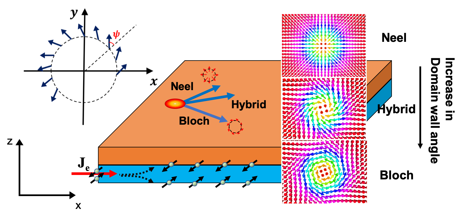
Dynamics of hybrid skyrmions. One way to move a skyrmion is to use a FM/HM structure. A current in the HM layer, say Pt, separates spins through a spin Hall effect, resulting in the injection of a perpendicular spin current into the FM that then diffuses away from the FM/HM interface. The injected spins precess incoherently around the FM magnetization, applying in the process a spin orbit torque that flips the background spins and drives the skyrmions Tomasello et al. (2015). The polarization direction of the spin current depends on the symmetry of the HM/FM stack. In our example, the polarization direction is , where is the current direction and is interface normal vector, assumed .
In a FM/HM structure (Fig. 1) the driving force from current induced SOT on a Néel skyrmion in the FM layer will be in the direction, and for a Bloch skyrmion in the - direction. The Magnus force for a Néel skyrmion will be in the direction and Bloch skyrmion in the direction. The net force from the SOT and Magnus effect generate perpendicular motion of Néel and Bloch skyrmions, with a hybrid skyrmion moving in between. We see this from the solution of the Thiele equation for the skyrmion velocity for a given domain angle Thiele (1973); Jiang et al. (2017)
| (1) |
where includes unaccounted forces like gradients of effective fields or skyrmion-skyrmion interactions, is the gyrotropic vector, is the skyrmion winding number, is the dissipation tensor (assumed isotropic with diagonals ), is Gilbert damping, is the SOT pre-factor, is the electron charge, reduced Planck’s constant, is the gyromagnetic ratio, is the FM thickness, saturation magnetization, , is the angle between magnetic moment and axis, is the size of the skyrmion core relative to the domain wall width . is the 2D rotation matrix involving the domain angle , is spin hall angle, and is the current density in the HM layer, assumed to be along the direction. Solving for :
| (2) |
where is the gyrotropic tensor. From this equation, we can extract the skyrmion hall angle , and the critical domain angle where the Magnus force vanishes (). At zero force , we get
| (3) | ||||
| (4) |
with .
The domain angle , set by the ratio of bulk to interfacial DMI, determines if a skyrmion is Néel (Figs. 2, 3) (), Bloch () or hybrid (. For a given and , the velocities of Bloch and Néel skyrmions are perpendicular to each other (), so that a proper hybrid skyrmion at domain angle moves along the current direction. However, reaching this domain wall angle requires a precise tuning of parameters.
Spatially varying iDMI for self-focusing skyrmions. Let us now consider a hybrid skyrmion moving in a FM layer with both bulk DMI (e.g. a B20 material like FeGe or MnSi) and a linearly varying interfacial DMI from HM spin-orbit coupling Liu et al. (2012)
| (5) |
The DMI energy density . Solving , we can then get the evolution of as a function of y from Eq 5
| (6) |
meaning the skyrmions pick up increasingly more Néel characteristic during transit. The corresponding force from the linearly varying interfacial DMI Díaz and Troncoso (2016):
| (7) |
Where . Using a 2 domain wall model for the azimuthal angle (distinct from domain wall angle ), , the DMI integral can be approximated as . Putting in in the Thiele equation, we get a correction to the critical angle: , with . As Fig. 2 shows, the convergent lane depends on the anisotropy parameter , which in turn affects the skyrmion size and thereby the dissipation tensor responsible for the critical domain angle . The dissipation integral is defined as Büttner et al. (2018):
| (8) | |||
in a 2 domain wall model. The integral above does not have an analytical solution to our knowledge. However, a simple fit that works quite well for is , so that:
| (9) |
The anisotropy dependence of the skyrmion size can be seen from an evaluation of the energy integrals within a model Rohart and Thiaville (2013); Xie et al. (2020), and can be approximated as (with zero external magnetic field)
| (10) |
where , , and is the total DMI. Since is changing with y (Eq. 5), is a function of y for a given anisotropy. Solving for y, we get the convergence lane (Fig 2).
We perform micromagnetic (MuMax3 Vansteenkiste et al. (2014)) simulations to verify our assumptions and see skyrmion behavior in a linearly varying iDMI with different anisotropies (Fig. 2).
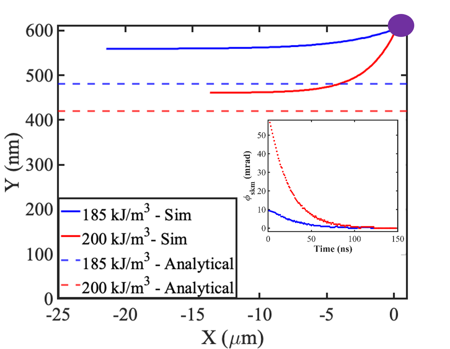
The parameters used in simulation are taken from Wu et al. (2017); Kim et al. (2018); Turgut et al. (2018); Dhital et al. (2017) for FeGe, kA/m, = 7.5e-12 , = 1 , , = 185, 200 kJ/m3 (assuming interfacial effects for ultra thin FeGe), and . The FM layer thickness is taken to be 2 nm. We apply a spin current of polarization in the direction, arising for instance from SOT in the HM layer from a charge current in the direction. The Magnus force will cause the skyrmion to have a velocity component in the direction. As the skyrmion comes down the FM, the interfacial DMI decreases, which leads to an increasing domain wall angle (Eq. 6), until it reaches the critical angle where it no longer has a velocity component along and will have a rectilinear motion, self-focusing into a lane in the process.
Fig. 2a shows the tracks for a skyrmion injected at the low iDMI end, as obtained from a numerical simulation of the Landau-Lifschitz-Gilbert equation (which goes beyond the rigid skyrmion Thiele approximation), for various bulk anisotropy values . The horizontal dashed lines show the convergent path coordinates obtained from analytical approximations ana . The decrease in skyrmion size along the travel path means that smaller skyrmions (e.g. with higher anisotropy) travel further down before self-focusing.
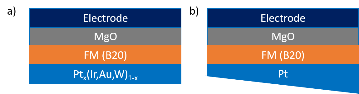
To get a linearly varying iDMI we suggest two possible approaches (Fig 3) - one is to use a varying thickness of HM layer, or more realistically of an MgO film between the HM layer and FM layer, to tune the iDMI. According to the experiments done in Tacchi et al. (2017); Cao et al. (2018), by putting a MgO layer between HM and FM, the iDMI can be increased substantially and this effect increases with thickness of MgO until it saturates for a thickness of around 2 nm. As the MgO layer has significantly higher resistance than the HM layer, most of current will travel trough the HM layer. However, further investigation is needed to understand how the separation between HM and FM layer due to the MgO layer alters the effective momentum transfer. A second approach is to use a non uniform composition of HM, e.g. Zhu et al. (2019); Lau and Sokalski (2019). It has been seen by using a composition of that the iDMI increases with increasing from 0 to 1. The main fabrication challenge is growing high quality B20 thin films on heavy metals and underlying the MgO.
VCMA for gate dependent lane selection.From Eq. 9, if we increase , would decrease. One way to increase is by reducing the anisotropy and thus (Eq. 10). We can gate control the skyrmion size through Voltage Controlled Magnetic Anisotropy (VCMA), in effect, voltage gating the Stark shift of the bond between the magnet’s orbital and the oxygen orbital of an oxide layer like MgO grown on the side of the sample opposite the HM layer (Fig. 3). The equation describing the perpendicular magnetic anisotropy variation with gate voltage in a VCMA set-up is
| (11) |
with the oxide thickness and the VCMA coefficient. This means with a gate voltage, we can change the anisotropy and , the size of the skyrmion, the dissipation tensor and ultimately the critical angle - making the skyrmion converge to a different lane. Assuming a thickness of 1 nm for oxide and FM layers, we would need a to get a change in anisotropy per 1V. of 50-100 fJ/Vm has been achieved for CoFeB of 1 nm thickness Kanai et al. (2012); Xue et al. (2019), whereas by doping FM/oxide interface larger than 100 fJ/Vm has been reported Rana and Otani (2019); Nozaki et al. (2019), suggesting that our device parameters are quite realizable for lane control. To get a higher separation of lanes, we can choose a smaller term in Eq 5. This can be done by making the doping variation slower in Fig. 3a, or using Pt with a slower thickness variation, Fig 3b.
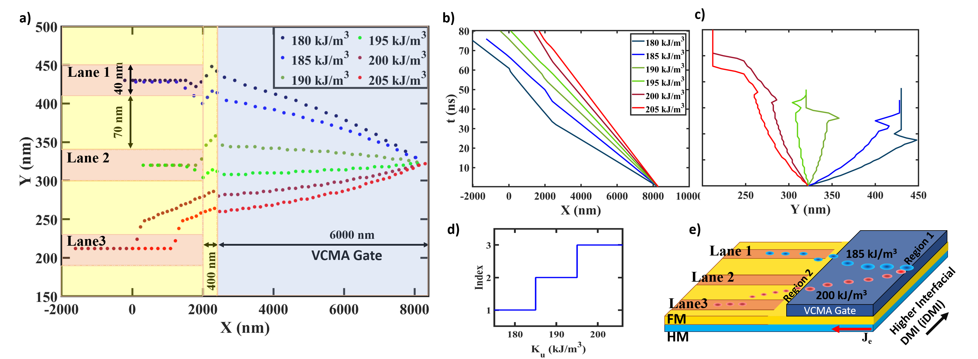
Fig. 4 shows how skyrmions can be made to self-focus into a set of prefabricated racetracks using a VCMA gate Zhang et al. (2018). Anisotropy in the fabricated lanes is , separated by regions with higher magnetic anisotropy . While the skyrmion domain angle evolves during transport along , the VCMA gate changes the local anisotropy and alters the bending of the skyrmion track, attempting to set them into alignment with the racetracks. The VCMA gate can change the anisotropy of the magnetic film under it, enough to bend the skyrmion path towards one of the lanes. The competition between attractive force from the lanes vs. Magnus force in region 2 determines which lane a
skyrmion will converge to. When the alignment is not perfect (non-resonant skyrmion), the skyrmions instead enter the region between the lanes. The lane locations and relative anisotropies are designed so the skyrmions entering the regions in between the tracks see a Magnus force in the direction, as well as an attractive force towards the nearest racetrack. The net force will determine which track the non-resonant skyrmions finally converge to. Once they enter a lane, the repulsive force from the interstitials cancels out the Magnus force and the skyrmions stay in lane. Since the interstitials have higher anisotropy, even skyrmions which miss the lanes eventually end up in one of the lanes whereupon their combined anisotropy repulsion and Magnus force vanishes again. As a result, we get a stepfunction-like quantized behaviour (Fig 4b) for the final coordinate of the convergent skyrmion lanes as a function of the VCMA engineered anisotropy, implying a robust well controlled scheme for directing skyrmions into the lanes. We emphasize that this ability to control lanes dynamically is unique to skyrmions with flexible domain angles, and is not achievable with domain walls.
To see thermal effects, we performed stochastic simulations at room temperature (supplementary, fig S1Sup ). Thermal effects cause fluctuation in the skyrmion’s coordinate, which may create uncertainties near the separatrix between trajectories going to neighboring lanes. The thermally limited transition, inherent in all devices, can be reduced with materials with higher exchange parameter, or a slower variation of iDMI, compared to the separation of lanes. As long as the lane separations are much larger than the position fluctuations, the system should operate reliably at room temperature. Overall, as in any other device, we need to design and optimize around such inherent instabilities.
Summary. In this paper we have shown a dynamic method of controlling the skyrmion movement. In the literature, other methods of achieving self convergence has been investigated Kim et al. (2017); Wu et al. (2017); Kim et al. (2018) but the self convergence is not dynamic or needs extra fine turnings. The advantage of our method is the ability to achieve multiple converging lanes. In addition we can dynamically control position of converging lanes and skyrmion movement. The self convergence would circumvent some of the extra fine tuning needed compared to other methods. By using a local VCMA gate, we showed an added degree of flexibility can be achieved which in turn can be used to dynamically manipulate the logic flow. The existence of multiple convergence lane makes it possible to do more complicated logic operations compared to the racetracksTomasello et al. (2015); Zhang et al. (2020); Luo et al. proposed in the literature. We have also provide a quasi analytical method to predict the convergence lane which matches reasonably well with the simulations results.
Acknowledgments. This work is funded by the DARPA Topological Excitations in Electronics (TEE) program (grant D18AP00009). We would like to thank Joseph Poon, Mircea Stan, Andy Kent, Prasanna Balachandran and Samiran Ganguly for insightful discussions.
References
- Bogdanov and Yablonskii (1989) AN Bogdanov and DA Yablonskii, “Thermodynamically stable” vortices” in magnetically ordered crystals. the mixed state of magnets,” Zh. Eksp. Teor. Fiz 95, 182 (1989).
- Bogdanov and Rößler (2001) A. N. Bogdanov and U. K. Rößler, “Chiral Symmetry Breaking in Magnetic Thin Films and Multilayers,” Physical Review Letters 87, 037203 (2001).
- (3) K. Everschor-Sitte, J. Masell, R. M. Reeve, and M. Kläui, “Perspective: Magnetic skyrmions—overview of recent progress in an active research field,” 124, 240901.
- (4) Giovanni Finocchio, Massimiliano Di Ventra, Kerem Y. Camsari, Karin Everschor-Sitte, Pedram Khalili Amiri, and Zhongming Zeng, “The promise of spintronics for unconventional computing,” 1910.07176 .
- Woo et al. (2016) Seonghoon Woo, Kai Litzius, Benjamin Krüger, Mi-Young Im, Lucas Caretta, Kornel Richter, Maxwell Mann, Andrea Krone, Robert M. Reeve, Markus Weigand, Parnika Agrawal, Ivan Lemesh, Mohamad-Assaad Mawass, Peter Fischer, Mathias Kläui, and Geoffrey S. D. Beach, “Observation of room-temperature magnetic skyrmions and their current-driven dynamics in ultrathin metallic ferromagnets,” Nature Materials 15, 501–506 (2016).
- Seki et al. (2012) S. Seki, X. Z. Yu, S. Ishiwata, and Y. Tokura, “Observation of Skyrmions in a Multiferroic Material,” Science 336, 198–201 (2012).
- Nagaosa and Tokura (2013) Naoto Nagaosa and Yoshinori Tokura, “Topological properties and dynamics of magnetic skyrmions,” Nature Nanotechnology 8, 899–911 (2013).
- Tomasello et al. (2018) R. Tomasello, S. Komineas, G. Siracusano, M. Carpentieri, and G. Finocchio, “Chiral skyrmions in an anisotropy gradient,” Phys. Rev. B 98, 024421 (2018).
- Fook et al. (2015) H. Fook, C. Ang Ching Ian, W. Gan, I. Purnama, and W. Lew, “Mitigation of magnus force in current-induced skyrmion dynamics,” 2015 IEEE Magnetics Conference (INTERMAG), , 1–1 (2015).
- Zhang et al. (2016) Xichao Zhang, Yan Zhou, and Motohiko Ezawa, “Magnetic bilayer-skyrmions without skyrmion Hall effect,” Nature Communications 7, 10293 (2016).
- Kim et al. (2017) Se Kwon Kim, Kyung-Jin Lee, and Yaroslav Tserkovnyak, “Self-focusing skyrmion racetracks in ferrimagnets,” Physical Review B 95, 140404 (2017).
- Kim et al. (2018) Kyoung-Whan Kim, Kyoung-Woong Moon, Nico Kerber, Jonas Nothhelfer, and Karin Everschor-Sitte, “Asymmetric skyrmion Hall effect in systems with a hybrid Dzyaloshinskii-Moriya interaction,” Physical Review B 97, 224427 (2018).
- Wu et al. (2017) H. Z. Wu, B. F. Miao, L. Sun, D. Wu, and H. F. Ding, “Hybrid magnetic skyrmion,” Physical Review B 95, 174416 (2017).
- Leonov and Mostovoy (2017) A. O. Leonov and M. Mostovoy, “Edge states and skyrmion dynamics in nanostripes of frustrated magnets,” Nature Communications 8, 14394 (2017).
- Díaz and Troncoso (2016) Sebastián A Díaz and Roberto E Troncoso, “Controlling skyrmion helicity via engineered Dzyaloshinskii–Moriya interactions,” Journal of Physics: Condensed Matter 28, 426005 (2016).
- Zhang et al. (2020) Haoyang Zhang, Daoqian Zhu, Wang Kang, Youguang Zhang, and Weisheng Zhao, “Stochastic computing implemented by skyrmionic logic devices,” Phys. Rev. Applied 13, 054049 (2020).
- Sakib et al. (2020) Mohammad Nazmus Sakib, Hamed Vakili, Samiran Ganguly, Sergiu Mosanu, Avik W. Ghosh, and Mircea Stan, “Magnetic skyrmion-based programmable hardware,” in Spintronics XIII, Vol. 11470, edited by Henri-Jean M. Drouhin, Jean-Eric Wegrowe, and Manijeh Razeghi, International Society for Optics and Photonics (SPIE, 2020) pp. 129 – 140.
- Rowland et al. (2016) James Rowland, Sumilan Banerjee, and Mohit Randeria, “Skyrmions in chiral magnets with Rashba and Dresselhaus spin-orbit coupling,” Physical Review B 93, 020404 (2016).
- Tomasello et al. (2015) R. Tomasello, E. Martinez, R. Zivieri, L. Torres, M. Carpentieri, and G. Finocchio, “A strategy for the design of skyrmion racetrack memories,” Scientific Reports 4, 6784 (2015).
- Thiele (1973) A. A. Thiele, “Steady-State Motion of Magnetic Domains,” Physical Review Letters 30, 230–233 (1973).
- Jiang et al. (2017) Wanjun Jiang, Xichao Zhang, Guoqiang Yu, Wei Zhang, Xiao Wang, M. Benjamin Jungfleisch, John E. Pearson, Xuemei Cheng, Olle Heinonen, Kang L. Wang, Yan Zhou, Axel Hoffmann, and Suzanne G. E. te Velthuis, “Direct observation of the skyrmion Hall effect,” Nature Physics 13, 162–169 (2017).
- Liu et al. (2012) Luqiao Liu, O. J. Lee, T. J. Gudmundsen, D. C. Ralph, and R. A. Buhrman, “Current-Induced Switching of Perpendicularly Magnetized Magnetic Layers Using Spin Torque from the Spin Hall Effect,” Physical Review Letters 109, 096602 (2012).
- Büttner et al. (2018) Felix Büttner, Ivan Lemesh, and Geoffrey S. D. Beach, “Theory of isolated magnetic skyrmions: From fundamentals to room temperature applications,” Scientific Reports 8, 4464 (2018).
- Rohart and Thiaville (2013) S. Rohart and A. Thiaville, “Skyrmion confinement in ultrathin film nanostructures in the presence of Dzyaloshinskii-Moriya interaction,” Physical Review B 88, 184422 (2013).
- Xie et al. (2020) Y. Xie, J. Ma, H. Vakilitaleghani, Y. Tan, and A. W. Ghosh, “Computational search for ultrasmall and fast skyrmions in the inverse heusler family,” IEEE Transactions on Magnetics 56, 1–8 (2020).
- Vansteenkiste et al. (2014) Arne Vansteenkiste, Jonathan Leliaert, Mykola Dvornik, Mathias Helsen, Felipe Garcia-Sanchez, and Bartel Van Waeyenberge, “The design and verification of MuMax3,” AIP Advances 4, 107133 (2014).
- Turgut et al. (2018) Emrah Turgut, Hanjong Paik, Kayla Nguyen, David A. Muller, Darrell G. Schlom, and Gregory D. Fuchs, “Engineering Dzyaloshinskii-Moriya interaction in B20 thin-film chiral magnets,” Physical Review Materials 2, 074404 (2018).
- Dhital et al. (2017) C. Dhital, L. DeBeer-Schmitt, Q. Zhang, W. Xie, D. P. Young, and J. F. DiTusa, “Exploring the origins of the Dzyaloshinskii-Moriya interaction in MnSi,” Physical Review B 96, 214425 (2017).
- (29) We are treating skyrmion as a point particle with zero dimensions. Since DMI is linearly varying this assumption will result in a small disagreement with LLG simulations. .
- Tacchi et al. (2017) S. Tacchi, R. E. Troncoso, M. Ahlberg, G. Gubbiotti, M. Madami, J. Åkerman, and P. Landeros, “Interfacial Dzyaloshinskii-Moriya Interaction in Pt / CoFeB Films: Effect of the Heavy-Metal Thickness,” Physical Review Letters 118, 147201 (2017).
- Cao et al. (2018) Anni Cao, Xueying Zhang, Bert Koopmans, Shouzhong Peng, Yu Zhang, Zilu Wang, Shaohua Yan, Hongxin Yang, and Weisheng Zhao, “Tuning the Dzyaloshinskii–Moriya interaction in Pt/Co/MgO heterostructures through the MgO thickness,” Nanoscale 10, 12062–12067 (2018).
- Zhu et al. (2019) Lijun Zhu, Kemal Sobotkiewich, Xin Ma, Xiaoqin Li, Daniel C. Ralph, and Robert A. Buhrman, “Strong Damping‐Like Spin‐Orbit Torque and Tunable Dzyaloshinskii–Moriya Interaction Generated by Low‐Resistivity Pd Pt Alloys,” Advanced Functional Materials 29, 1805822 (2019).
- Lau and Sokalski (2019) D. Lau and V. Sokalski, “The interfacial Dzyaloshinskii-Moriya interaction and spin-orbit torque driven domain wall motion in Co/Ni multi-layers with a Pt (Ir,Au) seedlayer,” AIP Advances 9, 035208 (2019).
- Kanai et al. (2012) S. Kanai, M. Yamanouchi, S. Ikeda, Y. Nakatani, F. Matsukura, and H. Ohno, “Electric field-induced magnetization reversal in a perpendicular-anisotropy cofeb-mgo magnetic tunnel junction,” Applied Physics Letters , 122403 (2012).
- Xue et al. (2019) Fen Xue, Noriyuki Sato, Chong Bi, Jun Hu, Jinliang He, and Shan X. Wang, “Large voltage control of magnetic anisotropy in CoFeB/MgO/OX structures at room temperature,” APL Materials 7, 101112 (2019).
- Rana and Otani (2019) Bivas Rana and YoshiChika Otani, “Towards magnonic devices based on voltage-controlled magnetic anisotropy,” Communications Physics 2, 90 (2019).
- Nozaki et al. (2019) Takayuki Nozaki, Tatsuya Yamamoto, Shinji Miwa, Masahito Tsujikawa, Masafumi Shirai, Shinji Yuasa, and Yoshishige Suzuki, “Recent Progress in the Voltage-Controlled Magnetic Anisotropy Effect and the Challenges Faced in Developing Voltage-Torque MRAM,” Micromachines 10, 327 (2019).
- Zhang et al. (2018) Bangmin Zhang, Lijun Wu, Jincheng Zheng, Ping Yang, Xiaojiang Yu, Jun Ding, Steve M. Heald, Richard A Rosenberg, Thirumalai Venky Venkatesan, Jingsheng Chen, Cheng-Jun Sun, Yimei Zhu, and Gan Moog Chow, “Control of magnetic anisotropy by orbital hybridization with charge transfer in (La0.67sr0.33mno3)n/(SrTiO3)n superlattice,” NPG Asia Materials 10, 931–942 (2018).
- (39) “See supplemental material at [url will be inserted by publisher] for room temperature simulations,” .
- (40) Shijiang Luo, Min Song, Xin Li, Yue Zhang, Jeongmin Hong, Xiaofei Yang, Xuecheng Zou, Nuo Xu, and Long You, “Reconfigurable skyrmion logic gates,” 18, 1180–1184.