Patterns and Interactions in Network Security††thanks: © Pamela Zave and Jennifer Rexford, 2019, 2020.
1 Introduction
Today’s Internet is not worthy of the trust society increasingly places in it. We hear every day about new security vulnerabilities and successful attacks, ranging from email viruses and Web sites overrun with unwanted traffic, to network outages, compromised user data, and downright espionage. These attacks are costly, leading to denial of service, loss of revenue, identity theft, ransom demands, subversion of the democratic process, malfunctioning safety-critical equipment, and more.
Many successful security attacks use “social engineering” to prey on naive users, for example by getting them to click on malicious hyperlinks. Users are often guilty of using easily-guessed passwords, or failing to reset a default password on a new device. Application software is also the source of many security vulnerabilities, due to bugs or poor programming practices. Its complexity provides a big “attack surface” for adversaries to probe for weaknesses.
Despite the prevalence of social engineering and vulnerable applications, networks are an important part of the security landscape. Networks make attacks on applications possible by delivering unwanted traffic or leaking sensitive data. Network components and network services are often the targets of attacks. Sometimes a network itself is the adversary, performing unethical surveillance or censoring communication.
Fortunately, networks can also be part of the solution, by blocking unwanted traffic, enabling anonymous communication, circumventing censorship, or protecting both infrastructure and applications from a range of known attacks. And network protocols can protect users by authenticating and encrypting communications.
This article is intended as a concise tutorial on the very large subject of security by and for networks, specifically the mechanisms through which network security is achieved. It is intended to be useful to all readers interested in networks, whether their specialty is security or not. Because the basic mechanisms have proven to be fairly stable over time, we do not emphasize which particular attacks and defenses are trending at the moment. The details of well-motivated attacks or cost-effective defenses change as technology changes, and particular defenses might cycle in and out of fashion. Instead, to achieve the goal of the paper, we derive our focus and organization from two perspectives.
The first perspective is that, although mechanisms for network security are extremely diverse, they are all instances of just a few patterns. By emphasizing the patterns, we are able to cover more ground. We also aim to help the reader understand the big issues and retain the most important facts.
The second perspective comes from the observation that security mechanisms interact in important ways, with each other and with other aspects of networking. Although these interactions are not frequently discussed, they deserve our attention. To provide communication services that are secure and also fully supportive of distributed applications, network designers must understand the consequences of their decisions on all aspects of network architecture and services.
The boundaries of network security have been drawn by convention over time, so §2 begins the tutorial by defining network security in two ways. First, there is a practical classification of network security attacks, based primarily on which agents are the attackers, defenders, and potential victims. The classification is based secondarily on defense mechanisms. Second, we discuss how network security is related to information security and other forms of cyber-security, as well as the gaps where no comprehensive defenses yet exist.
The four main sections of the tutorial cover the four major patterns for providing network security. All agents can protect their own communications with cryptographic protocols (§4), which (among other benefits) hide the data contents of packets. Networks can protect both themselves and their users by traffic filtering (§5). Both users and networks can employ dynamic resource allocation to overcome attacks (§6). Although cryptographic protocols hide the data contents of packets, they cannot hide packet headers, because the network needs them to deliver the packets. So when users need to hide packet headers from adversaries, which may include the network from which they are receiving service, they must resort to compound sessions and overlays (§7). The first three patterns will be familiar to anyone who has even dabbled in network security, while the importance of the fourth pattern has not been sufficiently recognized.
Between the definition of network security and the four major sections, §3 presents a new descriptive model of networks and network services. This model explains how network services are provided by means of composition of many networks at many levels of abstraction, where each network is self-contained in the sense of having—at least potentially—all the basic mechanisms of networking (such as routing, forwarding, session protocols, and directories). This model allows complete and precise descriptions of today’s network architectures. It is also necessary for recognition of the four patterns, because the same patterns are reused in different networks in a compositional architecture. The patterns are reusable precisely because the different networks have fundamental similarities, despite the fact that they may have different purposes, levels of abstraction, membership scope, or geographical span.
In each of the four main sections, in addition to presenting a security mechanism, we consider how the mechanism interacts with other mechanisms within its network and across composed networks. This helps to determine where security could and should be placed in a compositional network architecture.
2 What is network security?
Network security is a pragmatic subject with boundaries that have been drawn by convention over time. Although the focus of this tutorial is defense mechanisms, we must have some idea of what kind of attacks they can defend against.
Classifying security attacks is extremely difficult because—by their very nature—security attacks are clever, they exploit gaps in standard models, and they are always evolving. In §2.1 we present a practical classification scheme based on multiple factors. It only covers known attacks, and there are some overlaps in the categories, but it does provide intuition that will be helpful for understanding the defenses.
Of all the factors relevant to security attacks, the worst factor for purposes of classification is real-world consequences (or, alternatively, the motivations of attackers). These consequences include financial loss, loss of time, loss of privacy, loss of reputation, loss of political freedom, loss of physical safety, and so on. Often, these losses are intertwined, because one loss causes another. Some attacks have no direct real-world consequences: their sole purpose is to enable other, more damaging, attacks.
Our practical classification scheme, summarized in Figure 1, is based primarily on which agents are the attackers, defenders, and potential victims. With one exception (see table), agents can be either:
-
•
the network, meaning the infrastructure machines provided by the network operator to run the network,
-
•
safe users, meaning machines that use a network for communication and whose behavior is satisfactory according to whatever rules or authorities apply, or
-
•
unsafe users, meaning machines that have access to a network and whose behavior is unsatisfactory because they have been programmed maliciously, ignorantly, or erroneously.
Classification is based secondarily on defense mechanisms; these must be secondary to defenders because some mechanisms are only available to some defenders.
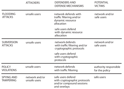
Note that the network is usually a defender, but can be an attacker. Even though traffic filtering is a possible defense for three attack categories, as we will explain below, the details of filtering against different attacks are quite different.
In §2.2 we will discuss alternative definitions of security. These include other kinds of cyber-security that complement network security, attacks for which comprehensive defenses do not yet exist, and alternative classification schemes.
2.1 A practical classification of network security attacks
2.1.1 Flooding attacks
In a flooding attack, attackers send floods of packets toward the victim, seeking to make it unavailable by exhausting its resources. Consequently, flooding attacks are one type of denial-of-service attack (see §2.2.1).
The intended victims of flooding attacks vary. If the victim is a public server or user machine, the attack might seek to exhaust its compute-cycle, memory, or bandwidth resources. Note that some public servers such as DNS servers are part of the infrastructure of a network, so a flooding attack on a DNS server is an attempt to deny some network services to a large number of users. An attacker might also target some portion of a network, seeking to exhaust the bandwidth of its links. A bandwidth attack can make particular users unreachable, and can also deny network service to many other users whose packets pass through the congested portion of the network. A bandwidth attack can also shift traffic to a less-secure part of a network, enabling other security attacks.
If an attacker simply sends as many packets as it can toward a victim, the resources expended by the attacker may be similar to the resources expended by the victim! A distributed denial-of-service attack can be launched from many coordinated machines, focusing the resources of many machines onto a smaller number of targets. Alternatively, a flooding attack can employ some form of amplification, in which the attacker’s resources are amplified to cause the victim to expend far more resources. Here are some well-known forms of amplification:
-
•
A “botnet” is formed by penetrating large numbers (as in millions) of innocent-but-buggy machines connected to the Internet, and installing in them a particular kind of malware. Subsequently the attacker sends a triggering packet to each member of the botnet, causing it to launch a security attack unbeknownst to the machine’s owner. This is another kind of distributed denial-of-service attack.
-
•
An “asymmetric attack” sends requests to a server that require it to expend significant compute or storage resources for each request, so that a relatively small amount of traffic is sufficient to launch a significant attack. A typical IP example is a “SYN flood,” in which the victim receives a flood of TCP SYN (session initiation) packets. Each packet causes the server to do significant work and allocate significant resources such as buffer space. Also in IP networks, attackers can flood DNS servers with queries for random domain names (a “random subdomain attack”). These will force the servers to make many more queries, because they will have no cached results to match them. In a Web-based application network, the attacker can send particular HTTP requests that force a Web server to do a large amount of computation.
-
•
An attacker can send many request packets to public servers, with the intended victim’s name as source name. This “reflection attack” causes all the servers to send their responses to the victim. It amplifies work because responses (received by the victim) are typically much longer than requests (sent by the attacker).
-
•
In an Ethernet network, a forwarder’s response to receiving a packet to an unknown destination is to “flood” the network with it, which means (in this case) to send it out all links so that eventually all machines receive it and the designated destination responds to it. An attacker can amplify any packet this way, simply by putting in an unused destination name.
Network infrastructure provides the principal defense against flooding attacks, by filtering out attack packets (§5). Flooding attacks can also be countered by allocating additional resources to handle peak loads (§6); this is something that both network infrastructure and targeted users can do.
If network infrastructure discovers where attack traffic is coming from, defending against the attack becomes much easier. For this reason, attackers employ various techniques to hide themselves, for example:
-
•
In an IP network, a sender can simply put a false source name in the packet header, commonly called “spoofing.” In email applications, source email addresses are also easily spoofed.
-
•
With a botnet, even if bots use their true source names, there may be too many of them to cut off. The IP address of the master of the botnet remains hidden.
-
•
An attacker can hide by putting a smaller-than-usual number in IP packets’ time-to-live fields, so that the packets are dropped after they have done their damage in congesting the network, but before they reach a place where measurements are collected or defenses are deployed.
Flooding attacks are a very serious problem in today’s Internet. There are businesses that generate them for small fees. They target popular Web sites and (especially) DNS [17]. The worst attacks are mounted by enterprises, albeit illegal ones, that can draw on the same kind of professional knowledge, human resources, and computer resources that legitimate businesses and governments have. Such attackers will use many attacks and combinations of attacks at once, and can continue them over a long period of time. According to industry reports, we are entering the era of flooding attacks of terabits per second [3].
2.1.2 Subversion attacks
The purpose of a subversion attack on a network member is to get the victim’s machine to act as the attacker wants it to, rather than as the owner of the machine wants. Here are some well-known examples of subversion attacks:
-
•
The attacker sends malware to infect or penetrate the machine. The malware might be spyware or ransomware, capable of stealing or damaging data stored in the machine. The malware might turn the machine into a bot, so the botnet master can exploit the machine’s resources. Or it might attack the physical world through devices controlled by the machine.
-
•
Port scanning is the process of trying TCP and UDP destination ports on a range of IP addresses, to find pairs that will accept a session initiation. Port scanning does not in itself do much harm, but it is gathering information to be used in launching other malware attacks. This is because most malware targets a known vulnerability in a specific application program. Scanning is less productive in IPv6, because the address space is much larger, but specially focused scans may still succeed.
-
•
The Border Gateway Protocol (BGP) is a control protocol through which IP networks exchange routing information. In “BGP hijacking,” an attacker uses BGP to insert false information, telling routers to send packets with certain destination names to the attacker rather than the true destination. The attacker may simply drop the redirected packets, denying service to the victim. The attacker can also respond to the packets as an impersonation of the intended destination, for the purpose of stealing commerce or secrets.
-
•
Subversion attacks on directories also insert false information. Higher-level names will then be mapped to the wrong lower-level names, with the same consequences as route hijacking. The directory protocol DNS (World-Wide Web name to IP address) and the IPv4 directory protocol ARP (IP address to Ethernet address) are subject to subversion attacks, as is the IPv6 replacement for ARP, called Neighbor Discovery.
-
•
Email spam and voice-over-IP robocalls can be considered subversion attacks. A networked device’s owner wants the device for communicating with acquaintances and chosen institutions. These attacks force the device to present ads and other unsolicited junk to the attention of its owner.
If a receiver of information knows the correct source of that information, then both users and network components can protect themselves from subversion by using cryptographic protocols. With cryptographic authentication, they know the identity of the agent with which they are communicating.
In other cases, network infrastructure protects itself and its users from subversion attacks by traffic filtering. But filtering for subversion attacks is significantly different from filtering for flooding attacks because subversion requires two-way communication between attacker and victim. For example, if the victim is a server that communicates using TCP, the attacker cannot send data to it until the initial TCP handshake is completed. This means that an attacker cannot hide by spoofing: if an attacker puts a false source name in its first packet to the victim, it will never receive a reply to its SYN, and can never complete the handshake.
2.1.3 Policy violations
Obviously, the default behavior of a network is to provide all communication services requested of it. These services should be provided according to explicit or implicit agreements about quality and privacy.
On the other hand, the administrative authority of the network, or other authorities such as governments, employers, and parents, may have policies constraining network communication. Specific communications that violate these policies are security attacks, and the network defends against these attacks by tampering with the communications (up to and including blocking them) or by spying on them so that other enforcement actions become possible. These defenses are exceptions to the default behavior of the network. Examples of policy violations include:
-
•
Two users can communicate for the purpose of committing a crime. This should be prevented, or in some cases recorded for evidence in legal proceedings (“lawful intercept”). Similarly, the communications of suspected individuals can be monitored for surveillance and investigation.
-
•
Saboteurs can attempt to access the control system of a power grid.
-
•
A minor can attempt to access a Web site that violates parental controls.
-
•
A network may consider certain voice or video applications to take up more bandwidth than individual users are entitled to, and rate-limit them to minimize their effects on overall performance.
-
•
Operators of enterprise networks know which employees are using which machines for which purposes. Often they configure their networks to prevent unnecessary communications, which may be attacks, and can be blocked without harm even if they are only mistakes. For example, machines used by engineers should not have access to the enterprise’s personnel database.
Network infrastructure defends against policy violations by traffic filtering. As indicated above, violating packets can simply be discarded, but they can also be recorded, tampered with, or rate-limited.
Traffic filtering for policy enforcement is different from traffic filtering against flooding and subversion attacks because the filtering is so specific. There is often a specified target whose communications are being monitored. Flooding and subversion attacks, in contrast, usually have unknown sources, and their victims are often opportunistic.
2.1.4 Spying and tampering
The victims of spying and tampering are network users, who want their communications to be private, and want the network to be a transparent and effective medium of communication. The attackers in spying and tampering can be unsafe users, or they can also be the infrastructure machines of the network itself. Note that tampering is different from subversion because, in subversion, one endpoint of the communication is the attacker. In a tampering attack, the communication has two innocent endpoints, and the attacker is causing what one endpoint receives to differ from what the other endpoint sent.
When the attacker is the network, a spying or tampering attack is the exact dual of a policy violation—both the users and the network are doing exactly the same thing, and the only difference is which party we consider good or bad. Judgments of which behaviors are good or bad emerge from social debates involving legal, commercial, political, and ethical considerations. These debates should not be constrained by technology. Rather, the goal of technical experts should be to have the knowledge to implement whatever decisions emerge from these debates [15].
Examples of spying and tampering include:
-
•
Some governments censor the Internet usage of their citizens. Even if networks in their countries are privately owned, the governments can insist that network providers enforce their policies.
-
•
Some governments use surveillance of network usage as a tool in repression of or retaliation against political dissidents.
-
•
By observing the searches and Web accesses of a network user, an attacker can learn a great deal about the user’s personal life.
-
•
Network infrastructure can insert into the paths of user sessions middleboxes that insert ads or alter search results.
The “Great Cannon” is an example of a tampering attack that does no direct harm (to the endpoints of a targeted communication), but instead enables another attack. The attacker is a network, as the Great Cannon appears to share many resources with the Great Firewall of China. The Cannon replaces ads being fetched from Chinese servers (by machines outside China) with scripts that cause the recipients to access the servers of designated victims. At high volumes, this results in a distributed denial-of-service attack on the victims [39].
Network users have two possible defenses against spying and tampering. The first is the use of cryptographic protocols (§4), which conceal the data in transmitted packets. The second is the use of compound sessions and overlays (§7), which seek to hide packets so that even their headers, sizes, and timing cannot be observed.
2.2 Relation to other definitions of security
2.2.1 The information-security triad
Governments, enterprises, and other institutions have broad concerns about information security. These concerns are articulated by the well-known “information-security (CIA) triad,” consisting of the properties of confidentiality (secrecy, privacy, access control), integrity (the information is valid or uncorrupted or has correct provenance information), and availability (information can be read or written whenever needed).
These broad concerns about privacy include insider attacks and theft of physical storage media. The broad concerns about integrity and availability include natural disasters and even military attacks that might affect data centers. If the opposite of availability is denial-of-service, we can see that denial-of-service attack is also an extremely broad category.
Although the goals of the CIA triad have a great deal of overlap with the goals of network security, the classification scheme of §2.1 is far more focused. It is confined to threats incurred by operating a network or being connected to one, and it is closely tied to specific defense mechanisms within networks.
2.2.2 Complementary forms of security
For network users, network security is a first line of defense against subversion attacks; a major goal is to keep subversion packets from being delivered to user machines. If the packets do arrive, then security measures in operating systems and applications must take over. Many applications and most operating systems now have well-developed security measures of their own. However, old operating systems, real-time operating systems, and Internet of Things devices (which are highly resource-constrained) tend to have far fewer security mechanisms built in. For these endpoints, network defenses against subversion remain important.
Another subfield of security research and practice concerns “trust management,” which is technology aimed at deciding which agents should have permission to access which resources or perform which operations, based on the credentials and attributes of the agent, and on the permission policies applicable to the object (see, for example, [21, 35]). Trust management is a decision-making component of most forms of security, including network security. Distributed trust-management systems also rely on network security, for instance to communicate secret information safely among nodes of the system.
Most security experts would probably agree that the human side of security is the most important and the hardest to deal with. In an ideal world, all institutions would have sophisticated cyber-security policies, and enforce them. These policies would prevent (among other problems) insider attacks in which employees with access to code deliberately put bugs or backdoors in it. All people using computers would keep their software updated, choose hard-to-guess passwords, and change default passwords immediately. (Botnets are heavily populated with Internet of Things devices such as baby monitors, because they come with factory-installed passwords, and their naive owners do not change them.) No one would be fooled by “phishing” attacks, which imitate a legitimate email so that the recipient clicks on a malicious hyperlink embedded in it. And on and on.
2.2.3 Threats with inadequate defenses
Personal data privacy is a form of security that is much discussed in today’s world. Individuals are concerned about the massive amounts of personal data that is collected about them by Web sites, search engines, and other applications. This data is extremely valuable for selling advertising, and can also be used for worse purposes. Individual users can protect their privacy to some extent by using anti-spying defenses to achieve anonymity. Anonymously, they can email and participate in social media. At some point, however, full participation in electronic commerce and institutional services almost forces people to disclose their identities [54].
Finally, there is the growing threat of side-channel attacks. Network infrastructure monitors traffic to filter out flooding attacks, subversion attacks, and policy violations. Attackers also observe and analyze network traffic, for the purpose of spying and tampering. What are the characteristics of network traffic to be observed and analyzed, in addition to principal header fields and packet contents (which are explicitly intended and known to carry information)?
The timing and sizes of packets can be observed. Pseudo-random header fields, intended merely to group or distinguish packets, might be carrying secret codes. Optional header fields might reveal the configuration of the machine or software version that produced it. If the observer has access to the machine that sent the packet, it might be able to observe processor timing, power consumption, or usage of shared resources as the packet is prepared. Such access is possible if the machine is a stolen mobile device, or if multiple tenants share a physical machine in a cloud.
All of these characteristics are usually incidental, but they can be controlled by the sender to signal information to a knowledgeable observer that is invisible to other observers. This is known as a “covert channel.” Incidental characteristics can also be analyzed by an adversarial observer, to gain information despite the intentions of the sender. This is known as “side-channel” information [53]. Extracting side-channel information from packet timing and sizes is becoming more common, both for (good) filtering and (bad) spying, because the expanding use of cryptography has hidden much explicit information [42]. At present defenses against side-channel spying are patchy and experimental.
3 A model of networking
To find the patterns underlying network security mechanisms, and to understand how these patterns interact with each other and with other aspects of network architecture, we must be able to describe today’s networks in a way that is somewhat abstract and yet very precise. The “classic” Internet architecture [13] and the OSI reference model [27] have not kept up with the Internet’s evolution since the early 1990s. For a better way to describe networks, we will use the compositional model of networking introduced in [58].
In this section we give a brief overview of the compositional model, covering the structures and aspects that will be used in the rest of the tutorial. Although the model uses familiar terms, be aware that when they have definitions within the model, it is these precise and specific definitions that apply.
3.1 Components of a network
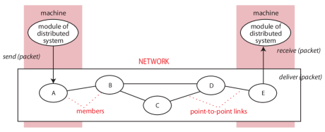
The components of a network are members and links. A member of a network is a software and/or hardware module running on a computing machine, and participating in the network. As a participant, the member implements some subset of the network’s protocols. A network member usually has a unique name in the namespace of the network. For example, Figure 2 shows five members of a network with unique names A, B, etc.
In the compositional model a network always has a single administrative authority, or alternatively network operator, which is a person or organization responsible for the network. The operator provides and administers resources for the network, in the form of links, members, and additional resources on the members’ machines. The operator is expected to protect the network’s resources and ensure that users of the network enjoy the promised communication services. It is convenient to partition the members of a network into infrastructure members administered by the operator to provide services, and user members belonging to the network for the purpose of employing its services.111In the case of peer-to-peer networks, each member contributes only its own resources, and there may be no central operator or administrator. For these networks, the authority is the cooperative agreement among members.
A network member can send or receive digital units called packets on one or more links of the network. A link is a communication channel. Most physical links are wires, optical fibers, or radio frequencies. Wires and optical fibers are usually used as point-to-point links, with two endpoints and transmission in one or both directions. Radio frequencies are broadcast links, on which any member with suitable hardware and within radio range can send or receive. In wired networks, buses (used in older Ethernets and cable networks) are also broadcast links, so packets can be sent and received by any machine connected to them.
Broadcast links are mostly ignored in this tutorial. The reason is that most links are virtual rather than physical (see §3.3), and the layering mechanism that creates virtual links is usually applied to make broadcast physical links appear as point-to-point virtual links in higher layers of a network architecture.
A public network allows any machine to host a network member and connect to the network, while a private network allows only authorized members. One of the two common authorization mechanisms is cryptographic protocols (§4). The other authorization mechanism is physical security, in which intruders are denied physical access to the links of the network.
3.2 Functions of a network
As shown in Figure 2, a network enables modules of a distributed system on different machines to communicate. We say that a network provides one or more communication services. A particular instance or usage of a communication service is called a session. Like a link, a session is also a communication channel for digital packets. The minimum semantics of a session is that it is a group of packets that the users of the service regard as belonging together.
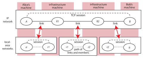
Communication services can be specified to have a wide variety of properties, which the network operator is obligated to enforce. There are two major mechanisms in networks for satisfying service specifications. The first is routing and forwarding. Forwarding is the mechanism that extends the reach of the network beyond individual links to paths of links; in forwarding, a member receives a packet on an incoming link, and sends it out on an outgoing link to get it closer to its destination. A forwarder is an infrastructure member whose primary purpose is forwarding. Figure 3 shows a path through an IP network between user members on Alice’s machine and on Bob’s machine. In the figure, R1 and R2 are “IP routers,” i.e., forwarders. All these names are “IP addresses.”
Routing is the control mechanism that controls forwarding by populating forwarding tables in forwarders. Forwarders consult their tables to know where to forward packets. Routing and forwarding can be extended beyond minimum requirements of reachability to perform services such as broadcasting and steering packets through middleboxes—members that perform various packet-processing functions related to security, efficiency, or interoperability.
Routing and forwarding work together by means of a network’s forwarding protocol, which is a set of rules governing the format of packets transmitted through the network. Each packet has a header part and a payload or data part. A header usually includes a source name indicating which member originally sent the packet, and a destination name indicating which member is intended to ultimately receive the packet. Entries in a forwarding table match fields in a packet header.
The other major mechanism for satisfying service specifications is session protocols. A session protocol is a set of rules governing packet formats, higher-level semantic units, and participant behavior during a session. In Figure 3, the session shown in the IP network uses the TCP session protocol. Following the rules of TCP, the session endpoints maintain state and send extra packets to provide reliable, ordered data delivery despite the facts that IP links are not perfectly reliable, and different packets of a session may be routed on different paths. UDP (another IP session protocol) is much simpler and implements fewer services, but it does define port numbers that can be used to group related packets.
3.3 Composition of networks
We have defined networks as self-contained modules with members, links, routing, forwarding, and session protocols. In today’s Internet, there are many networks, each of which may be specialized according to its purpose, membership scope, geographical span, and level of abstraction. A network architecture is a flexible composition of these networks, and thus called a “compositional network architecture” [58].
There are two composition operators on networks, the first being layering. The model defines layering precisely: one network is layered on another network if a link in the overlay network is implemented by a session in the underlay network. For example, each IP link in Figure 3 is implemented by a session in a local-area network, as indicated by the bold arrows. Members of different networks on the same machine communicate through the operating system and/or hardware of the machine. IP packets sent on an IP link are actually encapsulated in Ethernet headers and transported through local-area networks as the data parts of Ethernet packets. Since the implementation of an overlay link always consists of digital logic, whether in hardware or software, an overlay link is always virtual, regardless of whether the links in the underlay are physical or virtual. Note that the IP network in Figure 3 plays the same role as the distributed system in Figure 2.
As Figure 3 shows, almost all networked machines host members of at least two networks, and some host many more. We use the term member rather than node because the latter is too similar in connotation to machine. The figure shows how layering extends the reach of the local-area networks, each of which is isolated. A local-area network only implements an IP link, but the IP network can reach machines over paths that are concatenations of links.
The second composition operator on networks is bridging. Bridging simply means that two particular networks share some links, so they can forward packets to each other. If the designs of bridged networks are sufficiently homogeneous, in particular if they share session protocols, then sessions can cross network boundaries. In the Internet, many IP networks are bridged together in this way. These networks differ in their operators/administrative authorities, but not their basic design.
The definition of layering in compositional network architecture is very different from the older notion of layering in networks found in the “classic” Internet architecture [13] and OSI reference model [27]. In the new model, each layer is a complete network, so IP routing/forwarding and IP session protocols belong to the same network/layer. In the new model, an architecture has as many layers as needed, which often includes multiple IP networks layered on top of one another. We use the compositional model in this tutorial because it allows comprehensive yet precise descriptions of how the Internet actually works today [58]. It is also necessary for recognition of the four patterns, because the same patterns are reused in different networks in a compositional architecture. And layering of networks over networks and bridged sets of networks is especially important because it makes it possible to reason rigorously about networks from the bottom up: properties proved of an implementing session are automatically true of the implemented link.
3.4 Other forms of composition
Network composition is the most important form of composition in network architecture. Nevertheless, two other forms of composition, both found inside individual networks, are relevant to security.
3.4.1 Protocol composition
Control packets are used by a protocol to synchronize the endpoints and share specific parameters. Data packets contain the substance being communicated. Although a session protocol may have only one of these packet types, many protocols have both, or mix control information and data in a single packet.
Within a network, session protocols can be composed, so that the same session benefits from the services implemented by multiple protocols. When two session protocols and are composed, one of them is embedded in the other. If is embedded in , for instance, most packets in the session will have the format shown in Figure 4, in which the header and data are encapsulated in data (the figure also shows optional footers, which are required by some protocols). In addition, the session may include control packets of that are independent of and have no encapsulated packets.
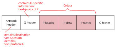
The figure shows an ideal packet format in which the network header of a packet includes the destination name and session identifier for the entire session, so that all packets of the session will be easily identifiable to the forwarders. Each network or protocol header names the type of the next header, if any, so that session protocols can be composed freely. Unfortunately, not all packet formats are so cleanly designed.
3.4.2 Compound sessions
A user member initiating a session to some far endpoint can insert another user member into the session path as a middlebox. To do this, the initiating user must give the name of the middlebox as the destination name of its outgoing packets, as shown in Figure 5. The middlebox must learn the initiator’s intended far endpoint, for example by getting it from some other field of the session-initiation packet. Then the middlebox changes the headers of the packets it receives (source becomes its own name, destination becomes the initiator’s intended) and sends them out. A middlebox that behaves in this way is called a proxy. Each proxy accepts a session, initiates another session with a different header, remembers the association between the two sessions, and relays packets between them. A compound session is a chain of simple sessions composed by proxies in this way.
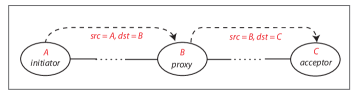
A compound session can have more than one proxy (as an example of how to do this, the session-initiation packet can contain a list of proxies to visit, ending with the final destination). Because of the names in forward packet headers, return packets naturally pass through the same proxies in reverse order, and have their headers re-translated in reverse order.
The principal security significance of compound sessions is that each simple session has a different header, so compound sessions can be employed by users to obscure header information (making them complementary to cryptography). In Figure 5, an observer between and cannot observe the true acceptor of the compound session, at least from packet headers alone, and an observer between and cannot observe the true initiator of the compound session.
4 Cryptographic protocols
Cryptographic protocols are incorporated into the session protocols of a network. Cryptographic protocols are executed by the endpoints of a point-to-point session, so that the session will have (data) integrity and (data) confidentiality. These are the same terms used in the information-security triad, but in this context they have a much more specific meaning. Confidentiality means that no party except a designated receiver can read the packets sent. Integrity means that no third party can insert, modify, or replay packets of the session, so that the packets received by a designated receiver are the exact packets sent by the designated sender, and if the sender sends a distinguished packet times, the receiver receives it at most times.
Cryptographic protocols can also achieve endpoint authentication, which means that either session endpoint can be sure of the other endpoint’s identity. Confidentiality should be reinforced by the property of forward secrecy, which means that even if an encrypted session is recorded by an attacker, and the attacker learns the secrets of one of its endpoints at some later time, the attacker still cannot decrypt and read the recorded packets.
User members of a network use cryptographic protocols to protect themselves against spying and tampering attacks. Infrastructure members, also, defend network operations against spying and tampering with cryptographic protocols.
It is important that cryptographic protocols are designed for the most hostile environments. For example, in accepted proof systems (such as [10, 40]), the baseline model of a security protocol allows an adversary to control all communication channels between the endpoints (and other agents they might query), examining, storing, deleting, injecting, or altering any packets that the adversary wishes. Because cryptographic protocols are designed (and proved mathematically) with such conservative assumptions, users trust them even when they can trust nothing about the layers of networking between endpoints.
§4.1 begins our discussion of cryptographic protocols by introducing the central concept of identity. The foundation for all cryptographic protocols is public-key cryptography (§4.2), because it provides some crucial functions and supports others. In §4.3 we return to the properties of data integrity and confidentiality. Finally, in §4.4 we discuss architectural interactions with cryptographic protocols that are relatively independent of other security patterns.
In §4.1 through §4.3 the context will be a single network of any kind. The discussion also covers a set of similar bridged networks all at the same level of the layering hierarchy, for example the bridged IP networks of the Internet. §4.4 broadens the context, as it includes how cryptographic protocols interact with composition of networks by layering.
4.1 Trust and identity
Security requirements are based on which network members do and do not “trust” each other. Of course a network member is a software or hardware module; it cannot trust in any ordinary sense of the word, and has no legal responsibility that it can be trusted to fulfill. For the purpose of establishing trust, a network member that is an endpoint of a session has an identity. This identity is given to the other endpoint of the session in answer to the question, “With whom am I communicating?”
This role implies that an identity should have meaning in the world outside the network. Often it is closely associated with a legal person—a person or organization—who is legally responsible for the network member. The identity is usually the source of the data that the network member sends during the session.
Identities are related to layering, because layering allows a machine to have different names—one in the namespace of each network it participates in—at the same time. For example, in Figure 6, each machine is participating in a higher-level Web-based application network and a lower-level IP network bridged with other IP networks. The dynamic sessions and links in the figure are formed as follows. The client’s browser at the upper level instructs its IP member to contact bigbank.com. When there is layering of networks, a directory is often used to find where an overlay member is attached to an underlay network. looks up bigbank.com in the DNS directory, and finds it is located on the same machine as IP member . At the lower level, initiates a TCP session to . When the TCP session (and dynamic link) are ready, the browser initiates a request/response HTTP session over it.
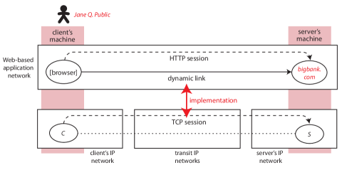
If the two endpoints of the TCP session need to authenticate each other (as they should, for a banking transaction), what identities do they give as their own? The general answer is that each gives its member name or the name of a higher-level network member that is using it. Either IP interface could give its IP name, but it would not be a very good identifier—too transient, or with too little meaning in the outside world. Instead, the server’s IP interface will be known by its public Web name bigbank.com. The client’s machine does not have a name in the application network, because the browser only initiates sessions and never accepts them. However, the user of the browser is a person named Jane Q. Public, whose clicks and keystrokes provide input to the browser. The browser will send Jane Q. Public as its identity, and we can imagine this identity as a member of an even-higher-level distributed financial system.
For endpoint authentication, a member must have access to a secret associated with the identity it provides. One kind of secret, useful when the two endpoints have an ongoing relationship, is a password. The server bigbank.com knows Jane’s password, and she can type it into the browser when requested.
For the important cryptographic protocols, however, the secret is always a public/private cryptographic key pair (see next section). The relationships among the important entities are shown in Figure 7. The identity is responsible for the packets sent by the network member, and the network member has access to the public key and its paired private key.
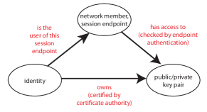
A “certificate authority” is trusted to ascertain that a particular public key belongs to a particular identity; it issues a certificate to that effect and signs it digitally. Thus when an endpoint receives a certificate, it can trust the identity that goes with the key (at least, as well as it trusts the certificate authority). As indicated above, identities found in certificates include names of legal persons, domain names, and IP addresses.
It should be noted that trust between communicating endpoints is not necessarily simple or absolute. For instance, two endpoints may be communicating to negotiate a contract, and (because they do not trust each other completely) need to communicate through a third party trusted by both. A trusted broker can ensure, for example, that both parties sign the exact same contract [9].
4.2 Public-key cryptography and its uses
In public-key cryptography, an identity generates and owns a coordinated pair of keys, one public and one kept private and secret. The important properties of these keys are that (i) it is extremely difficult to compute the private key from the public key, and (ii) plaintext encrypted with the public key can be decrypted with the private key, and vice-versa. Today’s public-key cryptography is descended from the Diffie-Hellman Key Exchange protocol and the RSA algorithm (named for its inventors Ron Rivest, Adi Shamir, and Leonard Adleman).
At present a key must be at least 2048 bits to be considered secure (the minimum size is expected to increase in the future). A public key is a pair of unsigned integers . The corresponding private key is a pair . To be encrypted, a packet must be divided into chunks such that each chunk has an integer representation less than . If is such a chunk, then the public-key encryption of is , and the private-key encryption of is . The point of this isolated detail is to show why public-key cryptography is computationally expensive (think of what big numbers the exponents are!), which is an important factor in design of cryptographic protocols.
4.2.1 Endpoint authentication
A simple challenge protocol is sufficient to determine that an endpoint has access to a public/private key pair. Suppose that an endpoint is engaged in a session with endpoint , and wants to check its identity’s claim to own public key . can make sure of this by sending a nonce (a random number used only once in its context) . is supposed to reply with , which is encrypted using the private key that goes with public key . then decrypts the reply with . If the result is , then has authenticated that the other endpoint indeed has access to public key and its private key .
In practice may not know the public key ahead of time. In a typical client/server protocol, the client needs to authenticate the server, but the server does not authenticate the client. The client might send its nonce to , and might reply with both its certificate and . From the certificate, gets . The client should validate the certificate as well as the encrypted nonce, including checking that the identity in the certificate is the identity expected, checking that the certificate has not expired, and checking that it has been signed by a legitimate certificate authority. Some client software validates certificates poorly or not al all, causing it to be dubbed “the most dangerous code in the world” [19].
A server can delegate its identity to another trusted network member, by giving the delegate its certificate and keys. For example, “content-delivery networks” host Web content on behalf of other enterprises. Content-delivery servers are trusted delegates of their customers, and each such server can have many delegated identities.
As mentioned in §4.1, IP names (addresses) are not very good identities, because they are often assigned transiently, and are never mnemonic. As a result, the names of IP members cannot be authenticated, leading directly to the prominence of spoofing in a variety of security attacks. The Accountable Internet [2] is a proposal based on the alternative principle that Internet names should be the persistent identities of Internet members, and that they should be “self-certifying.” This means that any other member communicating with a member can authenticate its name, even without trusting a certificate authority. This is important in a global network, because there are no certificate authorities that are trusted by all countries [14].
Clearly this could be achieved if the name of a member were its public key, but public keys are too long for network names. The Accountable Internet solves this problem by using as a member’s name a 144-bit cryptographic hash of its public key. A cryptographic hash is computed by a function from a digital message (of any length) to a fixed-length bit string. Its important property is that, given a hash , it is extremely difficult to compute a different message such that . In AIP, having validated that a member has public key , a validator completes the job by computing and checking that it is the same as the member’s name.
In the Accountable Internet Protocol (AIP), endpoint authentication is not implemented in user endpoints by session protocols, as is usual; rather it is part of routing and forwarding, and is implemented in AIP forwarders. The costs are considerable and everyone connected to the Internet must bear them, which is why AIP is a radical proposal. The Accountable Internet’s counter-argument would be that endpoint authentication is essential for network security, so everyone needs it all the time.
4.2.2 Digital signatures
A digital signature transmitted with a document can be checked to verify that the document came from a specific identity, and has not been modified in transit. The simplest digital signature of a document would be , i.e., the document itself encrypted with the private key of the signer. The recipient decrypts the signature with the public key of the signer. If the result is , then the signature and document are verified.
Because public-key encryption is computationally expensive, encrypting whole documents would be very inefficient. In practice a (short) cryptographic hash of the document is encrypted with the private key and used as a digital signature. To verify the signature, the recipient both decrypts the signature with the public key, and computes the same hash function on the plaintext document. Verification is successful if both computed values are the same.
If a client is interested in the identity of a server only to obtain its authentic data, then receiving data signed by the server is just as good as receiving data directly from the server. This kind of delegation is used in Named Data Networking [59].
4.2.3 Key exchange
Because public-key cryptography is computationally expensive, it is used only to encrypt small amounts of data. For encrypting the entire data stream being transmitted on a link, symmetric-key cryptography, which is much more efficient, is used. As the name implies, symmetric-key cryptography requires that both endpoints have the same secret key, which is used to both encrypt and decrypt the data.
This raises the problem of “key exchange,” or how to distribute secret keys securely over insecure channels. The basic solution to the problem of key exchange is the Diffie-Hellman algorithm, shown in Figure 8.
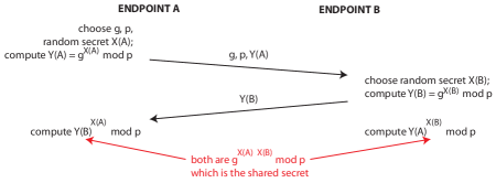
Unfortunately, the basic algorithm is vulnerable to a “man-in-the-middle” attack, which refers to any attack carried out by an adversary able to intercept packets on a link. The adversary can read, absorb, inject, or alter any packet transmitted on the link; the attacker can also “replay” packets by storing them and retransmitting them later. Figure 9 shows how such an attack would work. The adversary simply engages in a separate key exchange with each of the two endpoints. After the key exchange the adversary can relay packets transparently between and by decrypting with one key and encrypting with the other; it can also read the packets and manipulate them in any way whatsoever.
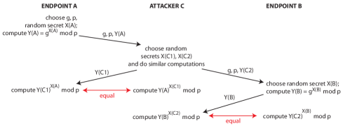
Fortunately, the solution to this problem is straightforward. and must have identities and public/private key pairs, and must authenticate each other before the key exchange. Then protocol packets must bear the sender’s digital signature. Even if the attacker can read and , it can do nothing with them.
4.3 Three IP cryptographic protocols
This section provides an overview of security in the three most important cryptographic protocols in the IP suite:
-
•
Transport Layer Security (TLS) is the successor to Secure Sockets Layer, and is an extension of TCP. Two versions of TLS, 1.2 and 1.3, are in widespread use.
-
•
Quic [34] is a new protocol proposed as an alternative to TLS. Its security mechanisms are similar to TLS 1.3.
-
•
“IPsec” refers to a family of related IP protocols, comprising the Authentication Header and Encapsulating Security Payload (ESP) protocols, each of which can be used in “transport mode” or “tunnel mode.” ESP is more useful than Authentication Header, so only ESP will be discussed here.
These protocols provide endpoint authentication, data integrity, data confidentiality, and forward secrecy. They have interesting differences, and the differences are significant for their use in compositional network architectures.
4.3.1 Protocol embeddings
TLS is composed with (embedded in) TCP (recall §3.4.1). If the Uniform Resource Locator (URL) of a Web site begins with https://, then its clients should make requests of it using IP protocol TCP and destination port 443, signifying the use of TLS embedded in TCP. Figure 10 shows packet formats for TLS, ESP in transport mode, and ESP in tunnel mode.
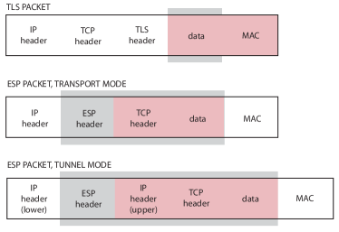
When ESP is used in composition with TCP in transport mode, TCP is simply embedded in ESP. In contrast, ESP in composition with TCP in tunnel mode is an instance of layering (recall §3.3). An entire overlay packet with IP/TCP headers and data is encapsulated in the data part of an underlay IP/ESP packet. So the important distinction between ESP transport mode (session-protocol composition with TCP) and ESP tunnel mode (layering composition with TCP) is that in tunnel mode there is an upper IP header with a completely different destination than in the lower IP header. Intuitively, the upper destination is the ultimate destination of the TCP session, while the lower destination is the next hop in the session path (see §4.4.1).
Quic is embedded in UDP, and also uses destination port 443. When a client accesses an https:// Web site for the first time, it should use TLS. If responses carry an “I support Quic” code, subsequent requests from that client to that server should use Quic, with TLS as a fallback in case of problems.
4.3.2 The setup phase
In a TLS 1.2 session, the client and server first have a TCP (control) handshake, in which they establish the session identifier and other parameters. They then begin a TLS 1.2 (control) handshake, which performs three tasks: (i) endpoint authentication (§4.2.1), (ii) negotiation of a “cipher suite,” and (iii) key exchange (§4.2.3). Usually the accepting endpoint is authenticated with a certificate and the initiating endpoint is not, because the acceptor is a server and the initiator is a client.
TLS supports many different methods for exchanging keys, encrypting data, and authenticating message integrity (see below). For each of these tasks there are many possible algorithms (counting all variations of a few basic algorithms). A “cipher suite” is a collection of algorithms and parameter choices for doing all the cryptographic tasks within a security protocol. The most important parameter choices govern key length, because key length has a big effect on the overall security of cryptography. To negotiate a cipher suite, the initiator sends all the cipher suites it implements, and the acceptor chooses one that it also implements and sends back the choice.
The TLS 1.2 handshake adds two round-trip times for TLS setup on top of the one round-trip for TCP setup. Slightly simplified, there is one round-trip for authentication and negotiation, and one for key exchange. The property of forward secrecy is achieved because fresh symmetric keys are computed for each session.
Security in TLS 1.3 is very similar to the security in Quic. One difference between TLS 1.2 and Quic (or TLS 1.3) is that Quic disallows some older cipher suites that are known to be insecure, and requires longer keys. Another difference is that Quic/TLS 1.3 setups are faster than TLS 1.2 setups.
For faster setups, Quic combines the initial transport handshake with the initial security handshake. After this there is one additional round-trip for key exchange. Further, the key-exchange round-trip can be combined with the first data round-trip, because the client’s first data request is allowed to use a less-secure symmetric key; the server’s first response and all subsequent data packets are encrypted with the final, secure symmetric keys. Even further, this one-round-trip setup can be eliminated entirely if the client has saved authentication and negotiation information from previous contact with the server. In this “zero round-trip” setup, the first round trip combines data and key exchange as above.
ESP endpoints authenticate each other if required, negotiate cipher suites, and exchange keys by means of the Internet Key Exchange (IKE) protocol. The result is that each ESP endpoint has long records called “security associations” including choices of cipher suite and actual keys. Use of full IKE to set up an ESP session is not always necessary because security associations can also be introduced into ESP endpoints by configuration, or saved from previous negotiations. Needless to say, if perfect forward secrecy is required, longer-term parts of a security association can be re-used, but there must be a new key exchange for symmetric keys.
4.3.3 Data integrity and confidentiality
In all three protocols, data and some headers are encrypted with a shared key by the sender, and decrypted using the same key by the receiver. A different shared key is used in each direction. According to the mathematics of symmetric-key cryptography, encryption satisfies the requirement of data confidentiality.
The requirement of data integrity is satisfied by the process of “message authentication.” Each packet is sent with a “message authentication code” (MAC) computed from the authenticated data by appending to the data a shared authentication key , and then applying a cryptographic hash function (§4.2.1) to . The MAC is then appended to the data in the packet. As with encryption keys, all three protocols generate authentication keys during key exchange, and use a different authentication key in each direction. The packet receiver performs the same MAC computation and expects it to result in the same MAC that it received in the packet. If an attacker inserts or changes packets while they are being transmitted, it will not be able to compute correct authentication codes for the packets, and the discrepancy will be detected by the receiver.
This algorithm alone has the limitation that an attacker with access to the packet stream can still delete, re-order, or replay packets, even though it cannot create new ones. TLS and ESP require different solutions to this problem, because of the differences in embedding visible in Figure 10.
One might think that this problem would be solved for TLS (both versions) by the fact that the enclosing TCP packets have byte sequence numbers. TCP headers are not encrypted, however, so an attacker-in-the-middle could alter them to make even an altered TCP byte stream look correct. The actual TLS solution is for each endpoint to keep track of packet sequence numbers as TLS packets are sent and received. The sequence number is not transmitted directly, but it is included in the bit string hashed to compute the MAC. For a packet to be accepted, the receiver must be re-computing its MAC with the same sequence number that the sender used. This works because TLS is embedded in TCP, so the authenticated data and MAC are presented to the authenticator reliably and in sending order.
Message authentication in ESP and Quic must work differently, because their packets may not be presented to the authenticator in sending order. In these protocols, the headers contain explicit packet sequence numbers, which are included in the data on which the MAC is computed. The authenticator cannot predict the sequence number of the next packet it will see, so it cannot detect deletion or re-ordering attacks (which, after all, might not be attacks but flaws in the network). Rather, authentication checks only for received packets with sequence numbers that have already been received, and deletes them. This is sufficient to defend against replay attacks, which are part of many man-in-the-middle attacks, because an attacker cannot change the sequence number of a packet it replays.
4.3.4 Usage of cryptographic protocols
Almost all Web traffic is now encrypted, at least with TLS 1.2. Deployments of TLS 1.3 and Quic are both growing rapidly, because of the motivation of shorter setup times. TLS is also widely used by other application protocols. ESP is most commonly used to make “virtual private networks” (see §7).
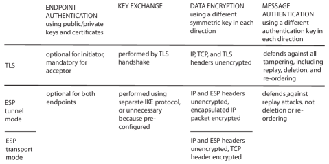
Some properties of the protocols are summarized in Figure 11. The TLS entry covers both versions. Quic is like TLS except for message authentication, in which it resembles ESP.
Not surprisingly, developers building applications on UDP are also interested in endpoint security. For UDP transmission, there is a security protocol called DTLS (Datagram Transport Layer Security) that is as similar as possible to TLS. DTLS introduces the notion that a sequence of UDP packets go together in a session, which is not present in plain UDP. It should be clear from the previous sections that, because DTLS is not embedded in TCP, its designers had to solve two problems: (i) the TLS handshake assumes reliable delivery of the handshake packets, and (ii) DTLS message authentication cannot rely on the property that packets are delivered reliably, in order, and duplicate-free, so that packet sequence numbers can be computed independently at each endpoint. DTLS solves the first problem by incorporating packet-loss detection and retransmission into the DTLS handshake. DTLS solves the second problem by using explicit sequence numbers, exactly as ESP does.
Wireless networks have their own cryptographic protocols based on the same principles. Security is particularly important for these networks, because any machine within radio range has physical access to the broadcast links of the network. When a new member joins a private wireless network, endpoint authentication ensures that the new member is authorized.
Although cryptographic algorithms and protocols are proved mathematically, there is a big difference between mathematical abstractions and code. In implementing the algorithms, efficiency is a top priority, and transformations for efficiency can introduce bugs in addition to all the other bugs to which software systems are prone. Advances in processor speeds and the exploitation of side-channels are making it easier to crack codes, so that increases in key lengths become necessary—not even counting the unpredictable disruption that might be caused by quantum computing. Cryptographic libraries are improved continually, but each machine is no more secure than its latest upgrade. It may even be less secure, when it must use an older software version to communicate with an infrequently-updated machine.
4.4 Interactions between cryptographic protocols and other aspects of networking
Cryptographic protocols have significant interactions with other security patterns, which will be discussed when the other security patterns have been presented. This section is concerned with the interactions of cryptographic protocols with network architecture and network services other than security. In considering architectural and service interactions, we will be looking at multiple composed networks as well as protocols within a single network.
4.4.1 Layering
A network with cryptographic session protocols can be layered on top of one or more networks, as explained in §3.3. Because each underlay level can implement an overlay link with a path of links, forwarders, and middleboxes, users of an overlay network must accept that its packets can pass through many machines and physical links unknown to them. But cryptographic protocols are designed to work in completely adversarial environments such as these! Furthermore, the cryptographic properties of a session can be assumed to hold for any link that it implements, so the properties guaranteed by cryptographic protocols propagate upward through layering.
4.4.2 Performance
Data encryption and message authentication increase required bandwidth and computational resources. The overhead is modest, so it is not a concern in all cases. It is more likely to be a significant concern for battery-operated devices, or for network elements that must decrypt and re-encrypt at high traffic volumes.
The most direct and significant performance costs of cryptographic protocols are incurred in the setup phase, by endpoint authentication and key exchange, which consume compute resources and increase latency. Even with short round-trip times, a small fraction of TLS 1.2 setups take 300 ms or more [43], due to increased computation time. We have seen that newer protocols have reduced setup times aggressively, often by saving and re-using session state, but this causes an inevitable loss of security [50].
The performance issue is much more serious in applications for the Internet of Things (IoT), because these applications tend to have periodic or irregular short communications from a large number of networked devices to centralized analysis or publish/subscribe servers. Message Queuing Telemetry Transport, a protocol for IoT applications, is well-designed from this perspective, because many short application communications can share the same TLS session. Even so, group events (such as initialization of a fleet of vehicles) can easily create spikes in the load on centralized servers [24].
For Message Queuing Telemetry Transport and all other application protocols with short or bursty communications separated by intervals of inactivity, it is most efficient for many communications to share a single, long-lived secure channel. Long-lived Internet channels have been difficult to maintain in the past, because various components in the path of the channel would time out and close the channel during intervals of inactivity. It is easier now—TCP, TLS, and DTLS all have keep-alive options, sending periodic keep-alive signals to keep long-lived channels open.
Architecturally, there are two ways to implement the optimization of sharing a secure channel. The first way is to embed the application protocol in the security protocol. For example, if TLS is the security protocol, application headers and data would be the data portion of TLS packets, as shown in Figure 10.
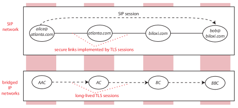
Alternatively, an application network could be layered on IP networks, as shown in Figure 12. The Session Initiation Protocol (SIP) is an application protocol for control of multimedia applications. The SIP application network has links that are implemented by TLS sessions in the IP underlay. The big difference between this architecture and protocol embedding is that the TLS sessions have different endpoints (different sources and destinations) than the SIP application session does. This makes it more flexible than protocol embedding, for two reasons: (i) The application network can insert its own middleboxes into the path of the application session, as SIP always does. (ii) The TLS sessions can last longer than any communication between two specific SIP endpoints, and can be shared by communications between many SIP endpoint pairs. Recall that embedding and layering correspond to ESP transport mode and tunnel mode, respectively.
4.4.3 Session protocols
One significant issue in the use of cryptographic protocols is their relationship to TCP, because TCP does so many things: congestion control, reliability, and packet ordering. We have seen that TLS depends on being embedded in TCP. This should not be a problem, unless real or perceived implementation constraints cause designers to make bad choices. For example, some network architectures use TCP as a session protocol in an overlay network with secure links implemented by TLS. (In comparison, in Figure 12, the overlay network uses SIP as the session protocol.) Because of the dependence of TLS on TCP, this design is layering one instance of TCP over another instance of TCP! This can cause the problem of “TCP meltdown” [25], as follows.
TCP provides reliability by detecting lost packets by means of a timer, and requesting retransmission of a packet when it does not arrive in time. For each session, TCP sets the timeout interval independently and adaptively. It can happen that the timeout interval on the upper-level instance of TCP becomes shorter than the timeout interval on the lower-level instance. In this case the lower-level session is experiencing reduced throughput, because it is waiting a longer time for each packet. At the same time, the upper-level session is having frequent timeouts, making frequent requests for retransmission, and therefore demanding increased throughput. This mismatch drastically degrades the end-to-end throughput.
Another significant issue is the relationship between cryptographic protocols and stateful firewalls in IP networks. Stateful firewalls record ongoing sessions and use them to filter packets; for example, firewalls at the edges of private networks are often configured to allow only two-way sessions initiated from inside the network. To do this, the firewall must be able to tell which incoming packets are in the same session as particular outgoing packets.
The problem in IP networks is that session identifiers are not standardized across all session protocols. All firewalls recognize TCP sessions, because the first 32 bits of a TCP header consists of two port numbers, and a session is identified by the IP destination name in each direction and its corresponding port. In ESP, on the other hand, the first 32 bits of the protocol header are a pointer to a security association (see §4.3.2), which is completely different in the forward and reverse directions, and cannot be used to associate packets in the two directions. The consequence is that a stateful firewall will not allow ESP sessions.
In this case protocol composition enables a workaround to the problem. ESP, whether in tunnel or transport mode, can be embedded in UDP with well-known port 4500. (A well-known port for UDP/ESP composition is necessary because UDP headers have no place for the “next header,” as IP and ESP headers do.) In this way a two-way sequence of UDP packets forms an identifiable session, and a stateful firewall does not see the ESP headers at all. Quic is already embedded in UDP, and traverses stateful firewalls in the same way.
4.4.4 Mobility
In its strongest sense, mobility enables a session to persist even though the network attachment of a device at its endpoint is changing. This usually means that, at some level of the layering hierarchy, the network member on the device is changing names within its network, or dying and being replaced by a member of another network. For example, when a mobile phone moves from one cellular provider’s network to another, its IP name (for data service) must change. Ideally the data sessions of the phone would persist across such moves, as its voice sessions do.
There is usually no interaction between mobility and cryptographic protocols, because the identity of a mobile machine is at a higher level than the names that change. For instance, consider a Web server running on a virtual machine in a cloud. Because of failures or resource changes, the virtual machine may migrate to a different physical machine where it has a different IP name. But the identity of the Web server is its domain name, which is at a higher level and does not change. Similarly, more than one server can have the same identity, as when a Web site of origin delegates its identity to a content-delivery server by sharing its certificate and keys.
On the other hand, thinking about mobility brings up the possibility of normal mobility in reverse—the higher-level identity moves or changes while the lower-level name remains the same. This can be a security issue: after Jane Q. Public enters her password (§4.1), she might walk away from her machine, and then any other person who walks by could retrieve her personal data and request transactions on her bank account. For this reason, secure distributed applications require periodic re-authentications of the identity of the person using them, especially after idle periods.
4.4.5 Infrastructure control protocols
Control protocols are used by network infrastructure to maintain and distribute network state. It is important to protect these protocols against subversion attacks (§2.1.2).
Unsurprisingly, some control protocols incorporate cryptography. For instance, Border Gateway Protocol Security is a security extension to BGP that provides cryptographic verification of packets advertising routes. Similarly, Domain Name System Security Extension protects DNS lookups by returning records with digital signatures.
In many cases, however, it is difficult for control protocols to rely on cryptography. An endpoint might not have a certificate or other credential to prove its identity. The protocol might require high-speed, high-volume operation. Or, the protocol might simply be too old to incorporate cryptography, even if it is feasible.
In these cases there are lighter-weight measures that can help. Network members that make requests should keep track of their pending requests and not accept unsolicited replies. Replies should be checked for credibility, whenever that is possible. Most effectively, a network member can include a nonce or random field value in a session-initiation or request packet. Subsequent packets of the session must have the same nonce or random value, so that no attacker without access to the previous packets of the session can send packets purporting to be part of it. Without the nonce, an attacker could do something to trigger a query, then send a spurious answer to the query.
5 Traffic filtering
Traffic filtering is performed by forwarders and middleboxes that are part of a network’s infrastructure. The network’s routing ensures that designated traffic passes through one of these traffic filters, and the filter examines it for evidence of flooding attacks, subversion attacks, or policy violations. If traffic seems to be part of an attack, the filter takes some defensive action, most often simply discarding the traffic.
Content-based traffic filtering (§5.1) looks at the contents of individual packets or sequences of packets. Path-based traffic filtering (§5.2) adds to this information about the paths along which traffic has traveled.
As in §4, the usual context of the discussion in this section will be a single network of any kind, or a set of similar bridged networks such as the bridged IP networks of the Internet. After explaining traffic filtering in individual networks, we return to the compositional view (§5.3), considering how traffic filtering interacts with other network mechanisms and where it should be placed in a compositional network architecture.
5.1 Content-based traffic filtering
5.1.1 Signature-based-filtering criteria
Filtering criteria are predicates used to identify suspected traffic. Signature-based filtering criteria examine specific header and data fields of packets. These criteria are used to detect most policy violations and subversion attacks. Often the criteria are Boolean combinations of simple predicates such as destinationPort = 80 on the values of IP header fields. For example, suppose that an IP “firewall” (traffic filter) at the edge of a network is enforcing this policy: the only external traffic is for Web accesses, which of course require DNS queries. The direction of a packet (inbound or outbound) can be determined from its source and destination names or from the link on which it arrives. The firewall might be configured with these four rules:
-
1.
Drop all outbound TCP packets unless they have destination port 80.
-
2.
Drop all inbound TCP packets unless they have source port 80 and the TCP ACK bit is set.
-
3.
Drop all outbound UDP packets unless they have destination port 53.
-
4.
Drop all inbound UDP packets unless they have source port 53.
In the second rule, the ACK bit indicates that this packet is an acknowledgment of a previous packet, meaning that it is not a TCP SYN packet.
These rules are sufficient for the purpose if all packets through the firewall obey the TCP protocol exactly, but of course an attacker may not be so polite. A safer approach would be to make the firewall stateful by having it maintain a table of all ongoing TCP connections. Then the second rule above would be replaced by “Drop all inbound TCP packets unless their source and destination names and ports identify them as belong to an ongoing TCP session.” If a firewall is stateful, it is crucial that all packets of a session pass through the same firewall. This property is called “session affinity.”
For reference throughout §5.1, Figure 13 is a table summarizing characteristics of four common types of traffic filter in IP networks. The classification is at least as much historical and marketing-oriented as it is technical! It is a list of products that have sold well in the past, not a prescriptive list of which options are possible.
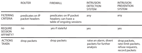
IP routers sometimes do dual duty as traffic filters. To do this, they are configured with predicates on packet headers, called “access control lists.” Routers must work even faster than firewalls, so they do not perform stateful filtering.
For filtering that looks at packet data as well as headers, networks often use commercial products known as “intrusion detection systems” and “intrusion prevention systems.” These filters can use any filtering criteria for any purpose. Signature-based filters against spam and viruses look for keywords, sometimes keywords in specific positions, and other known attack patterns. Their criteria can include regular expressions matching fields of arbitrary length. They can also be stateful, and check whether protocols are being followed. These filters can be valuable commercial products because of the intellectual property in their filtering criteria. Like all security software, to be effective, they must be kept up-to-date.
In the common case that TCP sessions are being filtered for subversion attacks or policy violations, the filter should reconstruct the correct byte stream (restoring packet order, replacing lost bytes by retransmitted ones) before filtering. If there is no reconstruction, attackers can hide attacks simply by splitting attack data over multiple packets. Even if there is reconstruction, there may be ambiguities exploitable by attackers. For example, if there are missing packets, some bytes may be retransmitted and received twice. An attacker can engineer the transmitted stream so that some bytes will have to be sent twice, and place attack bytes only in the second transmission. The filter might check only the first bytes, and the receiver might use only the second bytes. The surest way to avoid all such ambiguities is to have a “traffic normalizer” middlebox in the session path, before both filter and destination, to reconstruct a single unambiguous packet stream received by both of them [23].
One advantage enjoyed by TCP filters is that attacks require communication in both directions. Consequently, attackers cannot easily hide by giving false source names—if they did, there would be no two-way commnication. The sources of flooding attacks, on the other hand, can hide themselves behind false source names. This problem is also an opportunity, because having a false source name is a good indicator that a packet is part of a flooding attack. Forwarders (and other filters associated with them) are well-situated for using this as a filtering criteria, because forwarders have information about routing. For example, “ingress filters” in IP networks check incoming packets to see if the prefixes of their source names match expectations. This is an excellent addition to an access network, which may have detailed knowledge of its user members, or an Internet service provider’s network, which knows the IP prefixes allocated to each access network bridged with it. “Unicast reverse path forwarding” in a forwarder accepts a packet’s source name as valid only if its forwarding table specifies forwarding to the source name on the same two-way link on which the packet arrived. Unfortunately reverse-path checking cannot be used in the high-speed core of the Internet, because routes there are not necessarily symmetric.
5.1.2 Measurement and statistical analysis
Signature-based filtering criteria have two major limitations: they cannot detect new (called “zero day”) attacks, and it is difficult to use them to detect flooding attacks, whose individual packets look normal (with the exception of false source names). In response to these limitations, forwarders collect data on large amounts of traffic, and send it to other network members for analysis. Analysis can measure attributes over large collections of packets. It can then look for known attack patterns, especially of flooding attacks; for example, a single destination receiving a large number of response packets from many different sources may be the victim of a reflection attack (§2.1.1). Analysis can also detect anomalies, which are new divergences from normal traffic patterns that may indicate new attacks. Anomaly detection uses statistical algorithms, including machine learning.
For typical traffic measurement in IP networks, routers collect selected data and send it to analyzers in some well-known record format such as NetFlow or IP Flow Information Export (IPFIX). Data can be collected at multiple locations and different levels of granularity. The volume of data can be reduced by recording only headers (rather than entire packets), by sampling the packets (rather than collecting information about all packets), or by focusing on specific subsets of the packets. Most importantly, a flow comprises a group of packets close together in time that have various header fields in common. Creating a single record for a flow helps reduce the volume of data while still providing a timely and detailed view of the network traffic.
Anomaly detection is a very attractive idea, but it is also very difficult in practice. One major reason is that normal Internet traffic is highly variable, not to mention unusual-but-innocent occurrences such as congestion due to failures, or a legitimate flash crowd [38]. The other major reason is that the cost of mistakes (“false positives”) is high, as many legitimate packets are discarded. The best use of anomaly detection may be to discover and understand new attacks, then turn their characteristics into signatures or measurable patterns [52].
5.1.3 Default-reject filtering
Because the quality of filtering criteria is such a limiting factor, some of the research on flooding attacks aims to make filtering criteria precise by recognizing certain packets as desirable and rejecting all other packets. We’ll call this approach “default-reject” filtering, in contrast to usual filtering with the default behavior of accepting a packet. In addition to precision, default-reject filtering claims the advantage of preventing flooding attacks, rather than reacting to them well after they have begun.
The limitation of default-reject filtering is that it only works in limited contexts, where desirable packets can be recognized. For instance, Secure Overlay Services [30] is a default-reject proposal for public emergencies, in which all normal traffic is suspended and protected servers should be reached by emergency responders only. Another example, Ethane [11], is intended for private IP networks where control software has very complete knowledge, including the network’s user members, the people who use the machines, and the peoples’ roles in the organization that the network serves. With this much information to work with, it is possible to write very precise rules about which communications should be allowed.
5.1.4 Defensive actions
Obviously, the most common defensive action that a filter can take is to drop packets, but there are other possibilities.
The only difference between “intrusion detection systems” and “intrusion prevention systems” is that detection systems only raise alarms, while prevention systems automatically take action against suspected attacks. It might seem that automatic action is always better (it is certainly faster), but there are good reasons for keeping operators and enterprise customers in the decision loop. If a suspected attack is a false positive, much legitimate traffic may be dropped. If an operator deploys additional resources on behalf of an enterprise customer that is under attack, the customer will have to pay for them. In rare cases, the defense against a suspected attack may even be a counter-attack, which is wrong and even dangerous (in a military setting) if not well-justified.
What actions are normally taken by intrusion prevention systems, other than dropping packets? If there is uncertainty about the packets, a filter can rate-limit them or downgrade their forwarding priority rather than dropping them. Rather than dropping session-initiation requests, a filter could reply to them with refusals, which would discourage retries. A refusal to a TCP SYN (request) is a TCP RST (reset). A refusal to an HTTP request is an error code.
Finally, when filtering is being used to defend against policy violations, sometimes the filter records packets for the purposes of investigation and legal evidence. Recorded packets are usually not dropped but forwarded on to their destinations, to keep the investigation secret from its targets until it has been completed.
5.1.5 Resources and capacity
Traffic filtering expends a lot of network resources, so the detailed design of a traffic-filtering mechanism must be resource-sensitive. How does a network ensure that its traffic filters do not themselves become traffic bottlenecks during flooding attacks?
There are two approaches to providing sufficient filtering capacity. The first is to host traffic filters on high-capacity machines dedicated to this purpose. The second is to run traffic filters on virtual machines in a cloud. In this approach it is possible to implement “dynamic scale-out,” which means that as the load increases during an attack, more virtual machines are allocated for the filtering task. All the filter types in Figure 13 have been implemented with both approaches, although the high-capacity-machine approach is more often applied to routers and firewalls.
The situation today is fluid, as flooding attacks are becoming more severe. A recent flooding attack on a number of DNS servers [17], including amplification, generated traffic at 10-20 times normal volume, with bursts up to 40-50 times normal volume, and reportedly a maximum of 1.2 Tbps (1200 Gbps). To provide some intuition about the resources needed to handle such attacks, Figure 14 shows some typical capacities for servers and various kinds of traffic filters.
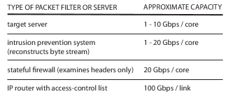
Of course these numbers are subject to frequent change. On the positive side, converting an algorithm from software to programmable hardware increases its speed by a factor of about 10, as does converting it from programmable hardware to fixed-function hardware. On the negative side, commercial intrusion-prevention systems frequently fall short of advertised capacity. There are adversarial workloads designed so that the TCP byte stream is especially difficult to reconstruct. More commonly, rule-checking is the performance problem, because it is more expensive than reconstructing the byte stream; performance is improved when necessary by dropping rules.
5.2 Path-based traffic filtering
Path-based traffic filtering augments filtering criteria based on the contents of packets, as discussed in the previous section, with criteria based on the path along which packets traveled. There are two reasons for introducing path-based filtering. The first reason is that path information can improve the precision of filtering criteria, so that fewer good packets are accidentally included. For example, say that the overall load on a server suggests a flooding attack, and intrusion detection proposes a candidate filtering rule based on packet contents. If we know that most paths to the server are delivering a trickle of these packets, and one path’s load is dominated by these packets, there is a good chance that only the packets on the dominated path are attack packets.
The second reason for path-based filtering is that it may be possible to filter out attack packets closer to their sources, which reduces the damage they do. This section will discuss the trade-offs, why path-based filtering is not much used today, and why it might be used more in the future.
5.2.1 Tracing attacks back to their sources
In IP networks, because of spoofing, the source name in a packet is not a reliable indicator of where it came from. The purpose of a traceback mechanism is to determine the path along which an attack packet travels. In other words, traceback associates path meta-data with packets.222The Accountable Internet proposal (§4.2.1) recommends authenticated source names so that, among other reasons, traceback is not needed.
From the viewpoint of a victim of a flooding attack, the network is a directed acyclic graph with many possible packet sources and a single packet sink. Often the graph is a tree, with the victim at the root. The interior of the graph consists of forwarders and middleboxes, connected by links carrying traffic toward the victim. Figure 15 shows such a graph for attack victim . In the figure, member names also stand for names of machines.
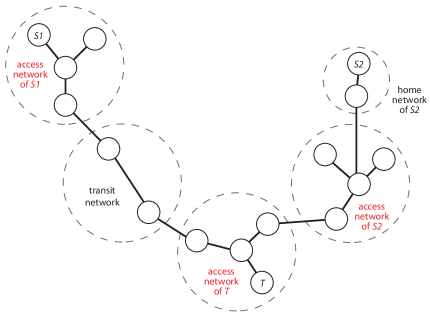
Figure 15 illustrates some relevant distinctions. The access network of a machine is the first network in all its outgoing paths whose administrative authority is different from the owner of the machine (assuming for simplicity that that there is only one such network). The access network of a machine is significant because it is the first network that is able to filter outgoing packets of the machine. Often the machine belongs to its access network, as and do. Sometimes, however, the first network of a machine (for example ) is a home network whose administrative authority is the same as the owner of the machine. In this case the machine has separate home and access networks.
The simplest traceback mechanism is the Internet Control Message Protocol Traceback packet. The idea is that each forwarder samples the packets it is forwarding, with a very low sampling rate. When a packet is chosen, the forwarder encloses the whole packet, along with the names of itself, the preceding forwarder, and the succeeding one, in a Traceback packet, and sends it to the packet destination. The idea is that the victim or a nearby helper will reconstruct whole paths and maintain a running view of where its packets are coming from. In addition to cumulative overhead, the chief disadvantage of Traceback packets is that attackers could forge them. To prevent this, the sources of Traceback packets must be authenticated with public-key cryptography, introducing significant additional overhead.
In other traceback mechanisms, forwarders mark the packets themselves with path information as they are forwarded toward the victim. The markings allow the victim or a helper near the victim to reconstruct the path along which packets of an attack traveled.
The design of these traceback mechanisms entails many trade-offs. In the remainder of this section we use representative proposals to illustrate the issues and indicate some of the trade-offs, without declaring any particular winners.
Internet measurements indicate that the average-length path has 10-15 forwarders, and 20-25 is a practical maximum [12]. It would take a large amount of space in packets to represent full paths. One design allocates space in packets to record only a single forwarder (32 bits for an IP name), and uses probabilistic marking, in which each forwarder marks a packet with probability , say 0.04 [48]. Because forwarders late in the path overwrite the marks of earlier forwarders when they mark, the forwarders in a path can be ordered by the frequency of their marks. The disadvantages of simple probabilistic marking are:
-
•
A path cannot be reconstructed until hundreds or thousands of attack packets have been received.
-
•
The attack signature may very well include attack packets from more than one source, because of botnets and coordinated attacks. If there are multiple attack paths to a target, then collectively they will form a tree. Mark frequency is not enough information to reconstruct a tree, because mark frequencies only result in a linear order.
The final IP Traceback design [48] deals with the problem of multiple attack paths in simple probabilistic marking by encoding edges (node pairs representing links) in the tree rather than nodes. The resulting doubling of the space needed for marks is dealt with by very aggressive compression techniques, primarily making each mark field contain only a fragment of the full-size mark. This reduces the mark field to 16 bits, but has the effect that many more packets must be received before the path can be reconstructed. Even so, simulations show that a path of length 15 can almost always be reconstructed after the victim or its representative has received 2500 attack packets. The main disadvantage of this is that the reconstructed tree of multiple attack paths becomes the solution to a large combinatorial puzzle.
The Pi design [56] has every forwarder (at least, within a specified path segment) mark the packet. Because the mark encodes the entire path (or segment), the victim’s helper need only receive one marked packet to have all the information available about the path. Deterministic marking is combined with very aggressive compression of the mark field, again down to 16 bits. Primarily, compression in this proposal means that more than one path can result in the same mark. The disadvantages of Pi are:
-
•
Marks do not have enough information to reconstruct paths, only to distinguish equivalence classes of paths (all the possible paths that happen to map to the same mark). So marks are not helpful in locating or distributing traffic filters—all the filtering must be done near the victim.
-
•
Marking and filtering require choosing three parameters, each difficult to choose in general and having interactions with many other factors, including the ability of attackers to inject deceptive information.
In Active Internet Traffic Filtering [4], every packet is marked with full names, but usually only by the egress forwarder at the edge of the source’s access network, and the ingress forwarder at the target’s access network. If a source/destination pair seems to distinguish an attack, a controller in the target’s network will request both the target-network forwarder and the source-network forwarder to drop such packets (see below). The source-network forwarder includes a nonce in the mark, and the controller copies it into the request, which is how request packets are secured (as in §4.4.5).
5.2.2 Filtering upstream
In the Internet, at any given time, there is a relatively small number of targets for active flooding attacks. To defend a target against these attacks, traffic filters can conceivably be placed in the graph of paths downstream, near the target, or upstream, near packet sources. There are three main advantages to placing traffic filters upstream:
-
•
If filtering is farther from the target, the damage done by attack traffic is lessened, because attack traffic is carried for shorter distances along fewer links. Note that the damage of a flooding attack is not limited to the intended target, because traffic to many other destinations will also suffer because of congested links.
-
•
If a traffic filter is close to sources of attack traffic, it may have more information about the sources. The access network sees all of a suspected source’s traffic, so attack patterns are more likely to be detectable. An access network may also know more about the type and reputation of its sources (device type is relevant because some operating systems and vendor hardware are more easily penetrated than others). More precise filtering means less collateral damage.
-
•
Very often, attack packets are coming from a botnet, with a large number of sources well-distributed across the public Internet. So the total amount of available filtering resources near sources greatly exceeds the total amount of resources available near a target.
A third option, filtering in the topological core of the network, is never used because the core is a region of high-speed links and high-speed forwarders handling large numbers of packets. The required speed of filtering, and the potentially large number of filtering rules to be checked, makes this option infeasible.
Pushback [38] is a simple scheme for reducing overall congestion by pushing filtering upstream. At a forwarder, congestion on an outgoing link is diagnosed when there is frequent packet loss (packets must be dropped because there is no room for them in the link’s output queue). If a particular aggregate of packets is responsible for a significant portion of the link’s traffic, then a predicate describing the aggregate becomes a filtering criterion. The forwarder sends upstream, on all its input links carrying packets in the aggregate, a request to rate-limit these packets. Upstream forwarders can also request pushback recursively, so pushback incorporates its own traceback mechanism. By rate-limiting only specific aggregates along specific paths, pushback aims to do just enough to protect other traffic, while limiting collateral damage.
The Active Internet Traffic Filtering proposal [4] employs upstream filtering because it is particularly concerned with the botnet case, and with using the many forwarders in the access networks of bots to help filter. There are several ways in which its basic idea (above) must be augmented to make it reliable and secure. First, the request and acknowledgment packets of the control protocol itself could be used to flood a network, so they must be rate-limited. Second, there is a set of mechanisms through which forwarders are monitored to see if they are keeping their filtering promises, and through which filtering can be delegated to other forwarders along an attack path.
5.2.3 Capabilities
In the long struggle to defend public servers against flooding attacks, researchers have explored an alternative approach based on “capabilities” (a capability is an unforgeable record showing the rights of the bearer). The idea behind capabilities is that no source should be able to send Internet packets to a destination unless the destination has already approved the transmission.
As applied to the protection of a public server accessed through TCP, the TCP SYN is interpreted as a send request to the destination. Unless the source is already on a blacklist, the server will grant permission to send a limited number of packets in a limited period of time, and reply to the SYN with a capability attesting to the permission. The sender includes the capability in subsequent packets, and forwarders on the path enforce the capability policies. The destination can grant permission for more packets later, if they are needed and the source has been well-behaved. Packets with no capabilities, expired capabilities, or incorrect capabilities may be delivered, but with the very lowest priority.
An example of this approach is the Traffic Validation Architecture [57]. The architecture includes elaborate mechanisms to ensure that capabilities cannot be forged by attackers, and cannot be transferred to other attackers. It includes mechanisms to reduce the amount of space needed in packets for capabilities, which can be considerable. It also has mechanisms for reducing the amount of state in forwarders required to implement the security measures and to track packets sent and time elapsed.
The principal problem with capabilities is session requests, which cannot be controlled with capabilities and can be used on their own to create flooding attacks. The Traffic Validation Architecture handles this problem by rate-limiting request packets to 5% of the total volume. It can be shown, however, that this just turns a flood of request packets into a denial-of-capabilities attack, in which legitimate senders cannot get their requests through [5].
5.2.4 Filtering downstream
The advantages of filtering upstream are balanced by two major disadvantages:
-
•
Upstream networks may not have sufficient incentive to use their resources to protect targets that are remote from them. It has been argued that networks under attack might be more willing to accept incoming packets from cooperating upstream networks, which will give the users of the upstream networks better service [4]. Historically, however, cooperation between the networks of different operators has been scarce [22].
-
•
Even if source networks are willing to cooperate with target networks, the necessary coordination is not easy. Previous sections have illustrated many forms of overhead and many security vulnerabilities introduced by coordination.
The proposals for moving filtering toward the sources of attack traffic date from the early 2000s. In the 2010s cloud computing advanced so far that it altered the evaluation of trade-offs decisively. Now almost all traffic filtering is performed on behalf of the access networks of attack targets. It is usually performed in clouds, with virtualized filters and dynamic scale-out. Sequenced filters allow simple filters to deflect suspicious packets to complex filters for more detailed screening.
The reader might be wondering why we went through all the detail of §5.2.1 through §5.2.3 if most of it is irrelevant today. The point is that it was made irrelevant by technology changes that altered the evaluation of trade-offs, and technology changes in networking are not finished. Future changes could easily make old solutions interesting again. Here are three examples:
-
•
If the Internet evolves to offer more paths with reserved bandwidth for real-time applications, then capabilities might be an excellent approach to securing the use of reserved paths.
-
•
Individual IP networks (under single ownership) now seem to be growing in size and geographical scope. If this trend continues, it will become more common for both the upstream and downstream segments of a path to an attack target to be controlled by the same operator. If so, then the administrative barriers to upstream filtering will disappear.
-
•
Most traceback proposals require IP forwarders to perform new functions—marking and filtering packets in new ways. Now that programmable forwarders are coming into more common use, it will become much easier for network operators to experiment with traceback and other such schemes.
5.3 Interactions between traffic filtering and other aspects of networking
5.3.1 Routing
For a filtering tree or graph (as in Figure 15) to work correctly, all packets destined for the protected target must pass through one or more forwarders or middleboxes acting as filters, in accordance with the intended design. This is the province of routing, which populates the forwarding tables used by forwarders. Routing is performed in several different ways—sometimes by a distributed algorithm that forwarders run among themselves, and sometimes by a centralized algorithm running in a separate controller.
Routing packets through a filtering tree may seem straightforward, but there is a different tree for each destination, and routing algorithms are also concerned with reachability, performance, fault-tolerance, and other policy constraints. For this reason, there has been considerable research on verifying that forwarding tables are correct, or on generating them correctly, where the correctness criteria include “waypointing” constraints about steering packets through filters [7, 8, 18, 29, 37].
Another issue that complicates routing through a filtering tree is the fact that many traffic filters require session affinity—all the packets of a session, in both directions, must go through the same filter. Wide-area routing frequently creates different paths for packets traveling in different directions between the same two endpoints. Even packets traveling in the same direction may be spread across multiple paths because there has been a failure in one of the paths, or a need for better load-balancing. Within a cloud, where many virtual machines are running the same filtering software for scalability, a session can be assigned to any virtual machine. The assignment must be remembered, however, so that all packets of the session are steered in the right direction. Shortcuts such as “assign a session to one of four virtual machines based on the last two bits of some identifier” work well in static situations, but fail when filtering resources must be scaled up or down because of fluctuations in load.
5.3.2 Layering
Almost always, a packet arriving at a machine is being transmitted through multiple layered networks simultaneously, for example an Ethernet local area network, an IP network, and an application network. Figures 3 and 6 combined illustrate this simple example. In addition, layered between the application network and the lowest IP network there is often a virtual private network (§7.2.2) or other IP network. If the machine is actually a virtual machine in a multi-tenant cloud, there is sure to be at least one network between the tenant’s IP network and the Ethernet, with the job of sharing cloud resources among all tenants.
The layers are significant because attacks can take place in any of them. This is both a challenge and an opportunity. If only packets in the lower layers are filtered, then many higher-level attacks will be concealed in the higher-level packets, which are mere data to the lower-level networks. For example, recall that IP intrusion detection systems look into packet contents for signs of malware at specific locations. These systems are assuming there are no networks layered between the filtering network and the application network; if there are additional networks, then the packet formats will be different, and the filtering criteria will be useless.
On the other hand, much can be gained by filtering packets separately in each network. Already there are special filters for Web requests and email messages, which are packets in their own application-oriented networks. These filters are deployed as middleboxes in these networks. This idea can be extended to intermediary layers, where each filter is attuned to the configuration, protocols, and vulnerabilities of its particular network. It is often possible to optimize architectures so that filters at multiple levels can be located on the same machines.
The second interaction between filtering and layering concerns networks below the filtering network in the layer hierarchy. Imagine that you have designed a filtering mechanism within a network, and convinced yourself that it is correct. Your argument concerns (among other things) paths in the network to a potential attack target, and shows that routing places an appropriate traffic filter in every path.
Whether you remembered to state it or not, your argument that no (or a limited number of) attack packets reach the target depends on the assumption that attack packets do not suddenly appear inside the perimeter of traffic filters. It is easy enough to check that the network members inside the perimeter are part of the network infrastructure and therefore trusted, but what about the links? It must be ensured that no packet is received on trusted link that was not sent on the link. If the link is implemented rather than physical, it must be proved that the implementing network does not inject packets into the implementation of the link.
This might seem like a fanciful concern, but it is not. An Ethernet can be penetrated physically, and it is easy to make a penetrated Ethernet inject packets into the links of networks layered on it [32]. In a multi-tenant cloud, the links of a tenant’s network (where the filtering will take place) are virtual links implemented by sessions in the lower-level network that shares resources among tenants. If the cloud network does not isolate tenants properly, then packets sent by virtual machines of a different tenant could be delivered as part of this tenant’s sessions.
5.3.3 Cryptographic protocols
There is a profound interaction between cryptographic protocols and traffic filtering. If a user session is encrypted, then middleboxes in general, and traffic filters in particular, cannot read anything in the session packets beyond their headers. One response to this interaction is increased interest in filtering based on traffic attributes that encryption does not change, e.g., packet timing and sizes. It may be too early to tell how effective this will be as a defense, considering that its recognized successes are spying and tampering attacks [42].
In some cases the relationship between users and filters is not adversarial, and there are three techniques for managing this interaction in more-or-less cooperative cases. Before presenting these techniques, we will explain the interested parties and their powers. We can think of their interactions as a game, one instance of which is illustrated by Figure 16. At the top of the figure we see what the initiating user can do. It chooses the acceptor of the session, and if the acceptor agrees, the data of the session will be encrypted end-to-end.
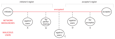
At the second level of the figure, we see what the network can do. The network has the power to insert middleboxes anywhere in the path of the user session, simply by routing session packets through them. The figure shows some common middleboxes, inserted in likely places, which are often in regions of the session path near the two endpoints. A middlebox might have the purpose of enhancing performance, for example by caching or compression (). For maximum effectiveness, it should be placed near the initiator, as shown. A middlebox might be a traffic filter, with the purpose of protecting the acceptor from subversion attacks or policy violations that might damage it (). This middlebox will probably be placed near the acceptor. Finally, the network might insert traffic filters that are working against the interests of the initiator and acceptor, either by preventing them from violating policies, or by spying on or tampering with their communication ( and ). These middleboxes might be placed in either region.
At the third level of the figure, we see that other malicious parties can also insert middleboxes in the path by various techniques such as wiretapping, for the purposes of spying and tampering (). Fortunately, physical security and security mechanisms in other networks constrain such attacks. In the illustrated example, a malicious party is able to eavesdrop in the middle of the session path, but not near the endpoints.
If network middleboxes are working on behalf of the user endpoints of an encrypted session, and if they need to read data to do their work, then the cleanest arrangement is to make the middleboxes part of an application-oriented overlay network. This is illustrated by a SIP network in Figure 12. In the figure, data traveling on the links of the SIP network is encrypted by TLS in the IP networks, but each middlebox in the SIP network receives and sends plaintext.
The second and third techniques can be deployed within the bridged IP networks of the Internet. In the second technique, the network introduces another middlebox that is a proxy. The proxy would accept the initiator’s TLS session and make a TCP session between itself and the original acceptor. The proxy would decrypt packets from the initiator and send their contents in plaintext packets to the acceptor, so they could be read by any middleboxes in the path of the TCP session.
If the acceptor is a public server, the limitation on this technique is that the acceptor must trust and approve of the proxy, so that the server is willing to lend the proxy its identity and secret keys. So the only place in Figure 16 that a proxy could plausibly be inserted is between and .
The general idea of proxies that cooperate with endpoints is developed further in Middlebox TLS (mbTLS) [44]. In this approach all middleboxes must be proxies, and they create a session consisting of an end-to-end chain of simple TCP sessions. Along the chain from initiator to acceptor, there is first a set of middleboxes inserted on behalf of the initiator, followed by a set inserted on behalf of the acceptor (see Figure 17).
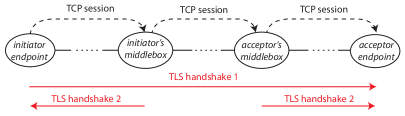
Within the end-to-end chain of TCP sessions, the initiator and acceptor first have a normal end-to-end TLS handshake for endpoint authentication and key exchange. Then each middlebox initiates a secondary TLS handshake with the next element in the direction of its sponsoring endpoint. For example, if there are two middleboxes M1 and M2 inserted on behalf of the initiator, M2 initiates a secondary handshake with M1, and M1 with the initiator. The secondary handshakes exchange symmetric and authentication keys for the individual simple sessions. They can also perform endpoint authentication of middlebox identity (in this case the responsible owner), software version and configuration, security properties of the hardware/software platform, etc. This makes sense because the middleboxes associated with each endpoint are working in cooperation with it, even if they have an adversarial relationship with the middleboxes of the other endpoint.
After the secondary TLS handshakes, data is transmitted. In each middlebox data is decrypted, processed as plaintext by the middlebox application code, then encrypted again for the next hop.333An earlier version, Multi-Context TLS [45], allowed the endpoints to place constraints on the read/write access of middleboxes. Note that the “midpoint” simple session between initiator and acceptor middleboxes has no secondary handshake; in this simple session, the keys chosen by the primary TLS handshake are used.
The third and final technique aims to preserve both middlebox functionality and user privacy, based on new results in cryptography. At one extreme, fully homomorphic encryption [20] makes it possible to compute any function on encrypted data without learning more about the data than the function’s value. Although fully homomorphic encryption is currently impractical (it is too expensive computationally, by orders of magnitude), there are less capable algorithms for computing functions on encrypted data with performance that may be feasible for current use.
BlindBox [51] is a proposal for allowing middleboxes to operate on encrypted data. BlindBox middleboxes can apply detection rules of the kind commonly used by virus scanners, intrusion-detection systems, and parental filters. The scheme also allows a middlebox that has found a keyword or other suspicious string, as probable cause of a security violation, to decrypt the entire packet.
BlindBox is implemented as an extension of TLS. In addition to the basic TLS handshake, endpoints must generate extra keys. The data must be sent end-to-end twice (redundantly), once in the ordinary TLS form and once in a reformatted and re-encrypted form suitable for the BlindBox algorithms.
The biggest overhead incurred by BlindBox is due to rule preparation, because the middlebox must have the rules themselves encrypted with a session-dependent key. The endpoints must not know the rules (this would make them easier to evade) and the middlebox must not know the key (otherwise the guarantee of data confidentiality would be lost). So who can encrypt the rules? For every keyword in every rule, both endpoints must generate and transmit to the middlebox a special encryption function that incorporates yet obfuscates the session-dependent key. The middlebox must first check the two for agreement (in case one of the endpoints is insecure) and then apply the encryption function to the rule. This results in very high performance overhead, which means that BlindBox is currently practical only for long-lived sessions or small rule sets.
Although both Middlebox TLS and BlindBox are promising efforts, it seems clear that their complexity and non-uniform communication among participants are weaknesses. Complexity itself is a security vulnerability, because it provides a larger “attack surface” for adversaries to probe.
5.3.4 Session protocols
There is a general problem affecting all protocols of the IP protocol suite: When a new network feature requires additional information in packets, where can the information be put? Inventors do not wish to increase packet size, and want their proposals to have backward compatibility. So they generally choose to fit their information into some “unused” field in current header formats. For example, both IP Traceback [48] and Pi [56] squeeze traceback information into the 16-bit identification field in the IP packet header. The original use of this field is to group fragments of a fragmented packet so they can be re-assembled at their destination. It is declared “unused” on the grounds that fragmentation of IP packets is now rare.
The irony of such proposals is that so many new features and protocol variations use the same “unused” fields. At the same time, inventors of other new functions have no compunction in deleting this “unused” information from packets when it is convenient. For example, a server using SYN cookies (§6) effectively drops all optional information in TCP SYN packets, which means that any network feature relying on extensions to TCP is disabled. Note that many servers using SYN cookies are Web servers, and many new features relying on extensions to TCP (such as Multipath TCP [46], just to name one example) have improved Web access as a major use case.
A possible solution to such problems is a generalized mechanism for composition of session protocols. This mechanism would build on the structures of Figure 4. If all session protocols could be composed freely, then all new features requiring space in packets could be introduced—without fear of interference—as new, composable session protocols. For instance, just as TLS is composed with (embedded in) TCP, TCP could be composed with (embedded in) Multipath TCP. TCP would control transmission of byte streams along individual paths, while Multipath TCP would coordinate the multiple byte streams. Unfortunately this solution may not be backward-compatible, and also raises concerns about generating packets that exceed the maximum packet size of their network.
6 Dynamic resource allocation
Because flooding attacks are resource wars, both network infrastructure and user members can defend against them by allocating more resources when they are under attack. Cloud computing has made it easier for networks to scale out traffic filters, and for users to scale out servers. Even in server-centric defenses the network is usually involved, for two reasons: (i) even when server resources are sufficient to absorb an attack, network bandwidth must also be sufficient to handle the attack, and (ii) the network provides the service of distributing the load across servers.
Dynamic resource allocation works better if resource replicas are geographically distributed, so that some replicas can be reached when other parts of the network are too congested. Because attacks on DNS servers are so common and damaging, it is especially important to have distributed authoritative DNS servers for popular domain names. Queries are distributed across the replicas by means of IP anycast. If there are five replicas sharing the load and one has been overwhelmed by an attack, IP anycast may not be dynamic enough to redirect queries away from the failed replica, but at least queries directed by anycast to the other four will succeed. In Figure 18 there are three authoritative DNS servers for the domain example.com; IP anycast directs the client’s query to the closest one.
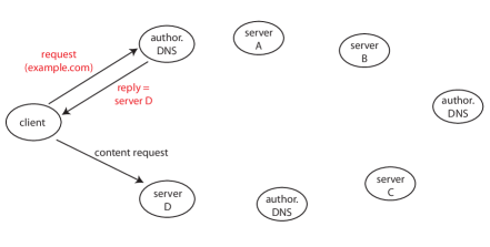
A “content-delivery network” provides many replicas of its customers’ content, geographically distributed so that the latency of content delivery to each client is minimized. In Figure 18 the authoritative DNS servers for customer domain example.com are aware that its content is available at servers A through D, and also maintain information about location and recent performance of the servers. So each DNS server can return to a client the IP name of the best content server for it to contact.
Replication of service resources is easiest when servers are responding to queries based on fairly static data. When queries can update service data, the service implementation must do extra work to keep the data replicas in some adequate state of consistency. (The study of distributed computing has produced many algorithms for replicated data, satisfying many different definitions of consistency.) In some cases dynamic data can be distributed across multiple sites more easily by sharding, e.g., by partitioning the keys of a key-value store so that each site is responsible for a subset of the keys. No one key-value pair will be replicated, but the total resources available will be greater.
Instead of dynamically allocating more server resources during attacks, the same result can be achieved by dynamically reducing the work per request that servers perform. For example, a flood of DNS queries is amplified when servers query other servers. A very effective defense against these attacks is longer times-to-live for cache entries, perhaps 30 minutes, in recursive and local DNS servers [41]. If local entries are cached longer, there will be fewer queries and retries made to authoritative servers. There are many good reasons for DNS cache entries with short times-to-live, but these can be changed as an adaptive measure during attacks. The same idea would work for many other services with caching.
SYN floods (§2.1.1) are such a serious problem that several specialized techniques have been developed for reducing server work per SYN, and these may be in use at all times rather than turned on just during attacks. In a “SYN cookie” defense, the server responds to a SYN with a SYN+ACK packet having a specially-coded initial sequence number (the cookie). It then discards the SYN, using no additional resources for it. If the SYN was an attack, it has caused little damage. If the SYN was legitimate, on the other hand, it will elicit an ACK from the initiator with the same initial sequence number incremented by one. By decoding the sequence number, the server can reconstruct the original SYN and then set up a real TCP connection.
There is another resource defense against SYN floods that is less efficient than SYN cookies, but comes with fewer side-effects (see §5.3.4). This defense uses a middlebox in the path to a Web server that stores and responds to SYN packets, but does nothing else with a SYN packet until it receives the ACK that completes the handshake. On receiving the ACK, the middlebox forms a new session by sending the SYN to the server, and subsequently acts as a transparent forwarder between the two sessions. If the middlebox does not receive a timely ACK, then the SYN packet was part of an attack or the client has failed, so the middlebox drops it.
Viewed globally, dynamic resource allocation is not much different from static allocation, so its interactions with other aspects of networking are already understood. As indicated, services under attack may be available in some locations and not in others.
7 Compound sessions and overlays for security
Like cryptographic protocols, compound session and overlays are mechanisms employed by users to defend themselves against spying and tampering attacks (§2.1.4). Cryptography alone is not sufficient because it does not conceal packet headers.
The focus of this section is on middleboxes. Traffic filters are middleboxes, inserted by networks into session paths by means of routing. In §3.4.2 we saw that users can also insert middleboxes into their session paths, by introducing proxies that form the endpoints of simple sessions in a compound session. Packet headers within simple sessions must be correct so that packets are delivered, but the end-to-end identity of a compound session is concealed by its multiple headers.
Proxies have a lot of power: they can perform many kinds of computation on packets, so that packets in two associated simple sessions need not correspond one-to-one. They can even translate from one session protocol to another, so that two associated simple sessions use different protocols. A proxy can get the name of the next proxy or endpoint in the compound session by using the session protocol to engage in a dialogue with the initiator.
Spying and tampering attacks can be launched by other user members of a network (authorized or unauthorized), and, most importantly, by infrastructure members of a network performing traffic filtering. Thus the entire topic of this section can be seen as an interaction between two patterns, namely compound sessions and traffic filtering.
Compound sessions are useful in many situations, but they have some limitations. After covering compound sessions, we will introduce overlays for security. These use explicit layering to create implicit compound sessions, and can do more for users than compound sessions alone.
7.1 Compound sessions
7.1.1 Proxies in access networks
Perhaps the oldest example of a proxy for evading traffic filtering is an “application gateway,” which is installed in a private IP network for the benign purpose of evading the too-simple filtering imposed by a firewall. For example, an enterprise firewall may block all outgoing sessions except Web accesses. However, the enterprise may also wish to allow outgoing sessions of another kind, when they are initiated by specific users. The firewall cannot enforce this policy because it does not know the mapping between internal IP names and users (and the mapping may not even be static).
An application gateway for the application, for instance Telnet, solves this problem, as shown in Figure 19. To use it, a user initiates a Telnet session to the application gateway inside the enterprise network. The gateway is a Telnet proxy. By means of an extension to the Telnet protocol, which is embedded in TCP, the user supplies a password to authenticate himself to the gateway, and also the name of the real Telnet acceptor. The gateway initiates a Telnet session to the real acceptor outside the enterprise network, and joins the two simple sessions in a compound session. The enterprise firewall allows outgoing Telnet sessions from the application gateway only.
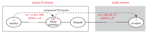
In this example, the operator of the enterprise network is cooperating with the user by providing the gateway. For the operator, it is easier and more efficient to provide the required user functions with an application gateway than with a greatly-enhanced firewall.
In a similarly cooperative situation, the operator of a private network might provide a proxy (with a public name) that session initiators outside the network can connect to. The proxy authenticates the initiator as deserving the rights of members of the private network. Then, through the proxy, the initiator can connect to any member of the private network.
7.1.2 Proxies in transit networks
A user can evade filtering in his access network more easily by connecting to a friendly proxy in another network. This will be illustrated by the use of a proxy to reach a Web server. This kind of proxy is sometimes called a “virtual private network.”444Calling a proxy a network is a misnomer. See §7.2.2 for the real thing.
In Figure 20 a secure dynamic link in a Web-based application network is implemented by a compound TLS session in bridged IP networks. First the browser’s request causes initiation of a TLS session with a friendly proxy outside the client’s access network. A proxied TLS session is like a normal TLS session except that: (i) instead of looking up the domain name dangerous.com and using its IP name as the destination of the session, the client’s IP interface uses the proxy’s IP name as the destination of the session; (ii) the client’s IP interface expects and verifies the certificate of the proxy, not the Web site; (iii) the proxy decrypts the HTTP request in the TLS data, looks up the domain name, and uses the result of the lookup as the destination of an outgoing TLS session. After this the proxy relays packets between the two simple sessions of the compound TLS session (note that the proxy must decrypt and re-encrypt the data in each packet, because symmetric keys in the two simple sessions are different).
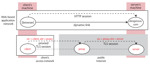
Because of the compound session formed by the proxy, the client’s access network does not know what server the client is connected to, so the client has privacy from spying and tampering in his access network. The client also has anonymity at the server, because the server has no information about the client.
One disadvantage of this mechanism is that the client has no privacy from the proxy. Another disadvantage comes from the fact that the names of helpful proxies are usually publicly available (so users can find them), which means that they are available to the user’s adversaries as well. Consequently, if the clients’s access network is censoring the network activity of its users, it can simply block packets destined for external proxies. These disadvantages are addressed in subsequent sections.
The proxy in Figure 20 is specialized to handle TLS sessions. There can be proxies for other session protocols as well. For example, a “recursive” DNS resolver is just a proxy for the simple request/response session protocol used for DNS lookups. ODNS [49] is a proposal for improving the privacy of users doing lookups by introducing a proxy between local DNS resolvers and authoritative resolvers.
To introduce the proxy, as shown in Figure 21, the user appends—to the domain name it intends to send in its request—the extra high-level domain name .odns. This will cause a local DNS resolver to send the request to an ODNS proxy. To conceal the true desired domain from the local DNS resolver, the user generates a symmetric key , encrypts with , and encrypts with the public key of ODNS proxies. A concatenation of these two values is the domain name it sends in its request. The ODNS proxy decrypts with its private key to get , and then decrypts with to get . After getting a response from an authoritative server for , with an IP name for , it encrypts both and with , and sends them in a response to the local DNS resolver. As a result of this design, the local DNS resolver will not know what domain name is being looked up, and the ODNS resolver will not know the identity of the user.
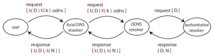
7.1.3 Deflection
The problem that a censoring access network can block packets to known proxies has been addressed by several similar proposals [26, 28, 55]. They all use proxies, but in a way that still works despite the blocking.
A typical compound session in these proposals is shown in Figure 22. The access network of the session initiator is filtering out packets from users to certain destinations, represented here by the “covert destination.” The initiator cannot evade this censorship by using a false source name, because then replies from the destination will not be delivered to the initiator (also, the network may be blocking everyone’s access to the site). The critical mechanism is that session packets are routed through a friendly network where a forwarder recognizes that the packets must be treated specially, and deflects them to a proxy similar to the proxy in Figure 20.
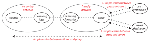
For deflection to work, the initiator must give a hidden signal to the deflecting forwarder—one that the censoring network is unlikely to recognize—so the deflecting forwarder knows which packets to deflect. In Cirripede [26], the user registers with the friendly network; while the registration is active, all sessions initiated by the user are deflected. In decoy routing [28], this is done on a session-by-session basis. Decoy routing assumes that the initiator and proxy share a secret key, which is combined by the initiator with time-varying information to form a hidden detection signal for a session. The signal goes into a pseudo-random field of the first TLS packet. The decoy-routing system has the same information as all the initiators, so it can tell the deflecting forwarders which signals to look for at the current time.
In Figure 22, the TLS-based session protocol between the initiator and the proxy is complex. When the proxy first receives session packets, it initiates a TLS session to the overt destination. The TLS handshake is completed end-to-end between initiator and overt destination, so that all packets (including a certificate in plaintext) look normal to the censoring network. Once packet data can be encrypted, the proxy signals to the initiator that it is in the session path, terminates the session to the overt destination, gets the name of the covert destination from the initiator, initiates a session to the covert destination, and relays packets between the client and covert destination. During the entire compound session, the packets seen by the censoring filter will have the overt destination in their source or destination field.
The final problem to be solved is the placement of deflection forwarders in friendly networks. This can be viewed as a game between the censoring network (and its friends) and the session participants (and their friends). The administrator of the censoring network would like its outgoing packets to reach all or most of the public Internet without passing through a network with deflection forwarding.
The Cirripede proposal favors deflection forwarders in networks close to the censoring network, so that many paths from the censoring network go through friendly networks, and the censoring network would suffer too much if it stopped bridging to friendly networks. The decoy routing proposal favors widespread deflection forwarders, in particular, in friendly networks close to a variety of important overt destinations. This way an initiator in the censored network can try several overt destinations until it finds one with deflection in the path, which it knows when the proxy signals its presence after the TLS handshake. In this game BGP inter-network routing helps the endpoints more than the censoring network, because it gives the censoring network only a single route to each destination.
The rules of this game may change in the future: networks may be willing to give some path-selection control to cooperating networks and even user members, both of which are recommended by the SCION project [6]. Both now and in the future, when it comes to security contests, it matters who (and where) your friends are. Social forces will shape the Internet in their image, by defining its interest groups and alliances.
7.2 Overlays
An overlay is a virtual network layered on top of an underlay network (§3.3). We will first summarize the differences between overlays and compound sessions, then show their use in three security designs.
7.2.1 Overlays versus compound sessions
Figure 23 shows a prototypical overlay session whose links are implemented by sessions in one or more bridged underlay networks. All four machines are user members of their underlay networks. From the viewpoint of the underlay networks, this looks very similiar to a compound session with three simple sessions connecting user members. Yet the sessions in the underlay are completely independent of one another ( and are not proxies), and the overlay offers additional structures that are often useful, as follows:
-
•
The overlay has its own namespace. Overlay names can be the same as in the underlays, but new names are useful for multiple purposes. For example, a member of a private IP network with a private, unreachable name can have a public, reachable name in an overlay.
-
•
The overlay has its own routing. Overlay routing can insert application-specific middleboxes. In security designs, routing in an overlay is often used to vary and conceal packet paths.
-
•
The overlay has its own session protocols. We’ll see a good use of this in §7.2.4.
-
•
The overlay has its own (geographical) span. It can unite allies in remote underlay networks.
-
•
Sessions in the overlay and underlays have different durations. Overlay links—implemented by underlay sessions—are often long-lived and reused by many overlay sessions, which minimizes setup time and computational overhead (as in §4.4.2).
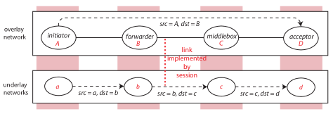
7.2.2 Virtual private networks
Strictly speaking, “virtual private networks” (VPNs) are not networks, but rather a technology for widening the geographic span of a private IP network such as an enterprise network. With VPN technology, an enterprise network is composed with other public and private IP networks in two ways simultaneously: (i) as usual, it is bridged with them, and (ii) it is layered on them, because some links of the enterprise network are implemented by sessions spanning other public and private IP networks. These relationships are illustrated by Figure 24.
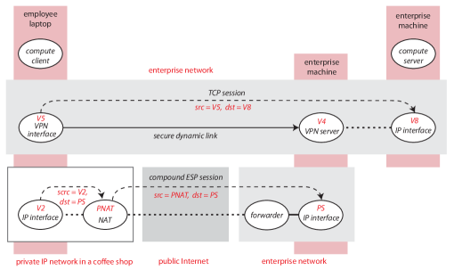
In the figure, there is a TCP session between an enterprise machine and an employee laptop currently located in a coffee shop. The enterprise-network member on the laptop is described as a “VPN interface,” because it is an IP interface plus VPN client. Before initiating the TCP session, it must first create a secure dynamic link to a VPN server in the enterprise network. To create the dynamic link, the laptop’s VPN interface requests that its IP interface make an ESP session (§4.3) to public IP name PS. The employee must also enter a password to authenticate his identity to the VPN server. The ESP session happens to be compound, because it goes through a Network Address Translator (similar to a proxy) in the coffee shop’s private IP network.
Viewed as an overlay network, the enterprise network uses VPN technology to allow a laptop in an insecure location to participate fully in the enterprise network. Most importantly, the VPN server assigns the laptop’s member the name V5 in the network’s private namespace. This name can be chosen according to the privileges the laptop’s owner has within the enterprise network. Consequently, traffic filters in the enterprise network can see from the source and destination fields of packets which policies should apply to the laptop’s sessions, and enforce them accordingly.
7.2.3 Overlays for default-reject filtering
In §5.1.3 we introduced default-reject filtering (filtering in which the default action on a packet is to drop it) as an interesting technique with limited applicability, because of the difficulty of finding precise filtering criteria. Default-reject filtering is similar in spirit to capabilities, introduced in §5.2.3, but it turned out that denial of capability is as much of a problem as denial of service. Several researchers have explored whether the properties of overlays can be exploited to make a success of default-reject filtering.
In both Mayday [1] and Secure Overlay Services (SOS) [30], the initiator of a session is authenticated, and session packets are not transmitted unless authentication succeeds. To understand these proposals, it is best to imagine the perspective of an access network that is trying to protect a Web server within the network from flooding attacks. The obvious problem with authentication at the edge of the access network is that the authenticators are a limited resource, easily overcome by denial-of-capability attacks. Mayday and SOS use overlays to extend the geographical span of the access network, enlisting allies all over the public Internet to perform authentication. The authenticators are the overlay ingress nodes in Figure 25. The idea is that there can be enough authenticators, dispersed widely enough, to resist flooding and denial-of-capability attacks. This is upstream filtering (§5.2.2) in the overlay network.
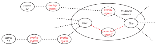
The general idea of Mayday and SOS is that packets of authenticated sessions travel to the protected target through the overlay as well as the Internet. Traffic filters near the protected target can distinguish overlay packets, and discard all other incoming packets. Details are given below.
These proposals make use of another overlay property in addition to flexible span: because an overlay is a network, it has its own routing. Overlay routing is used to vary and hide the paths of packets between ingress members and the target. This keeps attackers from flooding the paths to the target rather than the target itself. For instance, SOS uses a complex routing scheme, with long paths computed from distributed hash tables, for path secrecy. Other implications of overlay routing will be discussed further below.
In designing an overlay network for default-reject filtering, there are three important choices to be made. SOS makes specific choices, while the Mayday paper points out that there are other choices, and evaluates some combinations of them. We now explain the three choices.
Source authentication
This choice concerns how a session initiator finds an ingress member and authenticates itself to the overlay as a source of legimate packets. SOS is intended for use during an emergency situation, when networks are so congested that even benign ordinary traffic must be dropped. The members of SOS are hosted by a peer group of machines cooperating to provide emergency services. The only allowed packets to a given destination come from a few pre-configured sources used by emergency responders. So in SOS the source is itself an overlay member, i.e., it has special software. SOS source members know the Internet names of many ingress members, well-distributed so that they cannot all be overwhelmed by flooding attacks. It creates a secure link to an ingress member, using ESP with endpoint authentication.
Mayday emphasizes an authentication option that is architecturally more complex, but has broader applicability because the source need not be an overlay member (both Figures 25 and 26 depict this option). In this option packets from a source to target name are routed to some machine with an ingress member of the overlay. This can be accomplished by IP anycast, which will route packets from any source to the destination with name closest to them. The underlay IP interface accepts the TCP session and passes control to the ingress member, which can then authenticate the source by asking for a user name and password associated with the target service. If the source is authentic, the ingress member initiates a TCP session through the overlay to the target; these two TCP sessions then become two parts of a compound application session.
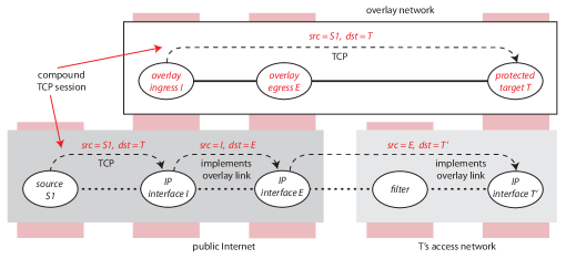
Note from Figure 26 that the target server receives as source name the underlay name of the initiator. This means that reverse packets, from the Web server to the initiator, do not travel through the overlay. Although the path of return packets is not shown in the figure, both SOS and Mayday work like this.
Lightweight authenticator
In addition to the overlay network, a potential target must be surrounded in the Internet underlay by a ring of ordinary traffic filters. These ordinary filters, such as firewalls, must have the capacity to handle flooding attacks, and must be configurable by overlay machines or by people administering the overlay.
Figure 26 is a session view of allowed access to protected target . The last overlay hop between an egress member of the overlay and the target is implemented by an underlay path that goes through a filter. The lightweight authenticator is the attribute of underlay packets from an egress member to the target that causes the traffic filter to recognize them as overlay packets and allow them to pass. The simplest lightweight authenticator is the IP name of the egress member (here ) in the source field of a packet; this is what SOS uses. Other authenticators proposed by Mayday include the destination port, destination name, and other header fields whose contents can be manipulated by the egress member.
The critical property of a lightweight authenticator is that it must be a secret—if attackers knew it, they could simply send underlay packets that match it. You might think that the destination name is the worst possible authenticator, but it can be a good one if the underlay name of the protected target is different from its overlay name, as shown in Figure 26, and if it can be changed easily and frequently by local control in the target’s access network.
Overlay routing
In addition to hiding whole packet paths, overlay routing keeps the identities of egress nodes secret, which is indispensable if the lightweight authenticator is the name of an egress node. SOS uses egress names as authenticators; this is safe because of its elaborate overlay routing.
Mayday takes the position that effective overlay routing can be much simpler, with options including no routing at all (ingress and egress nodes are the same), and singly-indirect routing (one hop between ingress and egress nodes, as in Figure 26). The Mayday paper reports on analysis showing that certain combinations of overlay routing and lightweight authenticator provide “best cases” for trade-offs among performance and security. For example, it says that designers who want moderate levels of both performance and security should use singly-indirect routing with any authenticator other than egress name.
7.2.4 Overlays for anonymity
In §7.1.2 we showed how proxies in transit networks can provide session-initiating users with privacy within their access networks and anonymity at the accepting endpoint. The weakness of this mechanism is that the user has no privacy whatsoever from the proxy. The purpose of the public service Tor [16, 47] is to add to the services above a high degree of privacy from the proxies. This section describes the second, current Tor design [16].
Tor is an overlay network whose infrastructure members reside on the machines of volunteers world-wide. These infrastructure members are fully connected by long-lived links, each of which is implemented by a TLS session in the public Internet. This covers two of the ways Tor makes use of overlay properties: its membership unites allies across the globe, and its links are long-lived and reused by many overlay sessions (which minimizes setup time and computational overhead).
An infrastructure member in Tor acts as a proxy within the overlay. Users also have Tor members on their machines. Each proxy has a public key, which it uses (along with a certificate) to authenticate itself when setting up links by means of TLS sessions.555In Tor terminology, a proxy is an “onion router” and a user member is an “onion proxy.” But Tor proxies do no routing, and user members do no proxying.
Tor is layered between application networks and the public Internet. Applications use the same interface to get TLS service from Tor as they would from the public Internet. User members query Tor directory servers to get lists of available proxies, each described by its public key, IP name, and policies.
To make a TLS session for an application (when there is no prior state in place), a Tor member first chooses a random route through several Tor proxies (this is why the proxies themselves do no routing). As with other overlay routing schemes, this varies and conceals packet paths. Next the user member creates a compound session in Tor that goes through the chosen proxies, as shown in Figure 27. The session protocol is the Tor “circuit” protocol, and each simple session is a Tor circuit with its own circuit identifier.
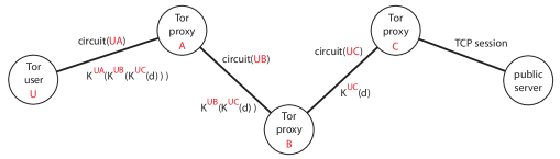
The important thing about circuits is that each one has a unique security association with the user member that created it. To make the compound session in Figure 27, the user first creates a simple session (circuit) to , and executes a key-exchange protocol with , so that each now knows a shared symmetric key . Next the user uses circuit(UA) to send to an extend command telling it to create a new circuit to proxy . Through the two associated circuits, and execute a key-exchange protocol, after which each has a shared key . Finally tells to extend the compound session by creating a new circuit to , with / key exchange. Once a compound session has been assembled in Tor, it can be used to carry many TLS application sessions. In the background, the compound session is reconfigured piece-by-piece about once a minute, to confuse adversarial observers who are analyzing traffic patterns.666Spies know that Tor sessions are deliberately concealed, so they have reason to analyze side-channels such as packet timing and sizes. These attacks can be successful in correlating packet streams coming into and out of Tor. Note that the adversarial observers can be Tor proxies, too.
Tor users use the security associations to conceal packet data from all except the last Tor proxy. The data transmitted on each circuit is multiply-encrypted as shown in the figure. When receives a packet from , it decrypts it before forwarding it to , but it cannot read the packet because it is doubly encrypted with keys and that are unknown to . For a similar reason, cannot read it either.
To understand the rest of the Tor design, it is necessary to consider TLS as a separate protocol embedded inside TCP. Tor has a second session protocol, the stream protocol, which is embedded in the circuit protocol. Figure 28 shows all the session protocols, with protocols above embedded in protocols below, used for a single TLS application session through Tor.
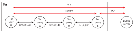
The stream protocol substitutes for TCP within Tor; there is a one-to-one correspondence between external TCP sessions and Tor streams, and TCP data is simply reformatted for streams. There are two reasons for using streams instead of TCP inside Tor: (i) if the data sent on Tor circuits were TCP packets, then proxy would see their source and destination fields in plaintext; (ii) the reliable, ordered packet delivery of TCP is not required within Tor, because all of its links are implemented by TLS, and already have these properties.
When has received enough stream packets to carry an HTTPS request with a domain name, it can complete the compound session end-to-end. It sends a TCP SYN packet with its own IP name as source and the IP name of the domain name as destination. After the TCP handshake, it continues converting data packets between the TCP and stream-protocol formats, and forwarding them in both directions. The TLS handshake between and the server goes end-to-end, so that can validate the server’s certificate, and so that even does not see plaintext packet data.
Tor is a complex network in its own right. We have seen that it has its own session protocols, compound sessions, and routing. It also has internal mechanisms for denial-of-service protection and congestion control. Rate-limiting can be managed on circuits or on streams.
Unfortunately the Tor design for privacy has one serious deficiency, which is the fact that the final acceptor of the TCP session can know that Tor is being used, because there are readily accessible lists of Tor nodes. Fraudsters, spammers, and other criminals are big users of Tor, along with law-abiding people in need of privacy. Consequently an increasing number of services are rejecting or otherwise discriminating against Tor users [31]. Tor protects the reputation of its volunteer machines by allowing them to restrict their exiting TCP sessions or refuse to be exit proxies. Some volunteers must shoulder this burden, however, or the service will not be available to those who really need it.
Although the Tor-exit problem appears to have no solution in today’s Internet, privacy is so valuable that some researchers propose to replace much of IP with the concepts of Tor [36]. If the use of Tor became much more widespread as this proposal argues it should, then the stigma of using Tor would fade away.
8 Conclusion
Modeling and security are tightly intertwined. Given a rigorous model of a network, security attacks, and defenses, we can reason rigorously or even formally that the defenses will prevent the attacks—or at least mitigate them. Where there are gaps in the model, i.e., possible real-world behaviors that the model does not describe, there are possible attacks against which the defenses are useless.
As networks have become increasingly important in most aspects of daily life, their complexity has grown in proportion, and the early models have become increasingly inadequate. In this tutorial we have used a new, compositional model, which emphasizes that there are many networks in an overall network architecture, each one being a microcosm of all the basic aspects of networking. Because all networks are similar in important ways, they can be modeled with common structures and common compositional interfaces. This modularity greatly expands the range of network behaviors that can be modeled without overwhelming complexity [58].
In this tutorial, the new model has enabled us to find a new and useful classification of security attacks, and to explain all common defenses by means of just four patterns. There is a clear relationship between the attack categories and the defense patterns, because the categories are based on which agents are the attackers, defenders, and potential victims, and some defenses are only available to some defenders.
The model has also helped us understand how the patterns interact with each other and with other aspects of networking, which is a dimension of security that has received little prior attention. Nevertheless it is essential, because networks must satisfy many goals simultaneouly, and designers cannot succeed if they are ignorant of the consequences of their decisions.
The modeling and defenses in this tutorial are obviously not complete, yet we believe that any progress toward organized thinking about network security will be helpful for building defenses and—ultimately—making verifiable claims about network security. It has been shown that real software can be made secure with modularity and verified components [33], and the world is sure to demand this level of assurance from more and more computer systems, including networks.
References
- [1] D. G. Andersen. Mayday: Distributed filtering for Internet services. In Proceedings of the 4th USENIX Symposium on Internet Technologies and Systems, 2003.
- [2] D. G. Andersen, H. Balakrishnan, N. Feamster, T. Koponen, D. Moon, and S. Shenker. Accountable Internet Protocol (AIP). In Proceedings of ACM SIGCOMM, 2008.
- [3] Arbor Networks. NETSCOUT Arbor’s 13th annual worldwide infrastructure security report. https://pages.arbornetworks.com/rs/082-KNA-087/images/13th_Worldwide_Infrastructure_Security_Report.pdf.
- [4] K. Argyraki and D. R. Cheriton. Active Internet traffic filtering: Real-time response to denial-of-service attacks. In Proceedings of the USENIX Annual Technical Conference, 2005.
- [5] K. Argyraki and D. R. Cheriton. Network capabilities: The good, the bad, and the ugly. In Proceedings of the 4th Workshop on Hot Topics in Networks, 2005.
- [6] D. Barrera, L. Chuat, A. Perrig, R. M. Reischuk, and P. Szalachowski. The SCION Internet architecture. Communications of the ACM, 60(6):56–65, June 2017.
- [7] R. Beckett, A. Gupta, R. Mahajan, and D. Walker. A general approach to network configuration verification. In Proceedings of ACM SIGCOMM, 2017.
- [8] R. Beckett, R. Mahajan, T. Millstein, J. Padhye, and D. Walker. Don’t mind the gap: Bridging network-wide objectives and device-level configurations. In Proceedings of ACM SIGCOMM, 2016.
- [9] M. S. Blumenthal and D. D. Clark. Rethinking the design of the Internet: The end-to-end arguments vs. the brave new world. ACM Transactions on Internet Technology, 1(1):70–109, August 2001.
- [10] R. Canetti. Universally Composable Security: A new paradigm for cryptographic protocols. https://eprint.iacr.org/2000/067.pdf, 2019. Accessed 15 October 2019.
- [11] M. Casado, M. J. Freedman, J. Pettit, J. Luo, N. McKeown, and S. Shenker. Ethane: Taking control of the enterprise. In Proceedings of SIGCOMM. ACM, August 2007.
- [12] Center for Applied Internet Data Analysis. Archipelago monitor statistics. https://www.caida.org/projects/ark/statistics/. Accessed 29 November 2019.
- [13] D. D. Clark. The design philosophy of the DARPA Internet protocols. In Proceedings of SIGCOMM. ACM, August 1988.
- [14] D. D. Clark. Designing an Internet. Information Policy Series, MIT Press, 2018.
- [15] D. D. Clark, J. Wroclawski, K. R. Sollins, and R. Braden. Tussle in cyberspace: Defining tomorrow’s Internet. IEEE/ACM Transactions on Networking, 13(3):462–475, June 2005.
- [16] R. Dingledine, N. Mathewson, and P. Syverson. Tor: The second-generation onion router. In Proceedings of the 13th USENIX Security Symposium, 2004.
- [17] Dyn analysis summary of Friday October 21 attack. https://dyn.com/blog/dyn-analysis-summary-of-friday-october-21-attack/. Accessed 10 November 2018.
- [18] A. Fogel, S. Fung, L. Pedrosa, M. Walraed-Sullivan, R. Govindan, R. Mahajan, and T. Millstein. A general approach to network configuration analysis. In Proceedings of the 12th USENIX Conference on Networked Systems Design and Implementation, 2015.
- [19] M. Georgiev, S. Iyengar, S. Jana, R. Anubhai, D. Boneh, and V. Shmatikov. The most dangerous code in the world: Validating SSL certificates in non-browser software. In ACM Conference on Computer and Communications Security, 2012.
- [20] S. Goldwasser, Y. Kalai, R. A. Popa, V. Vaikuntanathan, and N. Zeldovich. Reusable garbled circuits and succinct functional encryption. In Proceedings of Symposium on Theory of Computing. ACM, 2013.
- [21] T. Grandison and M. Sloman. A survey of trust in Internet applications. IEEE Communications Surveys and Tutorials, 3(4):2–16, 2000.
- [22] M. Handley. Why the Internet only just works. BT Technology Journal, 24(3):119–129, July 2006.
- [23] M. Handley, V. Paxson, and C. Kreibich. Network intrusion detection: Evasion, traffic normalization, and end-to-end protocol semantics. In Proceedings of the 10th USENIX Security Symposium, 2001.
- [24] How does TLS affect MQTT performance? https://www.hivemq.com/ blog/how-does-tls-affect-mqtt-performance/. Accessed 19 September 2018.
- [25] O. Honda, H. Ohsaki, M. Imase, M. Ishizuka, and J. Murayama. TCP over TCP: Effects of TCP tunneling on end-to-end throughput and latency. In Proceedings of SPIE, volume 6011, pages 138–146. International Society for Optical Engineering, 2005.
- [26] A. Houmansadr, G. T. K. Nguyen, M. Caesar, and N. Borisov. Cirripede: Circumvention infrastructure using router redirection with plausible deniability. In Proceedings of the ACM Conference on Computer and Communications Security, 2011.
- [27] ITU. Information Technology—Open Systems Interconnection—Basic Reference Model: The basic model. ITU-T Recommendation X.200, 1994.
- [28] J. Karlin, D. Ellard, A. W. Jackson, C. E. Jones, G. Lauer, D. P. Mankins, and W. T. Strayer. Decoy routing: Toward unblockable Internet communication. In Proceedings of the USENIX Workshop on Free and Open Communications on the Internet. USENIX, 2011.
- [29] P. Kazemian, M. Chang, H. Zeng, G. Varghese, N. McKeown, and S. Whyte. Real time network policy checking using Header Space Analysis. In Proceedings of the 10th USENIX Conference on Networked Systems Design and Implementation, 2013.
- [30] A. D. Keromytis, V. Misra, and D. Rubenstein. SOS: Secure Overlay Services. In Proceedings of SIGCOMM. ACM, August 2002.
- [31] S. Khattak, D. Fifield, S. Afroz, M. Javed, S. Sundaresan, V. Paxson, S. J. Murdoch, and D. McCoy. Do you see what I see? Differential treatment of anonymous users. In Proceedings of the Network and Distributed Security Symposium. Internet Society, 2016.
- [32] T. Kiravuo, M. Sarela, and J. Manner. A survey of Ethernet LAN security. IEEE Communications Surveys & Tutorials, 15(3):1477–1491, 2013.
- [33] G. Klein, J. Adronick, M. Fernandez, I. Kuz, T. Murray, and G. Heiser. Formally verified software in the real world. Communications of the ACM, 61(10):68–77, October 2018.
- [34] A. Langley et al. The QUIC transport protocol: Design and Internet-scale deployment. In Proceedings of ACM SIGCOMM, 2017.
- [35] N. Li, B. N. Grosof, and J. Feigenbaum. Delegation logic: A logic-based approach to distributed authorization. ACM Transactions on Information and System Security, 6(1):128–171, February 2003.
- [36] V. Liu, S. Han, A. Krishnamurthy, and T. Anderson. Tor instead of IP. In Proceedings of the 11th Workshop on Hot Topics in Networks, 2011.
- [37] N. P. Lopes, N. Bjorner, P. Godefroid, K. Jayaraman, and G. Varghese. Checking beliefs in dynamic networks. In Proceedings of the 12th USENIX Conference on Networked Systems Design and Implementation, 2015.
- [38] R. Mahajan, S. Bellovin, S. Floyd, J. Ioannidis, V. Paxson, and S. Shenker. Controlling high bandwidth aggregates in the network. Computer Communication Review, 32(3):62–73, July 2002.
- [39] B. Marczak, N. Weaver, J. Dalek, R. Ensafi, D. Fifield, S. McKune, A. Rey, J. Scott-Railton, R. Deibert, and V. Paxson. An analysis of China’s “Great Cannon”. In USENIX Workshop on Free and Open Communications on the Internet, August 2015.
- [40] C. Meadows. The NRL protocol analyzer: An overview. Journal of Logic Programming, 26(2):113–131, February 1996.
- [41] G. C. M. Moura, J. Heidemann, M. Muller, R. de O. Schmidt, and M. Davids. When the dike breaks: Dissecting DNS defenses during DDoS. In Proceedings of the ACM Internet Measurement Conference, 2018.
- [42] M. Nasr, A. Houmansadr, and A. Mazumdar. Compressive traffic analysis: A new paradigm for scalable traffic analysis. In ACM Conference on Computer and Communications Security, 2017.
- [43] D. Naylor, A. Finamore, I. Leontiadis, Y. Grunenberger, M. Mellia, M. Munafo, K. Papagiannaki, and P. Steenkiste. The cost of the ‘S’ in HTTPS. In Proceedings of ACM CoNEXT, 2014.
- [44] D. Naylor, R. Li, C. Gkantsidis, , T. Karagiannis, and P. Steenkiste. And then there were more: Secure communication for more than two parties. In Proceedings of ACM CoNEXT, 2017.
- [45] D. Naylor, K. Schomp, M. Varvello, I. Leontiadis, J. Blackburn, D. Lopez, K. Papagiannaki, P. R. Rodriguez, and P. Steenkiste. Multi-context TLS (mcTLS): Enabling secure in-network functionality in TLS. In Proceedings of ACM SIGCOMM, 2015.
- [46] C. Raiciu, C. Paasch, S. Barre, A. Ford, M. Honda, F. Duchene, O. Bonaventure, and M. Handley. How hard can it be? designing and implementing a deployable Multipath TCP. In Networked Systems Design and Implementation, 2012.
- [47] M. G. Reed, P. F. Syverson, and D. M. Goldschlag. Anonymous connections and onion routing. IEEE Journal on Selected Areas in Communications, 16(4):482–494, May 1998.
- [48] S. Savage, D. Wetherall, A. Karlin, and T. Anderson. Practical network support for IP traceback. In Proceedings of SIGCOMM. ACM, 2000.
- [49] P. Schmitt, A. Edmundson, A. Mankin, and N. Feamster. Oblivious DNS: Practical privacy for DNS queries. arXiv:1806.00276v2, 2018.
- [50] Y. Sheffer, R. Holz, and P. Saint-Andre. Summarizing known attacks on Transport Layer Security (TLS) and Datagram TLS (DTLS). Internet Engineering Task Force Request for Comments 7457, 2015.
- [51] J. Sherry, C. Lan, R. A. Popa, and S. Ratnasamy. BlindBox: Deep packet inspection over encrypted traffic. In Proceedings of SIGCOMM. ACM, 2015.
- [52] R. Sommer and V. Paxson. Outside the closed world: On using machine learning for network intrusion detection. In Proceedings of the IEEE Symposium on Security and Privacy, 2010.
- [53] R. Spreitzer, V. Moonsamy, T. Korak, and S. Mangard. Systematic classification of side-channel attacks: A case study for mobile devices. IEEE Communications Surveys & Tutorials, 20(1):465–488, 2018.
- [54] J. Vertesi. My experiment opting out of big data made me look like a criminal. https://time.com/83200/privacy-internet-big-data-opt-out. Accessed 15 October 2019.
- [55] E. Wustrow, S. Wolchok, I. Goldberg, and J. A. Halderman. Telex: Anticensorship in the network infrastructure. In Proceedings of the 20th USENIX Security Symposium, 2011.
- [56] A. Yaar, A. Perrig, and D. Song. Pi: A path identification mechanism to defend against DDoS attacks. In Proceedings of the Symposium on Security and Privacy. IEEE, 2003.
- [57] X. Yang, D. Wetherall, and T. Anderson. A DoS-limiting network architecture. In Proceedings of SIGCOMM. ACM, August 2005.
- [58] P. Zave and J. Rexford. The compositional architecture of the Internet. Communications of the ACM, 62(3):78–87, March 2019.
- [59] L. Zhang, A. Afanasyev, J. Burke, and V. Jacobson. Named data networking. ACM SIGCOMM Computer Communication Review, 44(3):66–73, July 2014.