Skyrmion Crystal and Phase Transition in Magneto-Ferroelectric Superlattices: Dzyaloshinskii-Moriya Interaction in a Frustrated Model
Abstract
The formation of a skyrmion crystal and its phase transition are studied taking into account the Dzyaloshinskii-Moriya (DM) interaction at the interface between a ferroelectric layer and a magnetic layer
in a superlattice. The frustration is introduced in both magnetic and ferroelectric
films. The films have the simple cubic lattice structure. Spins inside magnetic layers are Heisenberg spins interacting with each other via nearest-neighbor (NN) exchange and next-nearest-neighbor (NNN) exchange . Polarizations in the ferroelectric layers are assumed to be of Ising type with NN and NNN interactions and . At the magnetoelectric interface, a DM interaction between spins and polarizations is supposed.
The spin configuration in the ground state is calculated by the steepest descent method. In an applied magnetic field perpendicular to the layers, we show that the formation of skyrmions at the magnetoelectric interface is strongly enhanced by the frustration brought about by the NNN antiferromagnetic interactions and . Various physical quantities at finite temperatures are obtained by Monte Carlo simulations. We show the critical temperature, the order parameters of magnetic and ferroelectric layers as functions of the interface DM coupling, the applied magnetic field and and .
The phase transition to the disordered phase is studied in details.
Keywords: kyrmions; phase transition; frustration; superlattice; magneto-ferroelectric coupling; Dzyaloshinskii-Moriya interaction; model; Monte Carlo simulation.
I Introduction
The localized topological spin-textures called ”magnetic skyrmions” currently attract intensive researches due to their fundamental properties and practical applicationsbogdanov1989thermodynamically ; yu2010real ; yu2011near ; heinze2011spontaneous ; romming2013writing ; rosch2013skyrmions . Indeed, skyrmions are promising structures for future digital technologiesleonov2016chiral ; moreau2016additive ; soumyanarayanan2017tunable ; dupe2016engineering ; muller2016edge ; rosch2017spintronics ; shen2019spin ; fert2013skyrmions ; bessarab2019stability . In addition, next-generation spintronic devices can be based on metastable isolated skyrmions guided along magnetic stripesfert2013skyrmions ; tomasello2014strategy ; koshibae2015memory ; kang2016voltage . Skyrmions have been experimentally observed in many materials, in particular in magnetic materials zhang2017skyrmion ; muhlbauer2009skyrmion ; yu2010real ; heinze2011spontaneous ; romming2013writing ; du2015edge ; jiang2015blowing ; leonov2016chiral ; leonov2016properties ; woo2016observation ; jiang2017direct ; litzius2017skyrmion ; woo2017spin , multiferroic materials seki2012observation , ferroelectric materials nahas2015discovery , and semiconductors kezsmarki2015neel . Skyrmions have been seen also in helimagnets muhlbauer2009skyrmion ; yu2010real . Under an applied magnetic field, it has been shown that the helical spin configuration is transformed into a skyrmion lattice with a triangular structure DiepSD . In a strong magnetic field the spin ordering is ferromagnetic (FM) but there exist isolated stable skyrmions as topological defects butenko2010stabilization ; rossler2011chiral .
Real magnetic materials have complicated interactions and there are large families of frustrated systems such as the heavy lanthanides metals (holmium, terbium and dysprosium) zverev2014magnetic ; zverev2015magnetic , helical MnSi stishov2007magnetic . Other interesting properties of skyrmions in magnetically frustrated systems have also been investigatedleonov2017edge ; lin2016ginzburg ; hayami2016bubble ; hayami2016vortices ; lin2016magnetic ; batista2016frustration ; yuan2017skyrmions ; rozsa2016skyrmions ; rozsa2017formation ; sutcliffe2017skyrmion ; DiepSD . Multiferroics and superlattices of multiferroics (for example and ) currently attract many research activities on these materials because of the coexistence of ferroelectric and magnetic orderings. A large number of investigations was devoted to the non-uniform states in magneto-ferroelectric superlattices both theoretically sharafullin2019dzyaloshinskii and experimentallyzheng2004multiferroic ; bibes2008multiferroics ; mathur2008materials ; nan1994magnetoelectric ; sergienko2006role ; udalov2018coulomb ; ortiz2014monte . In Ref. janssen1994dynamics ; janssen1982microscopic Janssen et al. have proposed a new model for the interaction between polarizations and spins in magneto-ferroelectric superlattices. Using this model, the dynamics and configuration of domain walls for the unidimensional case have been simulated. Li et al. li2002monte have proposed an algorithm based on the Monte Carlo method for a two-dimensional (2D) lattice. Recently, magneto-ferroelectric superlattices draw much of attention as magneto-electric (ME) materials. This is due to intrinsic magneto-electric effects stemming from the spin-orbit interaction sergienko2006role as well as from the spin charge-orbital coupling pyatakov2018magnetoelectricity . It has been shown that surface ME effects appear due to the charge and spin accumulation maruyama2009large ; udalov2018coulomb . The enhancement of magnetoelectric effect due to phase separation was shown in Ref. alberca2015phase . Many microscopic interaction mechanisms for different materials have been suggested. Among these, we can mention the lone skyrmion-pair mechanism karthik2012site , the ferroelectricity in manganitesgarcia2014geometric , the multiferroicity induced by the spiral spin orderingxiang2011general , the off-center shifts in geometrically frustrated magnetsbalents2010spin . In Ref. pei2017frustration it was shown that magnetic frustration results in a phase competition, which is the origin of the magnetoelectric response. A possible experimental realization of an isolated skyrmion as well as a skyrmion lattice has been suggested gobel2017antiferromagnetic . In Ref. bessarab2019stability the 2D Heisenberg exchange model with Dzyaloshinskii-Moriya (DM) interaction is used to study the lifetime of antiferromagnetic skyrmions. Spin waves and skyrmions in magnetoelectric superlattices with a DM interface coupling have been studied sharafullin2019dzyaloshinskii . Yadav et al. yadav2016observation have produced complex topologies of electrical polarizations, namely nanometer-scale vortex-antivortex structure, using the competition between charge, orbital and lattice degrees of freedom in superlattices of alternate lead titanate and strontium titanate films. They showed that the vortex state is the low-energy state for various superlattice periods. In Ref. zhang2017skyrmion , the authors have explored skyrmions and antiskyrmions in a 2D frustrated ferromagnetic system with competing exchange interactions based on the classical Heisenberg model on a simple square lattice lin2016ginzburg with the dipole-dipole interaction, neglected in previous works leonov2015multiply ; leonov2017edge . Dipole-dipole interaction has been shown to create the frustration in systems of skyrmions. The interface-induced skyrmions have been investigated. The superstructures are obviously the best to create interactions of skyrmions on different interfaces causing very particular dynamics compared to interactions between skyrmions of the same interface. We can mention a theoretical study of two skyrmions on two-layer systems koshibae2017theory using micromagnetic modeling, and an analysis based on the Thiele equation. It has been found that there is a reaction between them such as the collision and a bound state formation. The dynamics of these skyrmions depends on the sign of DM interaction, and the number of two skyrmions is well described by the Thiele equation. Another interesting aspect is a colossal spin-transfer-torque effect of bound skyrmion pair revealed in antiferromagnetically coupled bilayer systems. Note that the study of the current-induced motion using the Thiele equation was carried in a skyrmion lattice through two models of the pinning potentialmartinez2016topological . Shi-Zeng Lin et al Shi-ZengLin have studied the dynamics of skyrmions in chiral magnets in the presence of a spin polarized current. They have also shown that skyrmions can be created by increasing the current in the magnetic spiral state. Numerical simulations of Landau-Lifshitz-Gilbert equation have been performed in Ref. J-Iwasaki which reveals a remarkably robust and universal current-velocity relation of the skyrmion motion driven by the spin-transfer-torque. This is unaffected by either impurities or non adiabatic effect, in sharp contrast to the case of domain wall or spin helix.
Note that in Ref. sharafullin2019dzyaloshinskii we have studied effects of Dzyaloshinskii-Moriya (DM) magneto-ferroelectric coupling in a superlattice formed by ”unfrustrated” magnetic and ferroelectric films. In zero field, we have shown that the GS spin configuration is periodically non collinear. By the use of a Green’s function technique, we have calculated the spin-wave spectrum in a monolayer and in a bilayer sandwiched between ferroelectric films. We have shown in particular that the DM interaction strongly affects the long-wavelength spin-wave mode. In a magnetic field applied in the direction perpendicular to the layers, we have shown that skyrmions are arranged to form a crystalline structure at the interface.
In this paper we study a superlattice composed of alternate ”frustrated” magnetic films and ”frustrated” ferroelectric films. The frustration due to competing interactions has been extensively investigated during the last four decades. The reader is referred to Ref. DiepFSS for reviews on theories, simulations and experiments on various frustrated systems. Our present aim is to investigate the effect of the frustration in the presence of the DM interaction at the magnetoelectric interface. It turns out that the frustration gives rise to an enhancement of skyrmions created by the DM interaction in a field applied perpendicularly to the films. Monte Carlo simulations are carried out to study the skyrmion phase transition in the superlattice as functions of the frustration strength.
The paper is presented as follows. In section II we describe our model and show how to determine the ground-state spin structure. The skyrmion crystal is shown with varying frustration parameters. Section III is devoted to the presentation of the Monte Carlo results for the phase transition in the system as a function of the frustration, in the presence of the interface DM coupling. These results show that the skyrmion crystalline structure is stable up to a transition temperature . Concluding remarks are given in section IV.
II Model and Skyrmion Crystal
II.1 Model
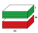
The superlattice we study here is shown in Fig. 1a. It is composed of magnetic and ferroelectric films with the simple cubic lattice. The Hamiltonian of this magneto-ferroelectric superlattice is given by:
| (1) |
where and indicate the magnetic and ferroelectric parts, respectively. denotes Hamiltonian of magnetoelectric interaction at the interface of two adjacent films. We are interested in the frustrated regime. Therefore we consider the following magnetic Hamiltonian with the Heisenberg spin model
| (2) |
where is the spin occupying the i-th lattice site, denotes the magnetic field applied along the axis and the magnetic interaction between two spins and . We shall take into account both the nearest neighbors (NN) interaction, denoted by , and the next-nearest neighbor (NNN) interaction denoted by . We consider to be the same everywhere in the magnetic film. To introduce the frustration we shall consider , namely antiferromagnetic interaction, the same everywhere. The interactions between spins and polarizations at the interface are given below.
Before introducing the DM interface interaction, let us emphasize that the bulk model on the simple cubic lattice has been studied with Heisenberg spins DiepPinettes and the Ising model DiepTai where and are both antiferromagnetic (). The critical value above which the bipartite antiferromagnetic ordering changes into a frustrated ordering where a line is with spins up, and its neighboring lines are with spins down. In the case of (ferro), and , it is easy to show that the critical value where the ferromagnetic becomes antiferromagnetic is . Below this value, the antiferromagnetic ordering replaces the ferromagnetic ordering.
For the ferroelectric film, we assume that electric polarizations are of Ising model of magnitude 1, pointing in the direction. The Hamiltonian reads
| (3) |
where is the polarization on the i-th lattice site, the interaction parameter between polarizations at sites and . Similar to the magnetic subsystem we will take the same for all NN pairs, and for NNN pairs.
We know that the DM interaction is written as
| (4) |
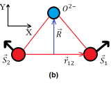
where is the spin at the i-th magnetic site, while denotes the Dzyaloshinskii-Moriya vector which is defined as where is the displacement of the ligand ion (oxygen) and the unit vector along the axis connecting and (see Fig. 1b). One then has
| (5) |
We define thus
| (6) |
where is a constant, the unit vector on the axis, and .
For the magnetoelectric interaction at the interface, we choose the interface Hamiltonian following Ref. sharafullin2019dzyaloshinskii :
| (7) |
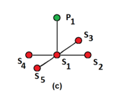
where is the polarization at the site of the ferroelectric interface layer, while and belong to the interface magnetic layer (see Fig. 1c). In this expression is defined as the DM vector which is along the axis, given by Eq. (6). When summing the neighboring pairs , attention should be paid on the signs of and (see example in Ref. sharafullin2019dzyaloshinskii ).
Hereafter, we suppose independent of .
Since is in the direction, i. e. the DM vector is in the direction, in the absence of an applied field the spins in the magnetic layers will lie in the plane to minimize the interface interaction energy, according to Eq. (7).
In Eq. (7), the magnetoelectric interaction favors a non-collinear spin structure in competition with the exchange interactions and which favor collinear (ferro and antiferro) spin configurations. In ferroelectric layers, only collinear, ferro- or antiferromagnetic ordering, is possible because of the assumed Ising model for the polarizations. Historical demonstration, the DM interaction was supposed small with respect to the exchange terms in the Hamiltonian. However, in superlattices the magnetoelectric interaction is necessary to create non-collinear spin ordering. It has been shown that Rashba spin-orbit coupling can lead to a strong DM interaction at the interface YangH2018 ; ManchonA2015 , where the broken inversion symmetry at the interface can change the magnetic states. The DM interaction has been identified as a key ingredient in the creation, stabilization of skyrmions and chiral domain walls.
II.2 Ground state
From Eq. (7) we see that the interface interaction is minimum when and lie in the interface plane and perpendicular to each other in the absence of exchange interactions. When the exchange interactions are turned on, the collinear configuration will compete with the DM perpendicular configuration. This results in a non-collinear configuration as will be shown below.
We note that when the magnetic film has more than one layer, the angle between NN spins in each magnetic layer is different. The determination of the angles is analytically difficult. We have to recourse to the numerical method called ”steepest descent method” to minimize the energy to get the ground state (GS): we calculate the local field acting on a spin and align it in the direction of the local field. We go to another spin and do the same thing until all spins are visited. We repeat the operation many times until the total energy becomes minimum.
In the simulations, a sample size has been used, with the linear lateral size , and thickness , where (: magnetic layer’s thickness, : ferroelectric layer’s thickness). We use the periodic boundary conditions in the plane.
For simplicity, we take exchange parameters between NN spins and NN polarizations equal to 1, namely , for the simulations. We investigate the effects of the interaction parameters and . We note that the steepest descent method calculates the GS down to the value . For values lower than this, the DM interaction is so strong that the spin-spin angle tends to so that magnetic exchange terms are zero.
Now we consider a case with the frustrated regime with , namely above the critical value -0.5 as mentioned above.
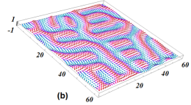
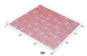
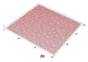
The spin configuration in the case where is shown in Fig. 2 for the interface magnetic layer. We observe here a stripe phase with long islands and domain walls. The inside magnetic layers have the same texture.
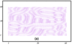
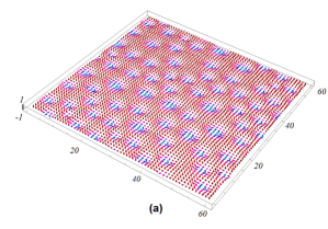
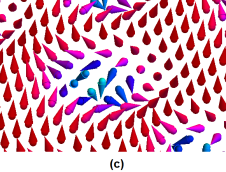
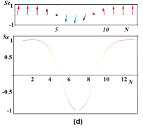
When is increased, we observe the skyrmion crystal as seen in Fig. 3: the GS configuration of the interface and beneath magnetic layers obtained for , with and external magnetic field . A zoom of a skyrmion shown in Fig. 3c and the -components across a skyrmion shown in Fig. 3d indicate that the skyrmion is of Bloch type.
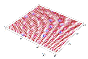
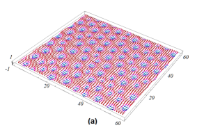
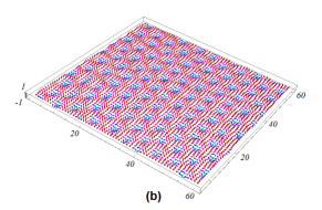
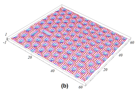
At this field strength , if we increase the frustration, for example , then the skyrmion structure is enhanced: we can observe a clear skyrmion crystal structure not only in the interface layer but also in the interior layers. This is shown in Fig. 4 where the interface and the second layer are displayed.
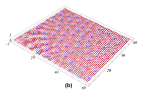
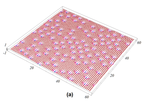
The highest value of frustration where the skyrmion structure can be observed is when close to the critical value -0.5. We show this case in Fig. 5: the GS configuration of the interface (a) and second (interior) (b) magnetic layers are presented. Other parameters are the same as in the previous figures, namely and . We can observe a clear skyrmion crystal structure in the whole magnetic layers, not only near the interface layer. Unlike the case where we do not take into account the interaction between sharafullin2019dzyaloshinskii , in the present case where the frustration is very strong we see that a large number of skyrmions are distributed over the whole magnetic layers with a certain periodicity close to a perfect crystal.
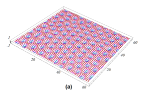
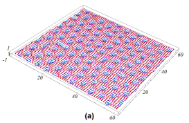
Though we take the same value for and in the figures shown above, it is obvious that only the magnetic frustration is important for the skyrmion structure. The ferroelectric frustration affects only the stability of the polarizations at the interface. As long as does not exceed -0.5, the skyrmions are not affected by . We show in Fig. 6 the GS configuration of the interface and the second magnetic layers for and (other parameters: , ). We see that the skyrmion structure is not different from the case () shown in Fig. 4.
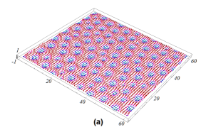
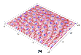
Fig. 7 shows the GS configuration of the interface and second (interior) magnetic layers for ( and ) which is not visibly different from the case () shown in Fig. 5. We conclude here that when the magnetic frustration is strong enough, the ferroelectric frustration does not affect the skyrmion structure.
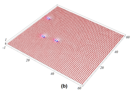
Now, if the magnetic frustration is not strong enough, the ferroelectric frustration plays an important role: Fig. 8a shows the GS configuration of the interface magnetic layer for (, ) and Fig. 8a shows the case of (, ). We see that skyrmions disappear when . Comparing this to the case (, ) where skyrmions are clearly formed, we conclude that while magnetic frustration enhances the formation of skyrmions, the ferroelectric frustration in the weak magnetic frustration tends to suppress skyrmions. The mechanism of these parameters when acting together seems to be very complicated.
Let us show now the effect of . In the case of zero frustration, skyrmions disappear with an external field larger than sharafullin2019dzyaloshinskii . In the case when we take into account the negative interaction between neighbors, the skyrmion structure is stable with an external field up to (see Fig 9). The spins are almost aligned in the direction of the field.
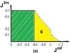
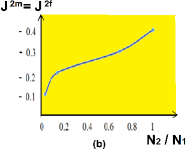
The phase diagram in plane, for the case , , is shown in Fig. 10a. We can see that in region skyrmions are not formed at any value of . In region skyrmions are formed at non-zero values of . The smaller the larger values of should be for the formation of skyrmions at the interface. With skyrmions are formed without frustration at zero values of . When we introduce frustration in the magnetic layers at magneto-ferroelectric interaction , skyrmions form a perfect crystalline structure. Figure 10b shows the dependence of the ratio of the number of skyrmions on the interior layer to that on the interface layer . We see that as the frustration becomes stronger the ratio tends to 1.
Let us discuss about some theoretical observations of skyrmions in frustrated magnets leonov2017edge ; lin2016ginzburg ; hayami2016bubble ; hayami2016vortices ; lin2016magnetic ; batista2016frustration ; yuan2017skyrmions ; sutcliffe2017skyrmion ; DiepSD . Each of these works used a different model, so the comparison is impossible. However, all shows very similar skyrmion textures. For experiments, a lot of observations have been made in various magnetic materials zhang2017skyrmion ; muhlbauer2009skyrmion ; yu2010real ; heinze2011spontaneous ; romming2013writing ; du2015edge ; jiang2015blowing ; leonov2016chiral ; leonov2016properties ; woo2016observation ; jiang2017direct ; litzius2017skyrmion ; woo2017spin , in multiferroic materials seki2012observation , in ferroelectric materials nahas2015discovery , in semiconductors kezsmarki2015neel and in helimagnets muhlbauer2009skyrmion ; yu2010real . Here again, each real material corresponds to a particular microscopic mechanism, the comparison is not simple. However, one observes many similar topological textures.
III Skyrmion Phase Transition
The magnetic transition is driven by the competition between , the DM interaction (namely ), the field and the magnetic texture (skyrmions). The stronger and/or , the higher the transition temperature of the skyrmion structure. As mentioned above strong DM interaction helps stabilize the skyrmion crystal YangH2018 ; ManchonA2015 at the superlattice interface. We use a strong as in the previous section.
We use the Metropolis algorithm Landau09 ; Brooks11 to simulate the system at . We perform calculations for systems with different sizes where varied from 40 to 100 and the thickness varied from 2 to 16. It should be noted that changing the lateral size of does not affect the results on skyrmions shown in the article. But the influence of the total thickness of the magnetic and ferroelectric layers is very significant: with an increase in the thickness of the magnetic and ferroelectric layers from to 8, skyrmions are formed only near the interface, not on layers far inside. In most calculations, we used and . With this thickness, skyrmions are observed in the two interior layers as seen in the previous section. Usually, we discard Monte Carlo steps (MCS) per spin for equilibrating the system and average physical quantities over the next MCS/spin. Such long MC times are needed since it has been tested for the skyrmion crystal similar to that of the present model DiepSD .
For the ferroelectric layers, the order parameter of layer is given by
| (8) |
where indicates the thermal average.
For the magnetic layers where the spin configuration is not collinear, the definition of an order parameter is not easy. One way to do is to heat the system from a selected GS configuration. At a given , we compare the actual spin configuration observed at the time with its GS. The comparison is made by projecting that configuration on the GS. The order parameter of layer can be thus calculated by
| (9) |
where is the i-th spin at the time , at , and denotes its orientation at . We see that is close to 1 at very low where each spin is close to its orientation in the GS. At high where every spin strongly fluctuates, becomes zero.
Note that is defined in a similar way as the Edwards-Anderson (EA) order parameter in spin glasses Mezard . The EA order parameter is calculated by taking the time average of each spin. When it is frozen at low , its time average is not zero. At high , it strongly fluctuates with time so that its time average is zero. The EA order parameter is just the sum of the squares of each spin average. It expresses thus the degree of freezing but does not express the kind of ordering.
Note that if the system makes a global rotation during the simulation then for a long-time average. To check this, the most efficient way to do is to calculate the relaxation time to obtain properties at the infinite time, in the same spirit as the finite-size scaling used to calculate properties at the infinite system size. We have calculated the relaxation time of the 2D skyrmion crystal DiepSD using the order parameter defined by Eq. (9). We have found that skyrmions need more than MCS/spin to relax to equilibrium and the order parameter follows a stretched exponential law as in SG for .
Another way to check the stability of the skyrmion crystal is to count numerically the topological charges around each skyrmionKoibuchi-Diep2019 . If there is a phase transition, the charge number, which plays the role of an order parameter, evolves with and goes to zero at the phase transition.
The total order parameters and are the sum of the layer order parameters, namely and .
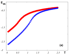
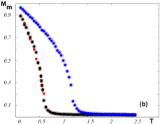
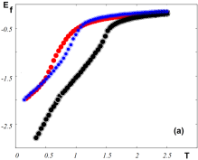
We display now in Fig.11 the magnetic energy and the magnetic order parameter vs in an external magnetic field, for various sets of NNN interaction. Note that the phase transition occurs at the energy curvature changes, namely at the maximum of the specific heat. The red curve in Fig.11a is for both sets , . The change of curvature takes place at . It means that the ferroelectric frustration does not affect the magnetic skyrmion transition at such a strong magnetic frustration . For , namely no magnetic frustration, the transition takes place at a much higher temperature .
At this stage, we note that the above results are shown in the dimensionless unit: energy in unit of and temperature in unit of . Our results can be used for materials with different . For example, if experimentally one observes that the skyrmion phase transition occurs at K, we can calculate the effective exchange using for example the mean-field equation
| (10) | |||||
| (11) | |||||
| (12) |
where (simple cubic lattice), (spin magnitude) and Joules/Kelvin have been used. is a combination of , and . Knowing the GS, we can deduce these interactions. We can calculate then the energy in unit of Joule by multiplying the value of in Fig. 11a by the value of . Unfortunately, there is at the time being no experimental energy measurement for comparison.
The magnetic order parameters shown in Fig. 11b confirm the skyrmion transition temperatures seen by the curvature change of the energy in Fig.11a.
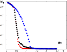
We show in Fig. 12a the ferroelectric energy and ferroelectric order parameters for the same sets of frustration parameters: (), (, ), (, ). As seen, the first and second sets where the magnetic frustration is strong give respectively , 0.90. It means that the ferroelectric frustration which does not affect the skyrmion transition, strongly affects the ferroelectric transition. While, the third set with no magnetic frustration () gives the transition at . Figure 12b shows the ferroelectric order parameters for the three sets of NNN interactions shown in Fig. 12a. These curves confirm the transition temperatures given above.
IV Conclusion
We have studied in this paper the effect of the NNN interactions in both magnetic and ferroelectric layers of a magneto-ferroelectric superlattice. A Dzyaloshinskii-Moriya (DM) interaction was assumed for the magneto-ferroelectric interface coupling.
We found the formation of a skyrmion crystal in the GS under an applied magnetic field in a large region of parameters in the space (. As expected, the magnetic frustration enhances the creation of skyrmions while the ferroelectric frustration when strong enough destabilizes skyrmions if the magnetic frustration is weak.
We have studied the phase transition of the skyrmion crystal by the use of Monte Carlo method. Skyrmions have been shown to be stable at finite temperatures. While the magnetic frustration helps enhance the creation of skyrmions, it reduces the transition temperature considerably.
The existence of very stable skyrmions confined at the magneto-ferroelectric interface at finite is very interesting and may have potential applications in spintronics. Many applications using skyrmions have been mentioned in the Introduction. As a last remark, let us mention that the present magneto-ferroelectric superlattice model can be used in the case of magnetic monolayer or bilayer to study the dynamics of the skyrmions driven by a spin-polarized current or by a spin-transfer torque. Due to the small thickness, the skyrmions created by the interface are well confined as in 2D. Our model is therefore suitable for creating skyrmion pinning by using an electric field acting on the ferroelectric polarizations. This subject is our future investigation.
References
- (1) A. N. Bogdanov, D. Yablonskii, Thermodynamically stable vortices in magnetically ordered crystals. the mixed state of magnets, Zh. Eksp. Teor. Fiz 95 (1) (1989) 178.
- (2) X. Yu, Y. Onose, N. Kanazawa, J. Park, J. Han, Y. Matsui, N. Nagaosa, Y. Tokura, Real-space observation of a two-dimensional skyrmion crystal, Nature 465 (7300) (2010) 901.
- (3) X. Yu, N. Kanazawa, Y. Onose, K. Kimoto, W. Zhang, S. Ishiwata, Y. Matsui, Y. Tokura, Near room-temperature formation of a skyrmion crystal in thin-films of the helimagnet fege, Nature materials 10 (2) (2011) 106.
- (4) S. Heinze, K. Von Bergmann, M. Menzel, J. Brede, A. Kubetzka, R. Wiesendanger, G. Bihlmayer, S. Blügel, Spontaneous atomic-scale magnetic skyrmion lattice in two dimensions, Nature Physics 7 (9) (2011) 713.
- (5) N. Romming, C. Hanneken, M. Menzel, J. E. Bickel, B. Wolter, K. von Bergmann, A. Kubetzka, R. Wiesendanger, Writing and deleting single magnetic skyrmions, Science 341 (6146) (2013) 636–639.
- (6) A. Rosch, Skyrmions: Moving with the current, Nature nanotechnology 8 (3) (2013) 160.
- (7) A. Leonov, Y. Togawa, T. Monchesky, A. Bogdanov, J. Kishine, Y. Kousaka, M. Miyagawa, T. Koyama, J. Akimitsu, T. Koyama, et al., Chiral surface twists and skyrmion stability in nanolayers of cubic helimagnets, Physical review letters 117 (8) (2016) 087202.
- (8) C. Moreau-Luchaire, C. Moutafis, N. Reyren, J. Sampaio, C. Vaz, N. Van Horne, K. Bouzehouane, K. Garcia, C. Deranlot, P. Warnicke, et al., Additive interfacial chiral interaction in multilayers for stabilization of small individual skyrmions at room temperature, Nature nanotechnology 11 (5) (2016) 444.
- (9) A. Soumyanarayanan, M. Raju, A. G. Oyarce, A. K. Tan, M.-Y. Im, A. P. Petrović, P. Ho, K. Khoo, M. Tran, C. Gan, et al., Tunable room-temperature magnetic skyrmions in ir/fe/co/pt multilayers, Nature materials 16 (9) (2017) 898.
- (10) B. Dupé, G. Bihlmayer, M. Böttcher, S. Blügel, S. Heinze, Engineering skyrmions in transition-metal multilayers for spintronics, Nature communications 7 (2016) 11779.
- (11) J. Müller, A. Rosch, M. Garst, Edge instabilities and skyrmion creation in magnetic layers, New Journal of Physics 18 (6) (2016) 065006.
- (12) A. Rosch, Spintronics: Electric control of skyrmions, Nature nanotechnology 12 (2) (2017) 103.
- (13) L. Shen, J. Xia, G. Zhao, X. Zhang, M. Ezawa, O. A. Tretiakov, X. Liu, Y. Zhou, Spin torque nano-oscillators based on antiferromagnetic skyrmions, Applied Physics Letters 114 (4) (2019) 042402.
- (14) A. Fert, V. Cros, J. Sampaio, Skyrmions on the track, Nature nanotechnology 8 (3) (2013) 152.
- (15) P. Bessarab, D. Yudin, D. Gulevich, P. Wadley, M. Titov, O. A. Tretiakov, Stability and lifetime of antiferromagnetic skyrmions, Physical Review B 99 (14) (2019) 140411.
- (16) R. Tomasello, E. Martinez, R. Zivieri, L. Torres, M. Carpentieri, G. Finocchio, A strategy for the design of skyrmion racetrack memories, Scientific reports 4 (2014) 6784.
- (17) W. Koshibae, Y. Kaneko, J. Iwasaki, M. Kawasaki, Y. Tokura, N. Nagaosa, Memory functions of magnetic skyrmions, Japanese Journal of Applied Physics 54 (5) (2015) 053001.
- (18) W. Kang, Y. Huang, C. Zheng, W. Lv, N. Lei, Y. Zhang, X. Zhang, Y. Zhou, W. Zhao, Voltage controlled magnetic skyrmion motion for racetrack memory, Scientific reports 6 (2016) 23164.
- (19) X. Zhang, J. Xia, Y. Zhou, X. Liu, H. Zhang, M. Ezawa, Skyrmion dynamics in a frustrated ferromagnetic film and current-induced helicity locking-unlocking transition, Nature communications 8 (1) (2017) 1717.
- (20) S. Mühlbauer, B. Binz, F. Jonietz, C. Pfleiderer, A. Rosch, A. Neubauer, R. Georgii, P. Böni, Skyrmion lattice in a chiral magnet, Science 323 (5916) (2009) 915–919.
- (21) H. Du, R. Che, L. Kong, X. Zhao, C. Jin, C. Wang, J. Yang, W. Ning, R. Li, C. Jin, et al., Edge-mediated skyrmion chain and its collective dynamics in a confined geometry, Nature communications 6 (2015) 8504.
- (22) W. Jiang, P. Upadhyaya, W. Zhang, G. Yu, M. B. Jungfleisch, F. Y. Fradin, J. E. Pearson, Y. Tserkovnyak, K. L. Wang, O. Heinonen, et al., Blowing magnetic skyrmion bubbles, Science 349 (6245) (2015) 283–286.
- (23) A. Leonov, T. Monchesky, N. Romming, A. Kubetzka, A. Bogdanov, R. Wiesendanger, The properties of isolated chiral skyrmions in thin magnetic films, New Journal of Physics 18 (6) (2016) 065003.
- (24) S. Woo, K. Litzius, B. Krüger, M.-Y. Im, L. Caretta, K. Richter, M. Mann, A. Krone, R. M. Reeve, M. Weigand, et al., Observation of room-temperature magnetic skyrmions and their current-driven dynamics in ultrathin metallic ferromagnets, Nature materials 15 (5) (2016) 501.
- (25) W. Jiang, X. Zhang, G. Yu, W. Zhang, X. Wang, M. B. Jungfleisch, J. E. Pearson, X. Cheng, O. Heinonen, K. L. Wang, et al., Direct observation of the skyrmion hall effect, Nature Physics 13 (2) (2017) 162.
- (26) K. Litzius, I. Lemesh, B. Krüger, P. Bassirian, L. Caretta, K. Richter, F. Büttner, K. Sato, O. A. Tretiakov, J. Förster, et al., Skyrmion hall effect revealed by direct time-resolved x-ray microscopy, Nature Physics 13 (2) (2017) 170.
- (27) S. Woo, K. M. Song, H.-S. Han, M.-S. Jung, M.-Y. Im, K.-S. Lee, K. S. Song, P. Fischer, J.-I. Hong, J. W. Choi, et al., Spin-orbit torque-driven skyrmion dynamics revealed by time-resolved x-ray microscopy, Nature communications 8 (2017) 15573.
- (28) S. Seki, X. Yu, S. Ishiwata, Y. Tokura, Observation of skyrmions in a multiferroic material, Science 336 (6078) (2012) 198–201.
- (29) Y. Nahas, S. Prokhorenko, L. Louis, Z. Gui, I. Kornev, L. Bellaiche, Discovery of stable skyrmionic state in ferroelectric nanocomposites, Nature communications 6 (2015) 8542.
- (30) I. Kézsmárki, S. Bordács, P. Milde, E. Neuber, L. Eng, J. White, H. M. Rønnow, C. Dewhurst, M. Mochizuki, K. Yanai, et al., Néel-type skyrmion lattice with confined orientation in the polar magnetic semiconductor gav 4 s 8, Nature materials 14 (11) (2015) 1116.
- (31) S. El Hog, A. Bailly-Reyre, H. T. Diep, Stability and phase transition of skyrmion crystals generated by dzyaloshinskii-moriya interaction, J. Magnetism and Magnetic Materials 455 (2018) 32.
- (32) A. Butenko, A. Leonov, U. Rößler, A. Bogdanov, Stabilization of skyrmion textures by uniaxial distortions in noncentrosymmetric cubic helimagnets, Physical Review B 82 (5) (2010) 052403.
- (33) U. K. Rößler, A. A. Leonov, A. N. Bogdanov, Chiral skyrmionic matter in non-centrosymmetric magnets, Journal of Physics: Conference Series 303 (1) (2011) 012105.
- (34) V. Zverev, A. Tishin, A. Chernyshov, Y. Mudryk, K. A. Gschneidner Jr, V. K. Pecharsky, Magnetic and magnetothermal properties and the magnetic phase diagram of high purity single crystalline terbium along the easy magnetization direction, Journal of Physics: Condensed Matter 26 (6) (2014) 066001.
- (35) V. Zverev, A. Tishin, Z. Min, Y. Mudryk, K. Gschneidner Jr, V. Pecharsky, Magnetic and magnetothermal properties, and the magnetic phase diagram of single-crystal holmium along the easy magnetization direction, Journal of Physics: Condensed Matter 27 (14) (2015) 146002.
- (36) S. M. Stishov, A. E. Petrova, S. Khasanov, G. K. Panova, A. A. Shikov, J. C. Lashley, D. Wu, T. A. Lograsso, Magnetic phase transition in the itinerant helimagnet mnsi: Thermodynamic and transport properties, Physical Review B 76 (5) (2007) 052405.
- (37) A. Leonov, M. Mostovoy, Edge states and skyrmion dynamics in nanostripes of frustrated magnets, Nature communications 8 (2017) 14394.
- (38) S.-Z. Lin, S. Hayami, Ginzburg-landau theory for skyrmions in inversion-symmetric magnets with competing interactions, Physical Review B 93 (6) (2016) 064430.
- (39) S. Hayami, S.-Z. Lin, C. D. Batista, Bubble and skyrmion crystals in frustrated magnets with easy-axis anisotropy, Physical Review B 93 (18) (2016) 184413.
- (40) S. Hayami, S.-Z. Lin, Y. Kamiya, C. D. Batista, Vortices, skyrmions, and chirality waves in frustrated mott insulators with a quenched periodic array of impurities, Physical Review B 94 (17) (2016) 174420.
- (41) S.-Z. Lin, S. Hayami, C. D. Batista, Magnetic vortex induced by nonmagnetic impurity in frustrated magnets, Physical review letters 116 (18) (2016) 187202.
- (42) C. D. Batista, S.-Z. Lin, S. Hayami, Y. Kamiya, Frustration and chiral orderings in correlated electron systems, Reports on Progress in Physics 79 (8) (2016) 084504.
- (43) H. Yuan, O. Gomonay, M. Kläui, Skyrmions and multisublattice helical states in a frustrated chiral magnet, Physical Review B 96 (13) (2017) 134415.
- (44) L. Rózsa, A. Deák, E. Simon, R. Yanes, L. Udvardi, L. Szunyogh, U. Nowak, Skyrmions with attractive interactions in an ultrathin magnetic film, Physical review letters 117 (15) (2016) 157205.
- (45) L. Rózsa, K. Palotás, A. Deák, E. Simon, R. Yanes, L. Udvardi, L. Szunyogh, U. Nowak, Formation and stability of metastable skyrmionic spin structures with various topologies in an ultrathin film, Physical Review B 95 (9) (2017) 094423.
- (46) P. Sutcliffe, Skyrmion knots in frustrated magnets, Physical review letters 118 (24) (2017) 247203.
- (47) I. F. Sharafullin, M. K. Kharrasov, H. T. Diep, Dzyaloshinskii-moriya interaction in magnetoferroelectric superlattices: Spin waves and skyrmions, Physical Review B 99 (21) (2019) 214420.
- (48) H. Zheng, J. Wang, S. Lofland, Z. Ma, L. Mohaddes-Ardabili, T. Zhao, L. Salamanca-Riba, S. Shinde, S. Ogale, F. Bai, et al., Multiferroic batio3-cofe2o4 nanostructures, Science 303 (5658) (2004) 661–663.
- (49) M. Bibes, A. Barthélémy, Multiferroics: Towards a magnetoelectric memory, Nature materials 7 (6) (2008) 425.
- (50) N. Mathur, Materials science: A desirable wind up, Nature 454 (7204) (2008) 591.
- (51) C.-W. Nan, Magnetoelectric effect in composites of piezoelectric and piezomagnetic phases, Physical Review B 50 (9) (1994) 6082.
- (52) I. A. Sergienko, E. Dagotto, Role of the dzyaloshinskii-moriya interaction in multiferroic perovskites, Physical Review B 73 (9) (2006) 094434.
- (53) O. Udalov, I. Beloborodov, The coulomb based magneto-electric coupling in multiferroic tunnel junctions and granular multiferroics, AIP Advances 8 (5) (2018) 055810.
- (54) H. Ortiz-Álvarez, C. Bedoya-Hincapié, E. Restrepo-Parra, Monte carlo simulation of charge mediated magnetoelectricity in multiferroic bilayers, Physica B: Condensed Matter 454 (2014) 235–239.
- (55) T. Janssen, Dynamics of (anti) ferromagnetic/electric domain walls, Ferroelectrics 162 (1) (1994) 265–273.
- (56) T. Janssen, J. Tjon, Microscopic model for incommensurate crystal phases, Physical Review B 25 (6) (1982) 3767.
- (57) Q. Li, X. Chen, X. Gao, J.-M. Liu, Z. Liu, Monte-carlo study on phase transitions of ferroelectromagnets, Ferroelectrics 279 (1) (2002) 67–81.
- (58) A. Pyatakov, Magnetoelectricity goes local: From bulk multiferroic crystals to ferroelectricity localized on magnetic topological textures, Physica B: Condensed Matter 542 (2018) 59–62.
- (59) T. Maruyama, Y. Shiota, T. Nozaki, K. Ohta, N. Toda, M. Mizuguchi, A. Tulapurkar, T. Shinjo, M. Shiraishi, S. Mizukami, et al., Large voltage-induced magnetic anisotropy change in a few atomic layers of iron, Nature nanotechnology 4 (3) (2009) 158.
- (60) A. Alberca, C. Munuera, J. Azpeitia, B. Kirby, N. Nemes, A. Perez-Muñoz, J. Tornos, F. Mompean, C. Leon, J. Santamaria, et al., Phase separation enhanced magneto-electric coupling in la 0.7 ca 0.3 mno 3/batio 3 ultra-thin films, Scientific reports 5 (2015) 17926.
- (61) T. Karthik, T. D. Rao, A. Srinivas, S. Asthana, A-site cation disorder and size variance effects on the physical properties of multiferroic bi0. 9re0. 1feo3 ceramics (re= gd3+, tb3+, dy3+), arXiv preprint arXiv:1206.5606.
- (62) A. C. Garcia-Castro, N. A. Spaldin, A. Romero, E. Bousquet, Geometric ferroelectricity in fluoroperovskites, Physical Review B 89 (10) (2014) 104107.
- (63) H. Xiang, E. Kan, Y. Zhang, M.-H. Whangbo, X. Gong, General theory for the ferroelectric polarization induced by spin-spiral order, Physical review letters 107 (15) (2011) 157202.
- (64) L. Balents, Spin liquids in frustrated magnets, nature 464 (7286) (2010) 199–208.
- (65) H. Pei, S. Guo, L. Ren, C. Chen, B. Luo, X. Dong, K. Jin, R. Ren, H. M. Zeeshan, The frustration-induced ferroelectricity of a manganite tricolor superlattice with artificially broken symmetry, Scientific reports 7 (1) (2017) 6201.
- (66) B. Göbel, A. Mook, J. Henk, I. Mertig, Antiferromagnetic skyrmion crystals: Generation, topological hall, and topological spin hall effect, Physical Review B 96 (6) (2017) 060406.
- (67) A. Yadav, C. Nelson, S. Hsu, Z. Hong, J. Clarkson, C. Schlepütz, A. Damodaran, P. Shafer, E. Arenholz, L. Dedon, et al., Observation of polar vortices in oxide superlattices, Nature 530 (7589) (2016) 198.
- (68) A. Leonov, M. Mostovoy, Multiply periodic states and isolated skyrmions in an anisotropic frustrated magnet, Nature communications 6 (2015) 8275.
- (69) W. Koshibae, N. Nagaosa, Theory of skyrmions in bilayer systems, Scientific reports 7 (2017) 42645.
- (70) J. Martinez, M. Jalil, Topological dynamics and current-induced motion in a skyrmion lattice, New Journal of Physics 18 (3) (2016) 033008.
- (71) S.-Z. Lin, C. Reichhardt, C. D. Batista, A. Saxena, Driven skyrmions and dynamical transitions in chiral magnets, Phys. Rev. Lett. 110.
- (72) J. J. Iwasaki, M. Mochizuki, N. Nagaosa, Universal current-velocity relation of skyrmion motion in chiral magnets, Nat. Commun. 4.
- (73) H. T. Diep, Frustrated Spin Systems, World Scientific, 2013.
- (74) C. Pinettes, H. T. Diep, Phase transition and phase diagram of the j1-j2 heisenberg model on a simple cubic lattice, J. Appl. Phys. 83 (1998) 6317.
- (75) D.-T. Hoang, Y. Magnin, H. T. Diep, Spin resistivity in the frustrated j1-j2 model, Modern Phys. Letters 25 (2011) 937.
- (76) H. Yang, G. Chen, A. A. C. Cotta, A. T. N’ Diaye, S. A. Nikolaev, E. A. Soares, W. A. A. Macedo, K. Liu, A. K. Schmid, A. Fert, M. Chshiev, Significant dzyaloshinskii-moriya interaction at graphene-ferromagnet interfaces due to the rashba effect, Nat. Mater. 17 (2018) 605.
- (77) A. Manchon, H. C. Koo, J. Nitta, S. Frolov, R. Duine, New perspectives for rashba spin-orbit coupling, Nat. Mater. 14 (2015) 871.
- (78) D. P. Landau, K. Binder, A Guide to Monte Carlo Simulations in Statistical Physics , Cambridge University Press, London, 2009.
- (79) S. Brooks, A. Gelman, S. L. Jones, X.-L. Meng, Handbook of Markov Chain Monte Carlo, CRC Press, 2011.
- (80) M. Mézard, M. Parisi, M. Virasoro, Spin Glass Theory and Beyond An Introduction to the Replica Method and Its Applications , World Scientific, 1986.
- (81) S. El Hog, F. Kato, H. Koibuchi, H. T. Diep, Skyrmions on 2d elastic surfaces with fixed boundary frame, J. Mag. Mag. Mat. (accepted, to appear). arXiv:1910.01760.