Study of Switched Max-Link Relay Selection for Cooperative Multiple-Antenna Systems
Abstract
In this work, we present a switched relaying framework for multiple-input multiple-output (MIMO) relay systems where a source node may transmit directly to a destination node or aided by relays. We also investigate relay selection techniques for the proposed switched relaying framework, whose relays are equipped with buffers. In particular, we develop a novel relay selection protocol based on switching and the selection of the best link, denoted as Switched Max-Link. We then propose the Maximum Minimum Distance (MMD) relay selection criterion for MIMO systems, which is based on the optimal Maximum Likelihood (ML) principle and can provide significant performance gains over other criteria, along with algorithms that are incorporated into the proposed Switched Max-Link protocol. An analysis of the proposed Switched Max-Link protocol and the MMD relay selection criterion in terms of computational cost, pairwise error probability, sum-rate and average delay is carried out. Simulations show that Switched Max-Link using the MMD criterion outperforms previous works in terms of sum-rate, pairwise error probability, average delay and bit error rate.
Index Terms:
Cooperative communications, Relay-selection, Max-Link, Maximum Likelihood criterion, MIMOI INTRODUCTION
In wireless networks, signal fading caused by multipath propagation is a channel propagation phenomenon that can be mitigated through the use of cooperative diversity[1, 2, 3]. In cooperative communications with multiple relays, where a number of relays help a source to transmit data packets to a destination, by receiving, decoding and forwarding these packets, relay selection schemes are key because of their high performance [4, 5, 6]. As cooperative communication can improve the throughput and extend the coverage of wireless communications systems, the task of relay selection serves as a building block to realize it. In this context, relay schemes have been included in recent/future wireless standards such as Long Term Evolution (LTE) Advanced [7, 8] and 5G standards [9].
I-A Prior and Related Work
In conventional relaying, using half duplex (HD) and decode-and-forward protocols, transmission is often organized in a prefixed schedule with two successive time slots. In the first time slot, the relay receives and decodes the data transmitted from the source, and in the second time slot the relay forwards the decoded data to the destination. Single relay selection schemes use the same relay for reception and transmission, and cannot simultaneously exploit the best available source-relay () and relay-destination () channels. The most common schemes are bottleneck based and maximum harmonic mean based best relay selection (BRS) [4].
The performance of relaying schemes can be improved if the link with the highest power is used in each time slot. This can be achieved via a buffer-aided relaying protocol, where the relay can accumulate packets in its buffer prior to transmission. The use of buffers provides an improved performance and extra degrees of freedom for system design [7, 10]. However, it suffers from additional delay that must be well managed for delay-sensitive applications. Buffer-aided relaying protocols require not only the acquisition of channel state information (CSI), but control of the buffer status. Applications of buffer-aided relaying are: vehicular, cellular, and sensor networks [7].
In Max-Max Relay Selection (MMRS) [4], in the first time slot, the relay selected for reception can store the received packets in its buffer and forward them at a later time when selected for transmission. In the second time slot, the relay selected for transmission can transmit the first packet in the queue of its buffer, which was received from the source earlier. MMRS assumes infinite buffer sizes. However, considering finite buffer sizes, the buffer of a relay becomes empty if the channel conditions are such that it is selected repeatedly for transmission (and not for reception) or full if it is selected repeatedly for reception (and not for transmission). To overcome this limitation, in [4] a hybrid relay selection (HRS) scheme, which is a combination of BRS and MMRS, was proposed.
Although MMRS and HRS improve the throughput and/or SNR gain as compared to BRS, their diversity gain is limited to the number of relays . This can be improved by combining adaptive link selection with MMRS, which results in the Max-Link [11] protocol. The main idea of Max-Link is to select in each time slot the strongest link among all the available and links (i.e., among links) for transmission [12]. For independent and identically distributed (i.i.d.) links and no delay constraints, Max-Link achieves a diversity gain of , which is twice the diversity gain of BRS and MMRS.
Max-Link has been extended in [13] to account for direct source-destination () connectivity, which provides resiliency in low transmit SNR conditions [12]. In [14, 15, 16, 17, 18, 19, 20], buffer-aided relay selection protocols were shown to improve the Max-Link performance by reducing the average packet delay, ensuring a good diversity gain, and/or achieving full diversity gain with a smaller buffer size as compared to Max-Link. In [14], the outage performance and the average packet delay of a relay system that exploits buffer-aided max-link relay selection are analyzed. In [15], a study of the average packet delay of a buffer-aided scheme that selects a relay node based on both the channel quality and the buffer state of the relay nodes was performed. In [16], the relay associated with the largest weight is selected among the qualified source-relay and relay-destination links, where each link is assigned with a weight related to the buffer status. In [17], motivated by the Max-Link and the Max-Max protocols, a hybrid buffer-aided cooperative protocol that attains the benefits of reliability and reduced packet delay is reported. In [18], a delay and diversity-aware buffer-aided relay selection policy that reduces the average delay and obtains a good diversity gain is proposed. In [19], a relay selection scheme that seeks to maintain the states of the buffers by balancing the arrival and departure rates at each relay’s buffer has been reported. In [20], the best relay node is selected as the link with the highest channel gain among the links within a priority class. In summary, the previous schemes (MMRS, HRS and Max-Link) only use buffer-aided relay selection for cooperative single-antenna systems.
More recently, buffer-aided relay selection protocols for cooperative multiple-antenna systems have been studied. In [21], a virtual full-duplex (FD) buffer-aided relaying to recover the loss of multiplexing gain caused by HD relaying in a multiple relay network through joint opportunistic relay selection (RS) and beamforming (BF), is presented. Moreover, in [22], a cooperative network with a buffer-aided multi-antenna source, multiple HD buffer-aided relays and a single destination is presented to recover the multiplexing loss of the network.
I-B Contributions
In this work, we develop a switched relaying framework extended for MIMO relay systems that considers direct or cooperative transmissions with Maximum Likelihood (ML) detection and a Switched Max-Link protocol for cooperative MIMO systems, with non reciprocal channels, which selects the best links among relay nodes and whose preliminary results were reported in [23] and then further detailed in [26]. We then consider the novel MMD relay selection criterion [23], which is based on the optimal ML principle and the Pairwise Error Probability (PEP) [23, 24, 25], and the existing Quadratic Norm (QN) criterion and devise relay selection algorithms for Switched Max-Link. An analysis of the proposed scheme in terms of PEP, sum-rate, average delay and computational cost is also carried out. Simulations illustrate the excellent performance of the proposed framework, the proposed Switched Max-Link protocol and the MMD-based relay selection algorithm as compared to previously reported approaches. The main contributions of this work can be summarized as:
-
1.
A switched relaying framework extended for MIMO relay systems that considers direct or cooperative transmissions with ML detection;
-
2.
The Switched Max-Link protocol for cooperative MIMO relay systems;
-
3.
The MMD criterion for MIMO relay systems, along with a relay selection algorithm;
-
4.
An analysis of the proposed Switched Max-Link scheme with the MMD relay selection criterion in terms of PEP, sum-rate, average delay and computational cost.
Table I shows the description of the main symbols adopted in this work.
| Symbols | Description |
|---|---|
| Destination node | |
| MMD metric | |
| Minimum distance | |
| Minimum value of the PEP argument | |
| Distances between the constellation symbols | |
| Average delay of the MMD-Max-Link protocol | |
| Average delay of the Switched Max-Link protocol | |
| Average queue length | |
| Energy transmitted from | |
| Energy transmitted from | |
| Average throughput of a relay | |
| Matrix of links | |
| Matrix of links | |
| Submatrix of links | |
| Matrix of links | |
| Submatrix of links | |
| Size of the buffer (in packets) | |
| Queue length | |
| Number of antennas at and | |
| Number of antennas at the relays | |
| Number or relays | |
| Number of constellation symbols | |
| Power spectral density of the AWGN | |
| AWGN at | |
| AWGN at | |
| Probability of operating in the Max-Link mode | |
| QN metric | |
| Covariance matrix of the transmitted symbols (for ) | |
| Covariance matrix of the transmitted symbols (for ) | |
| Covariance matrix of the transmitted symbols (for ) | |
| Relay selected for reception | |
| Relay selected for transmission | |
| Sum-Rate | |
| Source node | |
| Switch of the Switched Max-Link protocol | |
| Number of sets of antennas at the relays | |
| Vector of transmitted symbols | |
| Estimate of the vector of transmitted symbols | |
| Number of calculations of the MMD metric | |
| Received vector of symbols (for links) | |
| Received vector of symbols (for links) | |
| Received vector of symbols (for links) | |
| Average data rate |
This paper is structured as follows. Section II describes the system model and the main assumptions made. Section III details the proposed Switched Max-Link protocol with the MMD relay selection criterion whereas Section IV analyzes it. Section V illustrates and discusses the numerical results whereas Section VI gives the concluding remarks.
II System Description
We consider a multiple-antenna relay network with one source node, , one destination node, , and half-duplex decode-and-forward (DF) relays, ,…,. The and nodes have antennas for transmission and reception, respectively, and each relay antennas, where . All the antennas are used for reception () and a set of antennas is selected among to be used for transmission (). Thus, this configuration forms a spatial multiplexing network, in which the channel matrices are square or formed by multiple square submatrices. Each relay is equipped with a buffer, whose size is packets and the transmission is organized in time slots [4]. This configuration is considered for simplicity. The considered system is shown in Fig. 1.

II-A Assumptions
In cooperative transmissions two time slots are needed to transmit data packets from to , so the energy transmitted in direct transmissions (from to ) is twice the energy transmitted in cooperative transmissions, from to the relay selected for reception or from the relay selected for transmission to (), . For this reason, the energy transmitted from each antenna in cooperative transmissions equals and the energy transmitted from each antenna in direct transmissions equals . We consider that the channel coefficients are modeled by mutually independent zero mean complex Gaussian random variables. Moreover, we assume that the transmission is organized in data packets and the channels are constant for the duration of one time slot and vary independently from one time slot to the next. The information about the order of the data packets is contained in the preamble of each packet, so the original order is restored at . Other information such as signaling for CSI estimation are also inserted in the preamble of the packet. We consider perfect and imperfect CSI. A distributed implementation can reduce signaling overheads and reduce the impact of outdated CSI. Furthermore, we assume that the relays do not communicate with each other. We also assume that is the central node, being responsible for deciding whether or a relay should transmit in a given time slot . The central node has access to the channel and the buffer state information, so it may run the algorithm in each time slot and select the relay for transmission or reception through a feedback channel. This assumption can be ensured by an appropriate signalling that provides global CSI at [11]. Furthermore, we assume that has no CSI and each relay has only information about its channels and buffer status.
II-B System Model
The proposed system can operate in each time slot in two modes: "Direct Transmission" (DT) or "Max-Link". Thus, depending on the relay selection metrics (explained in Section III), the system may operate in each time slot with three options:
a) DT mode: transmits packets directly to ;
b) Max-Link- mode: transmits packets to ;
c) Max-Link- mode: transmits packets to .
If the relay selection algorithm decides to operate in the DT mode, the received signal from the to is organized in an vector given by
| (1) |
where represents the vector formed by symbols sent by , represents the matrix of links and denotes the zero mean additive white complex Gaussian noise (AWGN) at . Assuming synchronization and perfect CSI, at we employ the ML receiver which yields
| (2) |
where represents each possible vector formed by symbols. Thus, the ML receiver computes the vector of transmitted symbols which is the optimal solution. As an example, if we have BPSK (number of constellation symbols ), unit power symbols and , the estimated vector of transmitted symbols may be , , or . Other suboptimal detection techniques could be considered in future work [34, 35, 36, 37, 38, 39, 68, 41, 42, 43, 44, 45, 46, 47, 48].
Otherwise, if the relay selection algorithm decides to operate in the Max-Link- mode, the received signal from to is organized in an vector given by
| (3) |
where represents the matrix of links and represents the AWGN at . Note that is formed by square submatrices of dimensions as given by
| (4) |
Assuming synchronization and perfect CSI, at we employ the ML receiver [5]:
| (5) |
Moreover, if the relay selection algorithm decides to operate in the Max-Link- mode, the signal transmitted from to is structured in an vector given by
| (6) |
where is the vector formed by previously decoded symbols in the relay selected for reception and stored in its buffer and now transmitted by and is an matrix of links. Alternatively, a designer can consider precoding techniques [49, 50, 51, 52, 53, 54, 55, 56, 62] to help mitigate interference rather than open loop transmission. Note that is selected among submatrices of dimension contained in as given by
| (7) |
At , we also resort to the ML receiver which computes
| (8) |
Considering imperfect CSI, the estimated channel matrix is assumed, instead of in (2), (5) and (8): a channel error matrix is added to the channel matrix (, or ) and we focus on the case where errors decay as for some constant [27]. Thus, the variance of the coefficients is given by (), in the case of or , and , in the case of . As an example, in the case of , the estimated channel matrix is given by . Channel and parameter estimation [57, 58, 59, 60, 61, 62, 63, 64, 65, 66, 67, 68] techniques could be considered in future work in order to develop algorithms for this particular setting.
III Principles of Switched Max-Link Relay Selection Based on MMD
In this section, we detail the proposed Switched Max-Link relay selection protocol.
III-A Principles of Switched Max-Link Relay Selection
The system presented in Fig. 1 is equipped with the proposed Switched Max-Link relay selection protocol, that in each time slot may operate in two possible modes ("DT" or "Max-Link"), with three options:
a) work in DT mode: sends packets directly to ;
b) work in Max-Link- mode: sends packets to and these packets are stored in its buffer;
c) work in Max-Link- mode: forwards packets from its buffer to .
The proposed Switched Max-Link protocol uses the MMD relay selection criterion. As the scheme proposed in [28], the proposed MMD relay selection criterion is based on the ML principle. However, the metrics calculated by MMD are different from those of the scheme in [28], which leads to considerably better performance. MMD is also based on the worst case of the PEP and chooses the relay associated with the largest minimum Euclidian distance. So, it requires the distance between the possible vectors of transmitted symbols. The MMD-based relay selection algorithm, in the Max-Link- mode, chooses the relay and the associated channel matrix with the largest minimum distance as given by
| (9) |
where , , , and represent each possible vector formed by symbols and . The metric is calculated for each of the (combination of in ) possibilities, for each submatrix , and is the smallest of these values, for each . Thus, the selected matrix has the largest value.
Moreover, the MMD-based relay selection algorithm, in the Max-Link- mode, chooses the relay and the associated channel matrix with the largest minimum distance as given by
| (10) |
where and . Note that the submatrix associated with the largest value is selected among submatrices of dimension contained in . Table II shows the Switched Max-Link pseudo-code and the following subsections explain how this protocol works.
| 1: Calculate the metrics , of each submatrix of |
| ; |
| 2: Find the minimum distance - |
| 3: Calculate the metrics , of each submatrix of |
| ; |
| 4: Find the minimum distance - |
| 5: Find the largest minimum distance - |
| 6: Compute the expected values and |
| 7: Perform ordering on and |
| 8: Find the maximum minimum distance |
| ; |
| 9: Calculate the metrics |
| 10: Find the minimum distance - |
| 11: Select the transmission mode |
| ; |
| † Note that is a parameter that works as a |
| switch. When the scheme operates only in the Max-Link- |
| ( or ) mode (MMD-Max-Link protocol). Moreover, when |
| the scheme operates in the Max-Link-( or ) |
| or DT mode (Switched-Max-Link protocol). |
III-B Calculation of relay selection metric
In the first step we calculate the metrics related to the channels of each submatrix of each relay , in Max-Link mode:
| (11) |
where , , and represent each possible vector formed by symbols and . This metric is calculated for each of the (combination of in ) possibilities. As an example, if and , we have possibilities. Then, we store the smallest metric (), for being critical (a bottleneck) in terms of performance, and thus each relay will have a minimum distance associated with its channels. In the second step we calculate the metrics related to the channels of each submatrix of each relay :
| (12) |
where . This metric is also calculated for each of the possibilities. Then, we store the minimum distance (), and thus each submatrix will have a minimum distance associated with its channels. In the third step, we find the largest minimum distance , and thus each relay will have its best channel submatrix which is associated with this distance:
| (13) |
In the fourth step, after calculating the metrics and for each of the relays, as described previously, we compute the expected values of and and adjust the values to balance the number of time slots selected for Max-Link- and Max-Link- modes:
| (14) |
Then, we perform ordering and select the largest value of these distances:
| (15) |
Therefore, we select the relay that is associated with , considering its buffer status. This relay will be selected for reception (if its buffer is not full) or transmission (if its buffer is not empty), depending on this metric is associated with the or channels, respectively. Otherwise, the algorithm checks if the next maximum minimum distance and the associated relay meet the necessary requirements related to the buffer status.
III-C Calculation of the metric for direct transmission
In this step we calculate the metric related to the channels for the DT mode:
| (16) |
where . This metric is calculated for each
of the possibilities. Then, we store the minimum distance ().
Considering imperfect CSI, the estimated channel matrix is assumed, instead of in (11), (12) and (16).
After finding and , we compare these parameters and select the transmission mode that is equal to
where , , and is a parameter that works as a switch. In [23], assuming symmetric channels and applications without critical delay constraints, the switch is equal to one. If we consider asymmetric channels and the need for a short average delay, we select an that takes for granted that the protocol achieves a good BER and average delay performance. If is equal to zero, the protocol is selected to operate only in the Max-Link mode and we do not have the possibility of a direct connectivity and, consequently, we have another scheme called "MMD-Max-Link". Otherwise, when we increase , the number of time slots in which the protocol is selected to operate in the DT mode increases.
IV Analysis of MMD: Impact on Relay Selection, PEP, Complexity, Sum-rate and Average Delay
In this section, we first analyze the proposed MMD and the existing QN relay selection criteria. We compare the PEP and the computational complexity of the MMD criterion versus the QN criterion. We then derive expressions to compute the sum-rate and the average delay of the Swiched Max-Link protocol.
IV-A Impact of the MMD and QN criteria on relay selection
The metrics (, and ) are calculated in (11), (12) and (16), for each of the possibilities. However, in the following, we will show that it is not necessary to calculate all these possibilities. The total number of calculations of the metric , needed by the MMD criterion, depends on the number of antennas at and and the number of antennas at each relay. Furthermore, it depends on the constellation (BPSK, QPSK, 16-QAM…), specifically on the number of different distances between the constellation symbols. For the MMD criterion to compute the metric , it is necessary to consider the absolute value of the distances between the constellation symbols (). If we have BPSK and unit power symbols, . Otherwise, if we have QPSK, there are different values for : , and .
We may consider that the channel matrix represents , or . In the case of and , if and are different from each other in just one symbol in position , we have:
| (17) |
If and are different from each other in two symbols in positions and , we have:
| (18) |
where the indices and may be different from each other.
If and are different from each other in symbols, we have:
| (19) |
where the indices and may be different from each other.
We can simplify the equations, making , where =, for and , or = 2, for . We know that the PEP considers the error event when is transmitted and the detector computes an incorrect (where ), based on the received symbol [29, 30]. If we consider , then and, consequently, and the PEP is given by
| (20) |
where is the power spectrum density of the AWGN. The MMD criterion, by maximizing the value of the minimum distance , also maximizes the minimum value of the PEP argument (PEP worst case). The PEP argument is related to the sum of the powers of the coefficients of each column (or the combination of two or more columns by addition or subtraction) of the matrix . Moreover, when , is formed by multiple square submatrices , and the maximization of the minimum distances related to also implies the maximization of the minimum value of the PEP argument.
As an example, if we have BPSK and unit power symbols () and (), for each matrix ( or ), we have to calculate 4 different values for :
| (21) |
If we have the direct transmission option, by considering the matrix , we also have to calculate the same expressions described in (21), multiplied by 2. Note that these examples were considered by adopting BPSK, but other constellations (QPSK, 16-QAM…) can be adopted.
The MMD metric is based on the minimum Euclidian distances between the possible vectors of transmitted symbols. In contrast, in the QN criterion, that is based only on the total power of these links (as the traditional Max-Link), the metric is related to the quadratic norm (the sum of the powers of all the coefficients) of each matrix :
| (22) |
Thus, the QN criterion selects the channel matrix , as given by
| (23) |
where and .
The MMD criterion, differently from the QN criterion, takes into account the minimum distances related to in (17), in (LABEL:eq:12) and in (LABEL:eq:13), to select :
| (24) |
where and .
The advantage of the MMD algorithm as compared to QN is that MMD, by maximizing , also maximizes the minimum value of the PEP argument , whereas QN does not take it into account. So, the minimum value of the PEP argument associated with , selected by the QN criterion, may be not as high as the minimum value of the PEP argument associated with , selected by the MMD criterion.
Example 1: consider BPSK, unit power symbols and a network formed by , , one relay (without direct transmission), and two antennas in each node (), where and are given by:
By applying the QN criterion and calculating the quadratic norm of , we have: . And the quadratic norm of is equal to: . Thus, by considering (23), we have: . In contrast, by applying the MMD criterion and calculating the minimum distance of , we have: . And the minimum distance of is equal to: . Thus, by considering (24), we have: . Moreover, by calculating the minimum values of the PEP argument, we have: and .
Example 2: consider BPSK, unit power symbols and a network formed by , , one relay (without direct transmission), and , where and are given by:
.
By applying the QN criterion and calculating the quadratic norm of , we have: . And the quadratic norm of is equal to: . Thus, by considering (23), we have: . In contrast, by applying the MMD criterion and calculating the minimum distance of , we have: . And the minimum distance of is equal to: . Thus, by considering (24), we have: . Moreover, by calculating the minimum values of the PEP argument, we have: and .
We have seen in these examples that: and . In the appendix, we develop a proof that shows that:
| (25) |
Note that these examples were considered by using BPSK, but other constellations (QPSK, 16-QAM…) can be adopted.
IV-B Pairwise Error Probability
As we have seen in (20), the PEP considers the error event when is transmitted and the detector computes an incorrect (where ), based on the received symbol. If we consider , then and, consequently, and the PEP will have its maximum value for the minimum value of (worst case of the PEP). So, for the worst case of the PEP (), in direct transmissions, in each time slot, we have
| (26) |
However, for cooperative transmissions, an approximated expression for computing the worst case of the PEP in each time slot (regardless of whether it is an or link) is given by
| (27) |
The metric is maximized by the MMD criterion and the same does not happen to the QN criterion. The PEP is given by a function and its argument is given by the root square of a constant multiplied by . We know that by the characteristic of the function when its argument grows its value decreases. Therefore, if we consider (25), (26) and (27), we have
| (28) |
where is the PEP for the worst case in the MMD criterion and is the PEP for the worst case in the QN criterion. Note that when , is formed by multiple square submatrices , and the maximization of the minimum distances related to done by the MMD criterion also implies the maximization of the minimum value of the PEP argument.

Fig. 2 a) shows the theoretical PEP worst case performance (computed by the algorithm based on the selected channel matrix , in each time slot) of the MMD-Max-Link and QN-Max-Link protocols, for , = 3, 5 and 10, , BPSK and perfect CSI. Note that for multiple antennas the PEP worst case performance of the MMD-Max-Link scheme is much better than that of QN-Max-Link for the total range of SNR values tested. When we increase , the MMD-Max-Link has its performance improved and the gap between the curves is increased. The same does not happen to QN-Max-Link, as the QN criterion does not take the metric into account. Note that this example was considered by adopting BPSK, but other constellations (QPSK, 16-QAM…) can be considered.
IV-C Computational Complexity
We may generalize the total number of calculations of the metric , needed by the MMD criterion, for each matrix , or :
| (29) |
where is the total number of different distances between the constellation symbols (). If we have BPSK, , and QPSK, . In QPSK, the calculation of some of these metrics is redundant, so the number of calculations may be less than the indicated in (29), but it was considered in this way, by the greater ease of implementation of the algorithm.
| Operations/Criterion | Maximum Minimum Distance | Quadratic Norm |
|---|---|---|
| additions | ||
| multiplications |
Table III shows the complexity of the MMD and QN criteria for a number of relays, antennas at and and antennas at the relays, considering only the cooperative transmission and the constellation type (BPSK, QPSK, 16-QAM…). Fig. 2 b) also shows the complexity of the MMD and QN criteria, for (, and 3 relays), antennas at each node and BPSK. This result shows that the complexity of the MMD criterion with is not much higher than the complexity of the QN criterion. If we increase the number of antennas to (or more) in each node, the complexity of MMD becomes considerably higher than the complexity of QN.
IV-D Sum-Rate
The sum-rate of a given system is upper bounded by the system capacity. In this context, the capacity of the cooperative system in a given time slot, using a single relay selection scheme is given by [1, 31]:
| (30) |
where the first term in (30) represents the maximum rate at which the relay can reliably decode the message from , while the second term in (30) is the maximum rate at which can reliably decode the estimated message from transmitted by the relay [1].
Note that in the Switched Max-Link and MMD-Max-Link schemes, differently from a single relay scheme, the selected relay for reception may be different from the selected relay for transmission . Therefore, the capacity of the MMD-Max-Link and the Switched Max-Link (operating in the Max-Link mode) is given by
| (31) |
where the first term in (31) is the maximum rate at which can reliably decode the message from , while the second term in (31) is the maximum rate at which can reliably decode the estimated message from transmitted by . The capacity of direct transmission is given by
| (32) |
As Switched Max-Link may operate in both transmission modes (Max-Link or DT), the expected sum-rate in bits/Hz of this scheme, considering symmetric channels, may be expressed as: . The relationship between mutual information and entropy can be expanded as follows for a given (channel matrix from to ):
| (33) |
where (·) denotes the differential entropy of a continuous random variable. It is assumed that the transmit vector and the noise vector are independent.
Eq. (LABEL:eq:26) is maximized when is Gaussian, since the normal distribution maximizes the entropy for a given variance. For a complex Gaussian vector , the differential entropy is less than or equal to , with equality if and only if is a circularly symmetric complex Gaussian vector with [31, 32]. By assuming the optimal Gaussian distribution for the transmit vector , the covariance matrix of is given by
| (34) |
where and denotes respectively the signal part and the noise part of (34) [32]. The maximum mutual information is then given by
| (35) |
where is the covariance matrix of the transmitted symbols, is an identity matrix and is an identity matrix. Note that the vectors are formed by independent and identically distributed (i.i.d.) symbols. The same reasoning can be applied to and :
| (36) |
where and is the selected channel submatrix from to .
| (37) |
where . For simplicity, to compute the sum-rate of the Switched Max-Link scheme, instead of considering (31), we considered an approximated expression for the sum-rate in each time slot, depending on the kind of transmission. Therefore, in the case of a time slot selected for transmission, the approximated sum-rate is given by
| (38) |
Furthermore, in the case of a time slot selected for transmission, the approximated sum-rate is given by
| (39) |
In the case of a time slot selected for transmission, the approximated sum-rate is given by
| (40) |
Therefore, the average sum-rate () of the Switched Max-Link scheme can be approximated to
| (41) |
where and represent the total number of time slots selected for transmission from to and from to , respectively, in the Max-Link operation mode (), and is the total number of time slots selected for transmission from to , in DT mode.
IV-E States of buffers, outage probability and throughput
In [11], a framework based on Discrete Time Markov Chains (DTMC) is proposed to analyze the traditional Max-Link algorithm, considering single-antenna systems. This framework has been used in many subsequent works to analyze other buffer-aided relay selection protocols whose buffer is finite [18]. In the following, we use this framework to analyze the MMD-Max-Link and the Switched Max-Link protocols for multiple-antenna systems.
The states of the DTMC represent all the possible states of the buffers, for both MMD-Max-Link and Switched Max-Link protocols, and also the state of direct link , for Switched Max-Link. So, in the Switched Max-Link protocol, the transitions between the states are given by the probabilities of successful transmissions of packets and a state of the DTMC is represented not only by the number of sets of packets stored in each buffer (as in the MMD-Max-Link), but it also includes a state which depicts the reception of packets directly from at , denoted by [13]. This state changes every time a set of packets is received directly from . If is in state 1 and receives a set of packets directly from then it moves to state 0, and vice versa. Note that the state does not change if a set of packets is received by a relay, or by from a relay node.
In the Switched Max-Link protocol, the state of the DTMC can be represented by
| (42) |
where . The states are predefined in a random way as all the possible combinations of the buffer sizes combined with the state [13]. We consider that denotes the state transition matrix of the DTMC [13], in which the entry is the transition probability to move from state at time to state at time (+1). In order to construct the state transition matrix , we have to identify the connectivity between the different states of the buffers [11, 13]. For each time slot, the buffer and the status can be modified as follows: (a) the number of packets stored in a relay buffer can be decreased by , if a relay node is selected for transmission in Max-Link mode (and the system is not in outage), changing the buffer status, (b) the number of packets stored in a relay buffer can be increased by , if is selected for transmission in Max-Link mode (and the system is not in outage), changing the buffer status, (c) if is selected for transmission in DT mode (and the system is not in outage), changing the status, (d) the buffer and the status remain unchanged when there is an outage event (all the , and links in outage).
As the buffer of each relay is finite, the DTMC can be shown to be stationary, irreducible and aperiodic (SIA) [18, 33]. In the following, analytical expressions are derived for the outage probability, average throughput and average packet delay.
An outage event occurs only when there is no change in the buffer and status. Hence, the outage probability of the system is given by the sum of the product of the probabilities of being at a stage and having an outage event [11, 13], as given by
| (43) |
where and in the MMD-Max-Link and Switched Max-Link protocols, respectively. By considering the MMD-Max-Link and the Swiched Max-Link (operating in Max-Link mode), if there is only one transmission per time-slot, the average data rate is 0.5 since two hops are required to reach . Otherwise, in schemes with successive transmissions, is approaching 1 [18]. The proportion of the packets that make it through is (). Thus, the average throughput is given by [18], where . Note that if the links are i.i.d., then the average throughput of a relay [18] in the MMD-Max-Link protocol is given by
| (44) |
And the average throughput of in the Switched Max-Link protocol is given by
| (45) |
where , and is the probability of a packet being transmitted in the Max-Link mode (passing by the relays) for a given , considering , if , and , if .
IV-F Average Delay
Similarly to the traditional Max-Link [11], Switched Max-Link and MMD-Max-Link were originally considered for applications without critical delay constraints. In this work, by considering the importance of a short average delay in most modern applications, an expression for the average delay of the proposed Switched Max-Link protocol is presented. The average delay is calculated by considering the time a packet needs to reach the destination once it has left the source (no delay is measured when the packet resides at [13]). In the Switched Max-Link protocol, the direct transmission is considered to have no delays and for packets that are processed by the relays, the delay is the number of time slots the packet stays in the buffer of the relay [13].
For i.i.d. channels, the average delay is the same on all relays. Hence, it is enough to analyze the average delay on a single relay [18]. By Little’s law, the average packet delay at , denoted by is given by
| (46) |
where and are the average queue length and average throughput, respectively [18]. So, the average queue length at , in the MMD-Max-Link and Switched Max-Link protocols, is given by
| (47) |
And the average throughput is given in (44). Thus, by substituting (43), (44) and (47) into (46), we have that the average delay in the MMD-Max-Link protocol is given by
| (48) |
where , considering one transmission per time slot. The derivation for the average delay at the high SNR regime is given in [33]. First the throughput of each relay is found. As the selection of a relay is equiprobable, the average throughput at any relay is , where is the average data rate. Since we have half-duplex links, and therefore . Also, it can be shown that the average queue length at any relay is . Thus, by Little’s law, . So, as either the number of relays or the buffer size increases, the average delay of the MMD-Max-Link algorithm increases.
As the MMD-Max-Link protocol operates only in the Max-Link mode (similarly to the traditional Max-Link, but with multiple antennas), we consider that the average delay of MMD-Max-Link is similar to the average delay of Max-Link. In contrast, the average delay of Switched Max-Link is lower than that of Max-Link, because its advantage (the possibility of operating in DT mode). The average delay of the Switched Max-Link protocol is given by
| (49) |
where is the probability of a packet being transmitted in the Max-Link mode, for a given . When the switch tends to zero, tends to one (Switched Max-Link operates only in the Max-Link mode and its average delay equals the average delay of MMD-Max-Link). Otherwise, when tends to , tends to zero (Switched Max-Link operates only in DT mode, and its average delay tends to zero).
V Numerical Results
This section illustrates and discusses the simulation results of the proposed Switched Max-Link, the MMD-Max-Link, the Max-Link with direct transmission capability [13], the conventional MIMO (direct transmission, without relaying) and the Max-Link with the QN criterion (QN-Max-Link). QN-Max-Link with a single antenna refers to the traditional Max-Link [11]. The proposed Switched Max-Link scheme is considered in a network with relays and antennas at and and antennas at the relays. We considered different values for the buffer size and adopted packets as it is sufficient to ensure a good performance. We have also adopted and antennas. Since different packets may be stored at different relays for different amounts of time, the packets transmitted by may arrive at in an order different from the order at [4]. To restore the original order at , it was necessary to insert in the preamble of each packet the order information (its position in the binary format, ranging from 1 to the total number of packets). We assume that the transmitted signals belong to BPSK or QPSK constellations. The 16-QAM constellation was not included in this work because of its higher complexity. We also assume and (total energy transmitted). Scenarios with asymmetric channels were also tested in order to depict the performance of the proposed Switched Max-Link and MMD-Max-Link algorithms. The transmit signal-to-noise ratio SNR () ranges from 0 to 12 dB and the performances of the transmission schemes were tested for 10000 packets, each containing 100 symbols.
V-A Analysis accuracy validation: PEP and BER performance
In the following we present the theoretical PEP worst case and the simulated BER performance to validate the accuracy of our analysis related to the MMD relay selection criterion, adopted in the Switched Max-Link and the MMD-Max-Link protocols. Then, the BER, average throughput and average delay performances of the Switched Max-Link and Max-Link with direct transmission capability [13] protocols are compared. We also present the BER performance considering BPSK, QPSK and outdated CSI of the Switched Max-Link, MMD-Max-Link and conventional MIMO protocols, considering unit power links ().

Fig. 3 shows the theoretical PEP performance that yields from our theoretical framework that has been presented in Section IV and the BER performance of the Switched Max-Link and Max-Link [13] protocols, for BPSK, , = 3 and . In Switched Max-Link, we have (solid curve) and 5 (dashed curve), and in Max-Link, we have (solid curve) and 0.5 BPCU (bits per channel use) (dashed curve). By comparing the solid curves, the result shows that for low SNR values (less than 8dB), the Max-Link protocol has a better BER performance than that of Switched Max-Link. This is because if an outage event occurs in Max-Link, the packet is not transmitted (improving the BER, but reducing the average throughput). In contrast, Switched Max-Link has a better BER performance than that of Max-Link for SNR values greater than 8dB, resulting also in a higher diversity gain. And the results are the same when we compare the dashed curves. These results show that the theoretical PEP performance matches the BER performance and validate the accuracy of our analysis. Note that in this case we have just a pair of possible transmitted symbols, so the BER performance is comparable to the PEP performance.

Fig. 4 shows the average throughput and average delay performances of the Switched Max-Link and Max-Link [13] protocols, for the same configuration described in Fig. 3. The Switched Max-Link protocol has a high average throughput even for low SNR values. This does not happen to Max-Link, as in this protocol, if an outage event occurs, the packet is not transmitted (reducing the average throughput). Moreover, Switched Max-Link has a low average delay (when ) even for low SNR values as opposed to Max-Link.
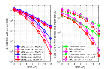
Fig. 5 a) shows the BER performance of the MMD-Max-Link and QN-Max-Link protocols, for , = 3, 5 and 10, , BPSK and perfect CSI. Note that for multiple antennas the BER performance of the MMD-Max-Link scheme is much better than that of QN-Max-Link for the total range of SNR values tested. When we increase , the MMD-Max-Link has its performance improved. The same does not happen to QN-Max-Link, as the QN criterion does not take the metric into account. This result validates the accuracy of our analysis in Section IV, illustrating that a better theoretical PEP worst case performance achieved by the MMD relay selection criterion implies also a better BER performance for the MMD-Max-Link protocol. Fig. 5 b) shows the Switched Max-Link, the MMD-Max-Link and the conventional MIMO BER performance comparison for , , , , QPSK, perfect and imperfect CSI ( and ). The QN-Max-Link was not considered as its performance is worse than the performance of the proposed protocol. Both for perfect and imperfect CSI, the performance of Switched Max-Link is considerably better than that of the conventional MIMO for a wide range of SNR values. Switched Max-Link also outperforms MMD-Max-Link, and has resiliency in low transmit SNR conditions. Moreover, we note that outdated CSI results in diversity loss.
V-B Performance under asymmetric channels
In the following we consider the BER, sum-rate and average delay performances of the proposed and existing schemes under asymmetric channels.
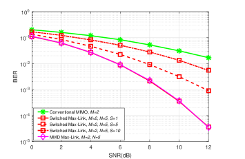
Fig. 6 shows the BER performance of the Switched Max-Link, MMD-Max-Link and the conventional MIMO protocols, for , = 5, , , 5 and 10, BPSK, perfect CSI and low power links ( and ). The performance of the proposed Switched Max-Link scheme, for , is very close to that of the MMD-Max-Link, illustrating the importance of switching to the Max-Link mode, when we have low power links.

Fig. 7 shows the sum-rate (assuming Gaussian signaling) and the average delay performances of the Switched Max-Link, MMD-Max-Link and the conventional MIMO protocols, for the same configuration described in Fig. 6. We notice that the simulated average delay of the MMD-Max-Link is equal to its theoretical value . This result validates the accuracy of our analysis in Section IV. When we increase in the proposed Switched Max-Link, the average delay reduces and is less than 1 time slot, when is equal to 10. This result also validates the accuracy of our analysis. Moreover, the sum-rate of the proposed Switched Max-Link, for SNR values less than 6dB, is increased when we reduce , and, for SNR values greater than 6dB, it is increased when we increase .

Fig. 8 shows the BER performance of the Switched Max-Link, MMD-Max-Link and the conventional MIMO protocols, for , = 5, , , 3 and 5, BPSK, perfect CSI and high power links ( and ). The performance of the proposed Switched Max-Link scheme, for the values tested, is better than that of the conventional MIMO and considerably better than that of the MMD-Max-Link scheme, illustrating the importance of switching to DT mode, when we have high power links.

Fig. 9 shows the sum-rate and the average delay performances of the Switched Max-Link, MMD-Max-Link and the conventional MIMO protocols, for the same configuration described in Fig. 8. When we increase in the proposed Switched Max-Link, the average delay reduces and is less than 1 time slot, when is greater than 3. Moreover, the sum-rate performance of the proposed Switched Max-Link (for all the values tested) is very close to that of conventional MIMO, for all the range of SNR values tested, and considerably higher than that of the MMD-Max-Link scheme.

Fig. 10 shows the BER performance of the Switched Max-Link, MMD-Max-Link and the conventional MIMO protocols, for , = 5, , , BPSK, perfect CSI and low power or links ( and 1, and 1, ). Switched Max-Link outperforms conventional MIMO and MMD-Max-Link schemes, illustrating that even with low power or links, Switched Max-Link has a better performance than that of conventional MIMO.
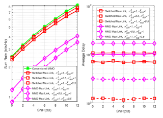
Fig. 11 shows the sum-rate and the average delay performances of the Switched Max-Link, MMD-Max-Link and the conventional MIMO protocols, for the same configuration described in Fig. 10. When we have low power links ( and ), the probalility of selecting an link is less than the probability of selecting an link, so the average delay is less than the average delay with equal unit power channels ( and ). Otherwise, when we have low power links ( and ), the probalility of selecting an link is less than the probability of selecting an link, so the average delay is greater than the average delay with equal unit power channels. Moreover, the sum-rate performance of the proposed Switched Max-Link is very close to that of conventional MIMO, even for low power or links, and considerably higher than that of the MMD-Max-Link scheme. The slightly worse sum-rate performance of Switched Max-Link compared to conventional MIMO is justified, as the proposed scheme is able to transmit with higher order modulation due to the improved BER performance.
V-C Performance for Massive MIMO
In the following we consider the performance of the proposed scheme for massive MIMO (with a small number of antennas at and and a large number of antennas at the relays).

Fig. 12 shows the BER and sum-rate performances of the Switched Max-Link protocol, for , , 8, 16, 32, 64 and 128, = 5, , , BPSK, perfect CSI and unit power links (). Both the BER and sum-rate performances are considerably improved when we increase , illustrating that the proposed protocol can be used for massive MIMO (with a small number of antennas at and and a large number of antennas at the relays). This result validates the accuracy of our analysis, as when , the maximization of the minimum distances related to also implies the maximization of the minimum value of the PEP argument. Note that the achieved BER values were considerably reduced, thus the transmit signal-to-noise ratio SNR () ranges from 0 to 10 dB.
VI Conclusions
In this paper, we have presented the benefits of using a novel relay selection protocol based on switching and the selection of the best link, denoted as Switched Max-Link. We then consider the MMD relay selection criterion for MIMO systems, along with algorithms that are incorporated into the proposed Switched Max-Link protocol. Switched Max-Link was evaluated experimentally and outperformed the conventional direct transmission and the existing QN Max-Link scheme. Despite the higher complexity of the proposed Switched Max-Link with the MMD relay selection criterion, it is an attractive solution for relaying systems with source and destination nodes equipped with a small number of antennas and relay nodes equipped with a small or large number of antennas due to its high performance and reduced delay.
Appendix A Proof of
The selected matrix by the MMD criterion, that maximizes the minimum distances , is given by
| (50) |
where and .
As , where =, for and , or = 2 , for , we have
| (51) |
So, the maximized minimum value of the PEP argument associated to is given by
| (52) |
However, the selected matrix by the QN criterion is given by
| (53) |
where and .
The minimum value of the PEP argument associated to
is given by
| (54) |
If the sum of the powers of the coefficients of one of the columns (or the combination of 2 or more columns by addition or subtraction) of a selected submatrix and/or matrix is very small or tends to zero, we have
| (55) |
and, consequently: .
As MMD maximizes , the submatrix and/or matrix selected by QN will be different from the selected by MMD:
and
We have seen that the MMD criterion computes all the values of and stores its minimum value (), for each submatrix . Then, this criterion selects the matrix () that is associated to the maximum () and the associated relay. As the goal of this criterion is to maximize the argument of the PEP in its worst case (), another criterion such as QN can not outperform MMD but only equalize its performance, resulting in the same , if the matrix selected by QN () is equal to . Therefore, if we have , this implies that the associated to () is greater than the associated to (). As there are cases where , we may conclude that: .
References
- [1] J. N. Laneman, D. N. C. Tse, G. W. Wornell, "Cooperative Diversity in Wireless Networks: Efficient Protocols and Outage Behavior", in IEEE Trans. Inf. Theory., vol. 50, no. 12, pp. 3062-3080, Dec. 2004.
- [2] A. Sendonaris, E. Erkip and B. Aazhang, “User cooperation diversity - parts I and II,” IEEE Trans. Commun., vol. 51, no. 11, pp. 1927–1948, Nov. 2003.
- [3] T. M. Cover, “Capacity Theorems for the Relay Channel”, IEEE Trans. Inf. Theory., vol. 25, no. 5, pp. 572-584, Sept. 1979.
- [4] A. Ikhlef, D. S. Michalopoulos and R. Schober, "Max-Max Relay Selection for Relays with Buffers," in IEEE Trans. Wireless Commun., vol. 11, no. 3, pp. 1124-1135, March 2012.
- [5] T. Hesketh, R. C. De Lamare and S. Wales, "Joint maximum likelihood detection and link selection for cooperative MIMO relay systems," in IET Commun., vol. 8, no. 14, pp. 2489-2499, Sept. 25 2014.
- [6] P. Clarke and R. C. de Lamare, "Transmit Diversity and Relay Selection Algorithms for Multirelay Cooperative MIMO Systems," in IEEE Trans. Veh. Tech., vol. 61, no. 3, pp. 1084-1098, March 2012.
- [7] N. Zlatanov, A. Ikhlef, T. Islam and R. Schober, "Buffer-aided cooperative communications: opportunities and challenges," in IEEE Commun. Mag., vol. 52, no. 4, pp. 146-153, April 2014.
- [8] C. Hoymann, “Relaying in 3GPP LTE”, ITG Fachtagung – IMT Advanced, Ericsson Research – AACHEN, July 8, 2010 [Online]. Available: https://www.slideshare.net/allabout4g/relaying-in-3gpp-lteadvanced
- [9] Ericsson, “5 G Radio Access”, Ericsson White Paper, Uen 284 23-3204 Rev C | Apr. 2016 [Online]. Available: https://www.ericsson.com/assets/local/publications/white-papers/wp-5g.pdf.
- [10] J. Gu, R. C. de Lamare and M. Huemer, "Buffer-Aided Physical-Layer Network Coding with Optimal Linear Code Designs for Cooperative Networks," in IEEE Trans. Commun., vol. 66, no. 6, pp. 2560-2575, June 2018.
- [11] I. Krikidis, T. Charalambous, and J. Thompson, “Buffer-Aided Relay Selection for Cooperative Diversity Systems Without Delay Constraints,” IEEE Trans. Wireless Commun., vol. 11, no. 5, pp. 1957–1967, May 2012.
- [12] N. Nomikos et al., "A Survey on Buffer-Aided Relay Selection," in IEEE Commun. Surveys & Tutorials, vol. 18, no. 2, pp. 1073-1097, Second quarter 2016.
- [13] T. Charalambous, N. Nomikos, I. Krikidis, D. Vouyioukas and M. Johansson, “Modeling buffer-aided relay selection in networks with direct transmission capability,” IEEE Commun. Lett., vol. 19, no. 4, pp. 649–652, April 2015.
- [14] Z. Tian, G. Chen, Y. Gong, Z. Chen and J. A. Chambers, "Buffer-Aided Max-Link Relay Selection in Amplify-and-Forward Cooperative Networks," in IEEE Trans. Veh. Tech., vol. 64, no. 2, pp. 553-565, Feb. 2015.
- [15] S. Luo and K. C. Teh, "Buffer State Based Relay Selection for Buffer-Aided Cooperative Relaying Systems," in IEEE Trans. Wireless Commun., vol. 14, no. 10, pp. 5430-5439, Oct. 2015.
- [16] P. Xu, Z. Ding, I. Krikidis and X. Dai, "Achieving Optimal Diversity Gain in Buffer-Aided Relay Networks With Small Buffer Size," in IEEE Trans. Veh. Tech., vol. 65, no. 10, pp. 8788-8794, Oct. 2016.
- [17] M. Oiwa, C. Tosa and S. Sugiura, "Theoretical Analysis of Hybrid Buffer-Aided Cooperative Protocol Based on Max–Max and Max–Link Relay Selections," in IEEE Trans. Veh. Tech., vol. 65, no. 11, pp. 9236-9246, Nov. 2016.
- [18] D. Poulimeneas, T. Charalambous, N. Nomikos, I. Krikidis, D. Vouyioukas and M. Johansson, "Delay- and diversity-aware buffer-aided relay selection policies in cooperative networks," 2016 IEEE Wireless Comm. and Netw. Conf., Doha, 2016, pp. 1-6.
- [19] A. A. M. Siddig and M. F. M. Salleh, "Balancing Buffer-Aided Relay Selection for Cooperative Relaying Systems," in IEEE Trans. Veh. Tech., vol. 66, no. 9, pp. 8276-8290, Sept. 2017.
- [20] B. R. Manoj, R. K. Mallik and M. R. Bhatnagar, "Performance Analysis of Buffer-Aided Priority-Based Max-Link Relay Selection in DF Cooperative Networks," in IEEE Trans. Commun., vol. 66, no. 7, pp. 2826-2839, July 2018.
- [21] S. M. Kim and M. Bengtsson, "Virtual full-duplex buffer-aided relaying in the presence of inter-relay interference," in IEEE Trans. Wireless Commun., vol. 15, no. 4, pp. 2966-2980, April 2016.
- [22] T. Charalambous, S. M. Kim, N. Nomikos, M. Bengtsson and M. Johansson, "Relay-pair selection in buffer-aided successive opportunistic relaying using a multi-antenna source," in Ad Hoc Netw., vol. 84, pp. 29-41, 2019.
- [23] F. L. Duarte and R. C. de Lamare, "Switched Max-Link Buffer-Aided Relay Selection for Cooperative Multiple-Antenna Systems," SCC 2019; 12th Int. ITG Conf. on Systems, Commun. and Coding, Rostock, Germany, 2019, pp. 1-6.
- [24] F. L. Duarte and R. C. de Lamare, "Buffer-Aided Max-Link Relay Selection for Multi-Way Cooperative Multi-Antenna Systems," in IEEE Commun. Lett., vol. 23, no. 8, pp. 1423-1426, Aug. 2019.
- [25] F. L. Duarte and R. C. de Lamare, "Buffer-Aided Max-Link Relay Selection for Two-Way Cooperative Multi-Antenna Systems", in 2019 16th International Symposium on Wireless Communication Systems (ISWCS), Oulu, Finland, 2019, pp. 288-292.
- [26] F. L. Duarte and R. C. de Lamare, “Switched Max-Link Relay Selection Based on Maximum Minimum Distance for Cooperative MIMO Systems", IEEE Transactions on Vehicular Technology, 2020.
- [27] H. Joudeh and B. Clerckx, "Sum-Rate Maximization for Linearly Precoded Downlink Multiuser MISO Systems With Partial CSIT: A Rate-Splitting Approach," in IEEE Trans. Commun., vol. 64, no. 11, pp. 4847-4861, Nov. 2016.
- [28] X. Lu and R. C. de Lamare, “Buffer-aided relay selection for physical-layer security in wireless networks,” WSA 2015; 19th Int. ITG Workshop on Smart Antennas, Ilmenau, Germany, 2015, pp. 1–5.
- [29] R. Shankar, I. Kumar, A. Kumari, K. N. Pandey and R. K. Mishra, "Pairwise error probability analysis and optimal power allocation for selective decode-forward protocol over Nakagami-m fading channels," 2017 Int. Conf. on Algorithms, Methodology, Models and Applications in Emerging Technologies (ICAMMAET), Chennai, 2017, pp. 1-6.
- [30] T. Peng and R. C. de Lamare, "Adaptive Buffer-Aided Distributed Space-Time Coding for Cooperative Wireless Networks," in IEEE Trans. Commun., vol. 64, no. 5, pp. 1888-1900, May 2016.
- [31] I. E. Telatar, “Capacity of multi-antenna gaussian channels” AT&T Bell Laboratories, Internal Tech. Memo, June 1995.
-
[32]
B. Holter, "On the Capacity of the MIMO Channel - A Tutorial Introduction" [Online]. Available: http://citeseerx.ist.psu.edu/viewdoc/download?doi=10.1.1.503.3015&rep=
rep1&type=pdf. - [33] Z. Tian, G. Chen, Y. Gong, Z. Chen, and J. Chambers, “Buffer-Aided Max-Link Relay Selection in Amplify-and-Forward Cooperative Networks,” IEEE Trans. Veh. Tech., vol. 64, no. 2, pp. 553–565, Feb. 2015.
- [34] R. C. de Lamare, "Massive MIMO systems: Signal processing challenges and future trends," in URSI Radio Science Bulletin, vol. 2013, no. 347, pp. 8-20, Dec. 2013.
- [35] W. Zhang et al., "Large-Scale Antenna Systems With UL/DL Hardware Mismatch: Achievable Rates Analysis and Calibration," in IEEE Transactions on Communications, vol. 63, no. 4, pp. 1216-1229, April 2015.
- [36] R. C. de Lamare and R. Sampaio-Neto, "Adaptive MBER decision feedback multiuser receivers in frequency selective fading channels," in IEEE Communications Letters, vol. 7, no. 2, pp. 73-75, Feb. 2003.
- [37] R. C. De Lamare, R. Sampaio-Neto and A. Hjorungnes, "Joint iterative interference cancellation and parameter estimation for cdma systems," in IEEE Communications Letters, vol. 11, no. 12, pp. 916-918, December 2007.
- [38] R. C. De Lamare and R. Sampaio-Neto, “Minimum Mean-Squared Error Iterative Successive Parallel Arbitrated Decision Feedback Detectors for DS-CDMA Systems,” in IEEE Transactions on Communications, vol. 56, no. 5, pp. 778-789, May 2008.
- [39] Y. Cai and R. C. de Lamare, "Space-Time Adaptive MMSE Multiuser Decision Feedback Detectors With Multiple-Feedback Interference Cancellation for CDMA Systems," in IEEE Transactions on Vehicular Technology, vol. 58, no. 8, pp. 4129-4140, Oct. 2009.
- [40] R. C. de Lamare and R. Sampaio-Neto, "Adaptive Reduced-Rank Equalization Algorithms Based on Alternating Optimization Design Techniques for MIMO Systems," in IEEE Transactions on Vehicular Technology, vol. 60, no. 6, pp. 2482-2494, July 2011.
- [41] P. Li, R. C. de Lamare and R. Fa, “Multiple Feedback Successive Interference Cancellation Detection for Multiuser MIMO Systems,” in IEEE Trans. on Wireless Comm., vol. 10, no. 8, pp. 2434-2439, Aug. 2011.
- [42] P. Li and R. C. De Lamare, "Adaptive Decision-Feedback Detection With Constellation Constraints for MIMO Systems," in IEEE Transactions on Vehicular Technology, vol. 61, no. 2, pp. 853-859, Feb. 2012.
- [43] R. C. de Lamare, “Adaptive and Iterative Multi-Branch MMSE Decision Feedback Detection Algorithms for Multi-Antenna Systems,” in IEEE Transactions on Wireless Communications, vol. 12, no. 10, pp. 5294-5308, October 2013.
- [44] P. Li and R. C. de Lamare, "Distributed Iterative Detection With Reduced Message Passing for Networked MIMO Cellular Systems," in IEEE Transactions on Vehicular Technology, vol. 63, no. 6, pp. 2947-2954, July 2014.
- [45] Y. Cai, R. C. de Lamare, B. Champagne, B. Qin and M. Zhao, "Adaptive Reduced-Rank Receive Processing Based on Minimum Symbol-Error-Rate Criterion for Large-Scale Multiple-Antenna Systems," in IEEE Transactions on Communications, vol. 63, no. 11, pp. 4185-4201, Nov. 2015.
- [46] A. G. D. Uchoa, C. T. Healy and R. C. de Lamare, "Iterative Detection and Decoding Algorithms for MIMO Systems in Block-Fading Channels Using LDPC Codes," in IEEE Transactions on Vehicular Technology, vol. 65, no. 4, pp. 2735-2741, April 2016.
- [47] Z. Shao, R. C. de Lamare and L. T. N. Landau, "Iterative Detection and Decoding for Large-Scale Multiple-Antenna Systems With 1-Bit ADCs," in IEEE Wireless Communications Letters, vol. 7, no. 3, pp. 476-479, June 2018.
- [48] R. B. Di Renna and R. C. de Lamare, "Adaptive Activity-Aware Iterative Detection for Massive Machine-Type Communications," in IEEE Wireless Communications Letters, vol. 8, no. 6, pp. 1631-1634, Dec. 2019.
- [49] K. Zu and R. C. de Lamare, "Low-Complexity Lattice Reduction-Aided Regularized Block Diagonalization for MU-MIMO Systems," in IEEE Communications Letters, vol. 16, no. 6, pp. 925-928, June 2012.
- [50] Y. Cai, R. C. de Lamare, and R. Fa, “Switched Interleaving Techniques with Limited Feedback for Interference Mitigation in DS-CDMA Systems," IEEE Transactions on Communications, vol.59, no.7, pp.1946-1956, July 2011.
- [51] Y. Cai, R. C. de Lamare, D. Le Ruyet, “Transmit Processing Techniques Based on Switched Interleaving and Limited Feedback for Interference Mitigation in Multiantenna MC-CDMA Systems," IEEE Transactions on Vehicular Technology, vol.60, no.4, pp.1559-1570, May 2011.
- [52] K. Zu, R. C. de Lamare and M. Haardt, "Generalized Design of Low-Complexity Block Diagonalization Type Precoding Algorithms for Multiuser MIMO Systems," IEEE Transactions on Communications, vol. 61, no. 10, pp. 4232-4242, October 2013.
- [53] W. Zhang et al., "Widely Linear Precoding for Large-Scale MIMO with IQI: Algorithms and Performance Analysis," IEEE Transactions on Wireless Communications, vol. 16, no. 5, pp. 3298-3312, May 2017.
- [54] K. Zu, R. C. de Lamare and M. Haardt, "Multi-Branch Tomlinson-Harashima Precoding Design for MU-MIMO Systems: Theory and Algorithms," IEEE Transactions on Communications, vol. 62, no. 3, pp. 939-951, March 2014.
- [55] L. Zhang, Y. Cai, R. C. de Lamare and M. Zhao, "Robust Multibranch Tomlinson-Harashima Precoding Design in Amplify-and-Forward MIMO Relay Systems," IEEE Transactions on Communications, vol. 62, no. 10, pp. 3476-3490, Oct. 2014.
- [56] L. T. N. Landau and R. C. de Lamare, "Branch-and-Bound Precoding for Multiuser MIMO Systems With 1-Bit Quantization," in IEEE Wireless Communications Letters, vol. 6, no. 6, pp. 770-773, Dec. 2017.
- [57] T. Wang, R. C. de Lamare, and P. D. Mitchell, “Low-Complexity Set-Membership Channel Estimation for Cooperative Wireless Sensor Networks," IEEE Transactions on Vehicular Technology, vol.60, no.6, pp.2594-2607, July 2011.
- [58] T. Wang, R. C. de Lamare and A. Schmeink, "Joint linear receiver design and power allocation using alternating optimization algorithms for wireless sensor networks," IEEE Trans. on Vehi. Tech., vol. 61, pp. 4129-4141, 2012.
- [59] R. C. de Lamare, “Joint iterative power allocation and linear interference suppression algorithms for cooperative DS-CDMA networks", IET Communications, vol. 6, no. 13 , 2012, pp. 1930-1942.
- [60] T. Peng, R. C. de Lamare and A. Schmeink, “Adaptive Distributed Space-Time Coding Based on Adjustable Code Matrices for Cooperative MIMO Relaying Systems”, IEEE Transactions on Communications, vol. 61, no. 7, July 2013.
- [61] T. Peng and R. C. de Lamare, “Adaptive Buffer-Aided Distributed Space-Time Coding for Cooperative Wireless Networks," IEEE Transactions on Communications, vol. 64, no. 5, pp. 1888-1900, May 2016.
- [62] J. Gu, R. C. de Lamare and M. Huemer, “Buffer-Aided Physical-Layer Network Coding with Optimal Linear Code Designs for Cooperative Networks," IEEE Transactions on Communications, 2018.
- [63] M. L. Honig and J. S. Goldstein, “Adaptive reduced-rank interference suppression based on the multistage Wiener filter," IEEE Transactions on Communications, vol. 50, no. 6, June 2002.
- [64] Q. Haoli and S.N. Batalama, “Data record-based criteria for the selection of an auxiliary vector estimator of the MMSE/MVDR filter", IEEE Transactions on Communications, vol. 51, no. 10, Oct. 2003, pp. 1700 - 1708.
- [65] R. C. de Lamare and R. Sampaio-Neto, “Reduced-Rank Adaptive Filtering Based on Joint Iterative Optimization of Adaptive Filters", IEEE Signal Processing Letters, Vol. 14, no. 12, December 2007.
- [66] R. C. de Lamare and R. Sampaio-Neto, “Adaptive Reduced-Rank Processing Based on Joint and Iterative Interpolation, Decimation and Filtering", IEEE Transactions on Signal Processing, vol. 57, no. 7, July 2009, pp. 2503 - 2514.
- [67] R. C. de Lamare and R. Sampaio-Neto, “Reduced-rank space-time adaptive interference suppression with joint iterative least squares algorithms for spread-spectrum systems," IEEE Trans. Vehi. Technol., vol. 59, no. 3, pp. 1217-1228, Mar. 2010.
- [68] R. C. de Lamare and R. Sampaio-Neto, “Adaptive reduced-rank equalization algorithms based on alternating optimization design techniques for MIMO systems," IEEE Trans. Vehi. Technol., vol. 60, no. 6, pp. 2482-2494, Jul. 2011.