Decoherence Effects Break Reciprocity in Matter Transport
Abstract
The decoherence of quantum states defines the transition between the quantum world and classical physics. Decoherence or, analogously, quantum mechanical collapse events pose fundamental questions regarding the interpretation of quantum mechanics and are technologically relevant because they limit the coherent information processing performed by quantum computers. We have discovered that the transition regime enables a novel type of matter transport. Applying this discovery, we present nanoscale devices in which decoherence, modeled by random quantum jumps, produces fundamentally novel phenomena by interrupting the unitary dynamics of electron wave packets. Noncentrosymmetric conductors with mesoscopic length scales act as two-terminal rectifiers with unique properties. In these devices, the inelastic interaction of itinerant electrons with impurities acting as electron trapping centers leads to a novel steady state characterized by partial charge separation between the two leads, or, in closed circuits to the generation of persistent currents. The interface between the quantum and the classical worlds therefore provides a novel transport regime of value for the realization of a new category of mesoscopic electronic devices.
I Introduction
The measurement process is a mysterious phenomenon at the heart of quantum physics. Starting with the Copenhagen interpretation [1, 2], numerous approaches have attempted to describe this phenomenon. For an overview, see, e.g. [3]. The Copenhagen interpretation, for example, states that a measurement causes a spontaneous collapse of the wave function [4], whereas the decoherence theory attributes the apparent collapse to the entanglement of the system with its environment [5, 6, 7]. Hitherto unknown processes are also considered to cause physically real quantum collapses, which for macroscopic systems create an observer-independent reality [8]. In this work, we assume that physically real decoherence or collapse events are initiated by inelastic interactions and show that they impact mesoscopic transport without a macroscopic measurement process. This concept underlies the quantum trajectories approach widely and successfully used in quantum optics [9, 10, 11, 12, 13, 14]. We shall show that this method, applied to solid state systems on the nanoscale, predicts nonreciprocal transport properties of electrons.
We analyze the mesoscopic transport of electrons by considering the event-type character of inelastic scattering, which initiates collapse processes [15]. The idea behind this approach is presented in Fig. 1. Whereas electron transport in the quantum regime is described by propagating extended waves and interference effects (Fig. 1a), it is characterized in the classical world by scattering events of particles (Fig. 1c). These two transport regimes are exemplified by the Landauer-Büttiker formalism [16, 17] and the Drude-Sommerfeld model, described by the Boltzmann equation [18, 19]. We focus here on the transition regime between classical and quantum transport and describe the charge carriers as coherent wave packets of finite size (Fig. 1b). Existing formalisms assessing this regime are usually based on the Kubo formalism, which ensemble-averages the effects of collapses and dephasing processes [20]. Such effects include the broadening of energy levels [21] or “washing out of states” [22] and adding noise to wave functions’ amplitudes and phases [23, 24, 25]. These methods find a smooth crossover from the quantum regime to the classical world [26, 27] because decoherence is modeled as a decay process phenomenologically.
In contrast, the quantum trajectory approach treats an inelastic event (a “quantum jump”) as an individual event that does or does not take place. It breaks time-reversal symmetry by initiating a collapse of the wave function and occurs in real space at a distinct location and time [15]. The quantum jumps can equivalently be described by an appropriate Lindblad master equation for the reduced density matrix of the observed system [28] which in our case consists of the electrons in a nanoscopic device. The spontaneous breaking of time-reversal invariance of the microscopic dynamics does not fit the assumptions underlying Onsager’s reciprocity relations [29, 30]. It is therefore not guaranteed that the transport must be reciprocal if quantum collapse processes are relevant.
This irreversibility is caused on a microscopic level by inelastic scattering events. It is therefore impossible to model it appropriately by a macroscopic procedure like tracing over unobserved degrees of freedom, as implemented by the methods mentioned above. Instead we shall use a description taking into account those events directly (see below). We exploit this intrinsic irreversibility to design novel electronic devices. These nonunitary quantum electronic devices work as follows. To start, the devices are nanostructured into noncentrosymmetric shapes. The spatial asymmetry induces a temporal asymmetry; the transit time of a wave packet depends on whether the electron travels forward or backward through the device as shown in section II. This is because the transit time depends on the interference of the wave function due to the unitary dynamics. On the other hand, decoherence is caused by inelastic scattering events as characterized by the average time between such events. Therefore, the number of quantum jumps per passage of the electron through the device depends on and is thus nonreciprocal. In one direction the electron transport is more coherent, in the other less so. The intrinsic irreversibility of the quantum mechanical decoherence process leads to nonreciprocity of electron transport.
Here, we demonstrate this device concept by modeling the electron transport in a set of noncentrosymmetric devices [31, 32, 33]. These include devices with longitudinal asymmetry, devices with transverse asymmetry subject to a magnetic field, and two-path interferometers. The devices are constructed from idealized model materials that are described by the single particle picture and by perfect screening. The calculations were done by applying the Lindblad equation [28], or using a direct, stochastic implementation of the wave-function collapse, by computing the quantum trajectory of the particle [9, 10, 11, 12, 13, 14]. Both kinds of calculations cover the entire range from coherent quantum transport to classical diffusive transport. As we work in the single particle picture, the Fermi statistics of the electron plays no role. For a recent proposal to implement Lindblad dynamics in the Meir-Wingreen transport formula, see [34, 35]. Nonreciprocal transport of wave packets is achieved in all devices in a well defined window of scattering rates, yielding a peak of the nonreciprocity at a decoherence rate of (see section III). Crucially, in the limits of large and small scattering rates the transport is reciprocal. Therefore, this device concept illustrates the emergence of new functionality in electron transport right in the transition regime between quantum physics and classical physics. Having established the nonreciprocity for excited states (wave packets), we address in section IV the question whether the effect persists close to thermal equilibrium as described by a thermal density matrix. It turns out that the thermal equilibrium taken as a starting point of the state evolution is unstable against the collapse dynamics or decoherence. Novel time-independent states are established which show charge separation between the two leads, and, for closed systems, persistent currents.
II Nonreciprocal dynamics of wave packets for
Figure 2 shows the structure of the devices considered. The conductors connect two ports, and , and are shaped asymmetrically perpendicular to or in the direction of the current flow (transversal and longitudinal asymmetry). We compare these conductors to Aharonov–Bohm rings [36, 37] with a transversal asymmetry and to symmetric devices. To find the electron dynamics in the devices, we solve Schrödinger’s equation for the given device geometries by exact diagonalization of the tight-binding Hamiltonian (see Appendix C). Electron-electron interactions clearly modify the electron dynamics but, following the arguments used in Landauer’s theory of ballistic transport [16, 17], can be neglected to first approximation in these nanoscopic devices. Likewise, we do not consider additional elastic impurity scattering because this mechanism only adds the time-reversal invariant weak localization correction to the ballistic dynamics but does not affect the breaking of the time-reversal invariance which is the focus of the investigation.
The electron waves emitted by or into the one-dimensional conductor are described by Gaussian wave packets with momenta centered at , being the lattice constant. To consider transport across devices with a similar size as the electron wave packets, small, dispersive wave packets were chosen. The description in terms of wave packets, which forms the basis of the well-established semiclassical description of electron dynamics [38], is central to our calculations, because Bloch-waves lack time dependence. Since we use the exact eigenfunctions of the single-particle Hamiltonian to compute the time evolution of the states, the results in this section are obtained in the unitary quantum regime.
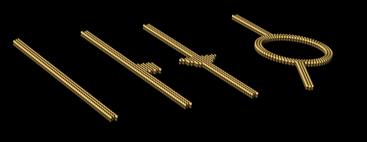
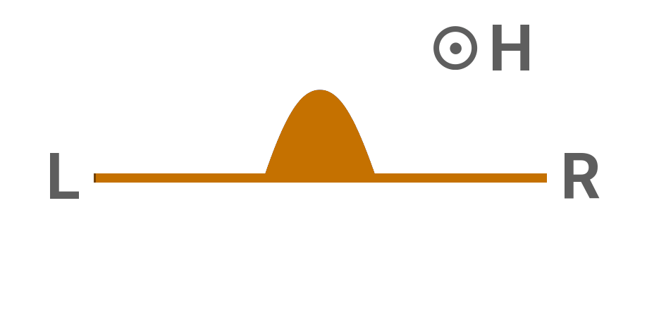
Figure 3 displays the probability that the electron has reached one of the ports of the conductor with the transverse asymmetry as a function of time after the electron emission. As demanded by the unitarity of the scattering matrix, these probabilities are reciprocal in the long-time limit [21, 26]. In contrast, the time evolution does depend on the travel direction [31, 32, 33]. The left-right symmetry is broken because the phase shifts of the individual plane waves are nonreciprocal. As the phase shifts are also -dependent, they influence the temporal behavior of the wave packet, which comprises many plane waves with different -values. This leads to , where denotes the time spent in the device by a wave packet coming from port before it leaves through port (see also videos 8, 9).




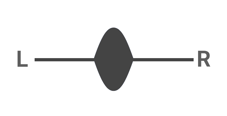
We find that a nonreciprocal temporal dependence of particle transport is a generic property of many quantum devices with appropriately broken symmetries. Fig. 3a shows a device that is symmetric in the transversal direction, but asymmetric in the longitudinal direction. In these devices, the reflected electrons follow a nonreciprocal temporal dependence even without an applied magnetic field. The nonreciprocal temporal dependence has been predicted for asymmetric Rashba rings and for Aharonov–Bohm rings biased with magnetic fields [31, 32] (Fig. 3c, videos 9a and 9b). Note that the reflection probabilities , are equal for the systems in Fig. 3b and Fig. 3c, while the transmission probabilities , are equal in the system of Fig. 3a without magnetic field. This feature reflects the symmetries of the scattering matrix under spatial inversion and time-reversal [33]. In contrast, conductors without adequately broken symmetries (Fig. 3d) show reciprocal dynamics.
III Nonreciprocal behavior of wave packets for any
In order to calculate the transport in the transition regime between unitary quantum physics and classical physics, we now add decoherence to the dynamics of the wave packets. This decoherence is commonly characterized by the phase-breaking time . We expect the physics of the transition regime to emerge when the defect density causes to be of the order of the average electron transmission time . As shown, the electron transmission time is not necessarily equal for both transmission directions. In those cases, electrons that pass the device in the slower direction suffer stronger decoherence than those that pass in the faster one. The transmission probabilities for both directions, however, are guaranteed to be equal only if the degree of phase-breaking is equal in both directions. Therefore, the transmission probabilities are expected to be possibly nonreciprocal in devices with nonreciprocal decoherence.
The interaction with the environment is mediated by one or more sites of the tight-binding lattice that we use to model the device, see Appendix C. Apart from the localized nature of the interaction, we introduce no constraint on the nature of the decoherence or collapse processes, which may be caused e.g. by local lattice distortions (local phonons) or the internal degrees of freedom of an impurity giving rise to a localized resonant level. We are interested in a description of the electron dynamics, i.e. the time evolution of the reduced density matrix of the (single) electron. This reduced matrix is obtained from the full density matrix by tracing over the unobserved degrees of freedom. The general form of the resulting time evolution is a time-local master equation for that preserves complete positivity [28]:
| (1) |
Here, is the single particle Hamiltonian of the system without the impurities. The Lindblad dissipators depend on the index of the site at which an impurity and the concomitant electronic level are located. They are generally defined as
| (2) |
where denotes the so-called jump operators. For devices A, B and D we choose hermitean jump operators that project the electron wave function onto the site , i.e. , with . This mechanism corresponds to a measurement of the occupation of site without read-out. For device C we chose a projection onto the full subspace spanned by the sites of one interferometer arm. In both cases the localization erases the information about the momentum and phase of the electron trapped at the site . All jump operators are multiplied with the -independent rate , where is the mean time between two phase-breaking scattering events. After release from the trap, the electron state evolves again according to the Schrödinger equation given by .
To quantify the effects of the decoherence on the transport, we prepare the electron at time as a Gaussian wave packet which enters the system either at port or port . We integrate the time-dependent local probability current at site in the left or right port until time to obtain transmission and reflection probabilities (see Appendix B). Reciprocal transport demands for sufficiently large . Figure 4 shows the nonreciprocity as function of computed with Eq. 1 and a set of localization centers at positions within the devices (see Appendix C). For the ballistic regime, i.e. for small , indeed vanishes.
However, sorting occurs in the asymmetric devices A, B and C in a specific window of . In this window, electrons that are emitted by and reach port with a higher probability than port . The window for nonreciprocal transport matches the inverse device transit time which is a function of the properties of the chosen wave packet. Furthermore, we observe a restoration of reciprocity at high inelastic scattering rates , corresponding to the crossover to classical diffusive transport. Notably, the sorting is completely absent for the symmetric device D.
The physics behind the nonreciprocal transport happening in a well-defined window of may be intuitively understood by unraveling the Lindblad equation Eq. 1 as a stochastic evolution of the wave function. Following this concept, we consider events at randomly chosen times with a mean spacing . As before, the rate of this Poisson process is proportional to the coupling between electrons and the defect or phonon systems. Between the “collapse times” and the wave function evolves unitarily with the Hamiltonian . At and the wave function changes according to the corresponding jump operator . Two outcomes can be distinguished: In the first case, the wave function is projected onto an eigenstate of the operator , it becomes with probability as given by the Born rule [4]. In the second case the “measurement result” is negative: The state is projected onto the orthogonal complement of and changes to with probability . For , the wave packet evolves again unitarily until it undergoes a second random inelastic scattering event at or leaves the system via the two ports (see video 10).
Due to the stochastic time-evolution, the transmission probability is itself a random variable. To obtain its distribution function , we consider an ensemble of many stochastic quantum trajectories. Figure 4a shows the average for such evolutions for device A. As shown in the figure, the results obtained by this stochastic implementation of the wave-function collapse are quantitatively consistent with the calculation based on the Lindblad-formalism.


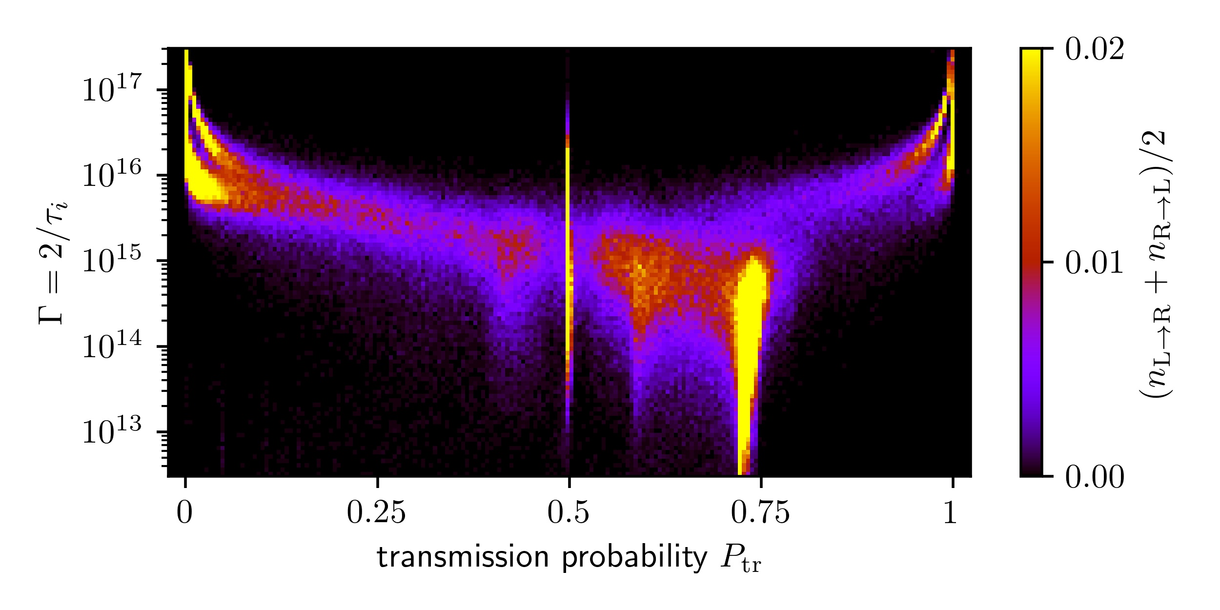
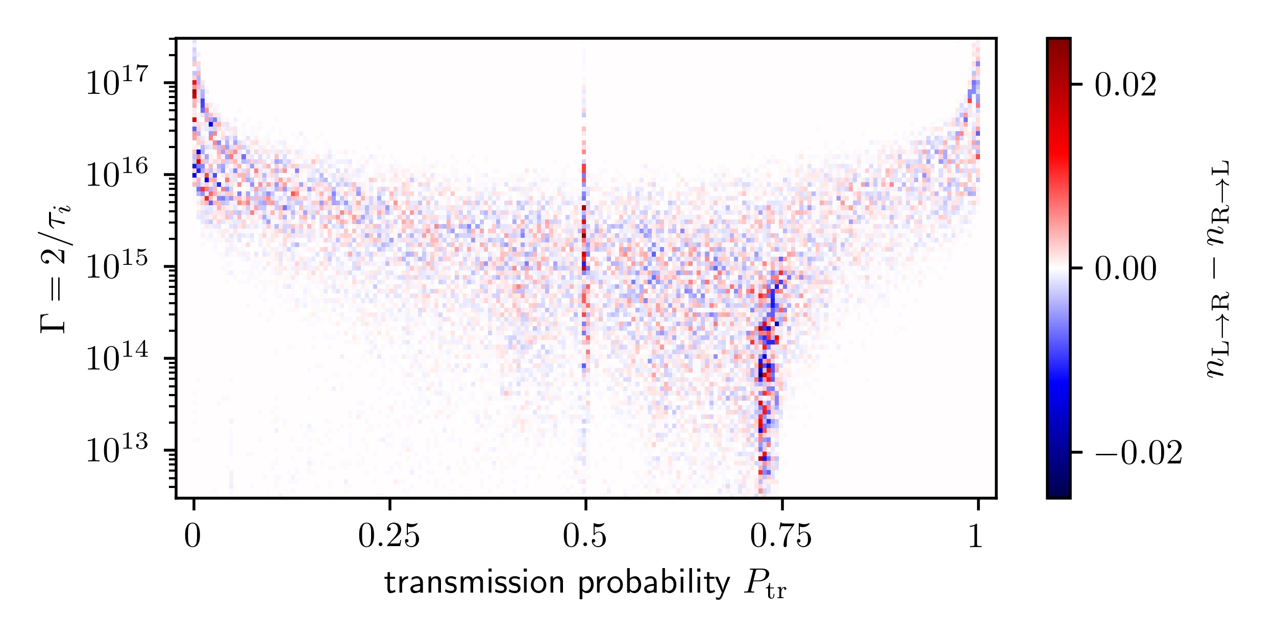
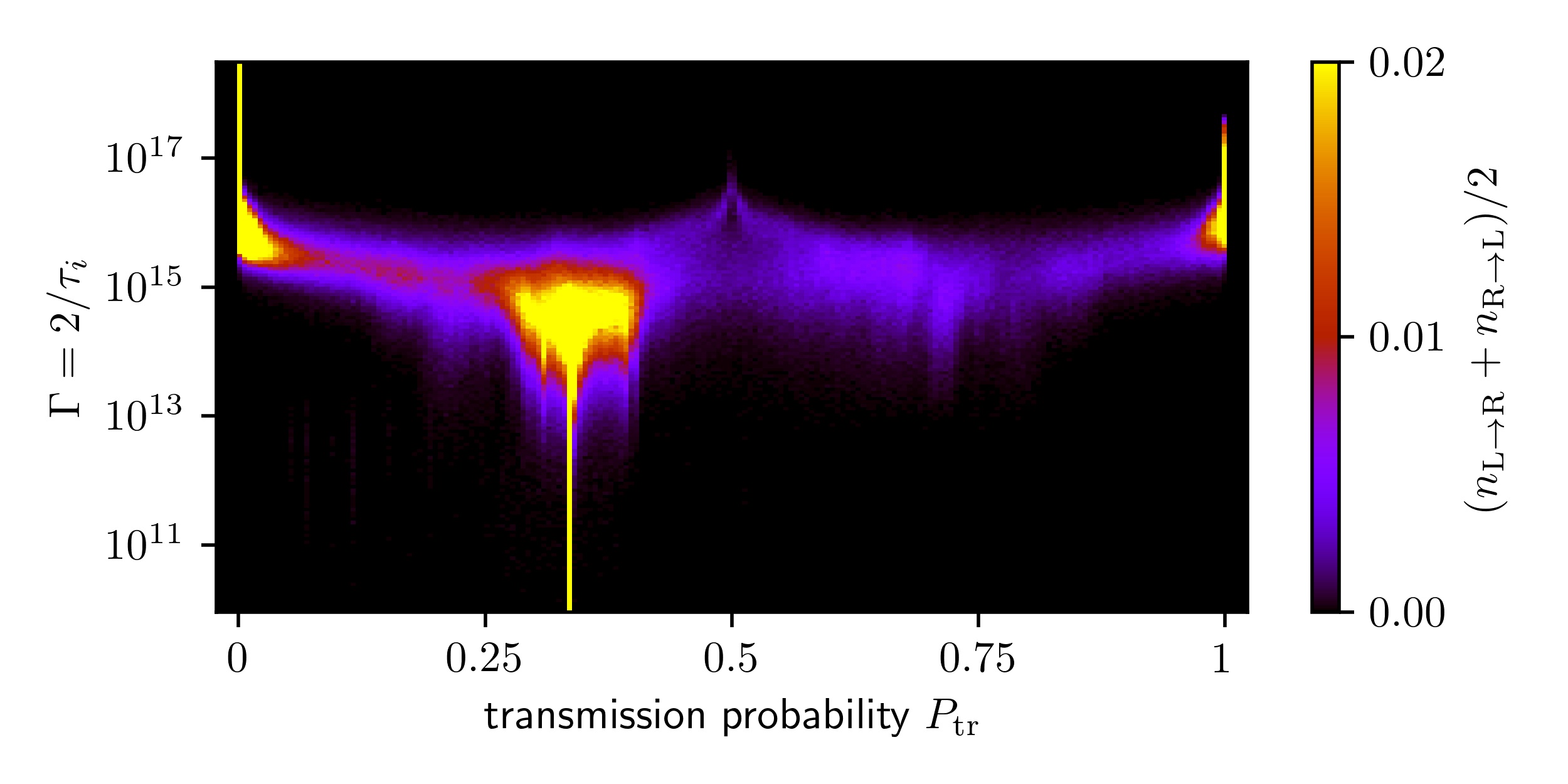
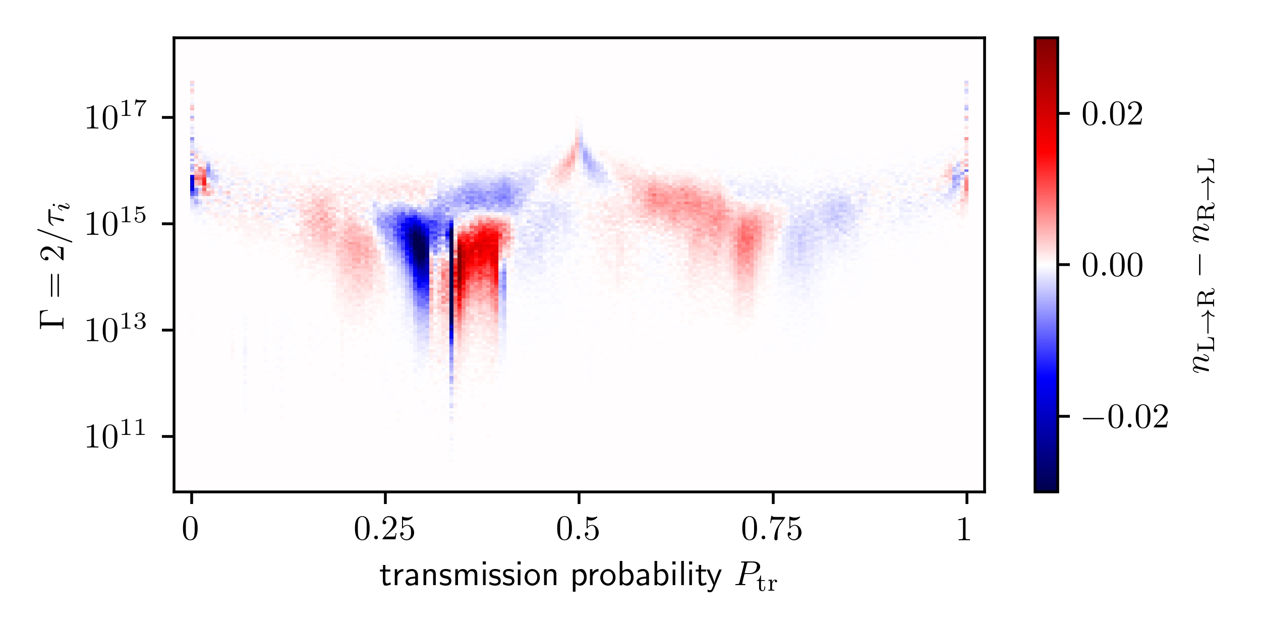
We use the stochastic approach to illustrate the transition between the different regimes of electron transport. Figure 5a shows the distribution of the transmission probability of device A as a function of averaged over the two travel directions. For , in the unitary quantum regime, the probability for is peaked at , indicating that individual electrons leave the system in a state that is a superposition of being located in the port of origin and in the other port. For — in the transition regime — the distribution varies rapidly with changing and superpositions of any composition are found. For , in the classical regime, the distribution is peaked at and . Each individual electron is either reflected or transmitted by the device. States with a coherent superposition are no longer possible. Finally, for , the probability has a single peak at . This is due to the quantum Zeno effect [39]: the scattering rate is so high that electrons cannot pass through the device. Figure 5b shows the difference of the distributions belonging to the two directions. We draw attention to three features of the graph. First, the largest difference is observed at , the most probable transmission in the case without scattering. This implies that electrons traveling in one of the directions are indeed more frequently scattered inelastically than electrons traveling in the opposite direction. Second, positive differences are found at higher values of than negative differences. This implies nonreciprocity of the average transmission. Finally, the nonreciprocity is easily observed when approaching the classical regime: the peak at is negative and the peak at is positive. Therefore, more electrons are transmitted when originating from and more electrons are reflected when originating from . The stochastic time evolution of single electrons provides an understanding of the dynamics in the transition regime and confirms the reasoning that the observed nonreciprocity is caused by direction dependent decoherence.
IV The charge-separated steady state
In the previous two sections we have shown that nonreciprocal transport is present when electrons are described as wave packets. How are these results to be interpreted in the larger framework of transport theory which refers to the states in the vicinity of thermal equilibrium, characterized by a well-defined constant temperature on the nanoscopic scale? In equilibrium, electron wave packets may occur as fluctuations, e.g. by the thermally excited release of electrons from trapping sites. Indeed, the success of the semi-classical theory of electron transport shows unambiguously that physically relevant thermal excitations from the Fermi sea are wave packets of finite size. According to Onsager’s reciprocity relations, such fluctuations always relax back to the equilibrium state, which is the starting point of both the semi-classical and quantum theories of linear transport [16, 17, 18, 19, 20, 22, 23, 24, 25, 26, 27].
For the devices presented here, however, these fluctuations do not necessarily relax back into the standard thermal equilibrium state. Wave packets that occur as fluctuations around the thermal equilibrium may be sorted by the devices as discussed in Sections II and III and therefore lead to a charge accumulation at one side of the device. To demonstrate this numerically, we employ a minimized version of the models used in the previous sections. This system, sketched in Fig. 6, is given by a chain of 9 sites with the site basis vectors . A ramp-shaped electric potential is applied to sites , and to break the symmetry. The potential at the remaining sites is zero (see Appendix C.3).
Because the existence of wave packets is crucial, we modify the jump operators in Eq. 1 to now describe the capture of the electron at site and the subsequent release from this site into the state which is a wave packet. The wave packet is generated at with momentum which is determined by the recoil of the trap which now carries the momentum . For the momentum the value is used because it is in the range of momenta for which relevant interference effects take place in the device. The following results do not depend on the choice of in a qualitative manner. The corresponding jump operators are non-hermitean, with the Lindblad equation
| (3) |
Fig. 7a shows the time-dependent probability for the electron being in the left, right or central part of the chain, as derived from the dynamics of Eq. 3 with wave packets being generated at site with the rate . The initial state is given by the thermal density matrix , where are the eigenstates of with energy and . As shown by Fig. 7, this state is not stable, but evolves into a steady state with a lower entropy and partial charge separation between the two ports. The chain spontaneously develops a charge imbalance with net current zero. The - characteristic contains therefore a new, constant term,


| (4) |
The central assumption underlying Onsager’s reciprocity relations is therefore not satisfied in the case discussed. Furthermore, this - characteristic suggests a net current to flow in case the chain is bent into a ring, with the left and right chain ends being shorted. Figs. 7b and 7c, showing the results of the corresponding calculation, reveal that a circulating persistent current is indeed generated for , corresponding to the transition regime. This persistent current induces a corresponding magnetic moment. Notably, this steady-state current vanishes for very small and large rates . This behavior is analogous to the behavior of the wave-packet transmission probabilities, which are nonreciprocal only in a well-defined window of the decoherence rate.
To investigate whether the asymmetric device geometry is responsible for the charge separation and the circulating current, the state evolution of a chain and a ring with symmetric potential barriers were calculated. As expected, these displayed no charge separation (Fig. 14). With hermitean jump operators (Eq. 1), also no charge separation is found in the long time limit, even when starting from a non-equilibrium density matrix (Fig. 15). This underlines the importance of the existence of wave packets with non-zero momentum for the charge-separated steady state. To explore whether the unconventional steady state generated by Eq. 3 is destroyed by other inelastic processes that may exist and drive the system towards standard equilibrium, we have also added such processes to the master equation and found that the novel steady state persists also in this case (see Appendix C.3).
V Discussion and Outlook
The transition between the quantum and classical worlds is of intense interest. It harbors fundamental questions concerning the appropriate description of decoherence and the measurement process. The devices we have discussed operate precisely at the border between these two worlds, because they utilize a small number of random phase-breaking events that interrupt the otherwise unitary evolution of wave packets. Our work shows that in the unitary regime, electrons flow through devices with nonreciprocal velocities if the devices are shaped with appropriate asymmetries. Our results have been obtained by using several assumptions and are only valid in those cases in which these assumptions apply. In particular, we have considered idealized model systems following a strict single particle picture with perfect screening and without disorder. For those real materials that may be influenced by the phenomena described, e.g. lightly doped semiconductors, nothing more than nanostructuring a film is required in order to achieve rectification as described by Eq. 4. The optical analog of such devices is presented in [40]. The effects presented differ from the nonreciprocal behavior of standard diodes [41], quantum rings [42], quantum dots [43], chiral structures [44], Weyl semimetals [45], noncentrosymmetric superconductors [46], and multiferroics [47]. In those cases, the nonreciprocity is achieved by nonlinear, higher-order processes; the voltage for vanishes, . In those cases, also no unconventional steady state exists besides the standard thermal equilibrium.
In conclusion, we have presented a device concept in which nonreciprocal matter transport emerges when the inverse decoherence rate is of the order of the characteristic time for unitary transport through the device. This situation exists exactly in the transition regime between quantum physics and classical physics. The nonreciprocal matter transport is expected to occur not only in top-down patterned devices but also in molecules with appropriate asymmetric structures and in crystals with suitable lattices. The phenomena found are explorable by experiments on mesoscopic electronic or photonic devices. The described mechanism underlying nonreciprocal, directed dynamics could even be responsible for the proper operation of biomolecules and thus for living systems.
VI Acknowledgement
The authors gratefully acknowledge useful discussions with A. Alavi, A. Brataas, T. Kopp, P. Schneeweiss, and support by L. Pavka, T. Whittles, and the computer service group of MPI-FKF. J. Mannhart acknowledges support by the Center for Integrated Quantum Science and Technology (IQST). The numerical calculations were performed using the Kwant [48] and QuTIP [49, 50] Python packages.
basd asd asd asd asdas dasd asd asda sdasd asd asd asd basd asd asd asd asdas dasd asd asda sdasd asd asd asd
References
- Bohr [1935] N. Bohr, Can quantum-mechanical description of physical reality be considered complete? Phys. Rev. 48, 696 (1935).
- Heisenberg [2000] W. Heisenberg, Physik und Philosophie. (Hirzel, Stuttgart, 2000).
- Wheeler and Zurek [1983] J. Wheeler and W. Zurek, Quantum Theory and Measurement (Princeton University Press, Princeton, 1983).
- Von Neumann [2013] J. Von Neumann, Mathematische Grundlagen der Quantenmechanik, Vol. 38 (Springer-Verlag, 2013).
- Zeh [1970] H. D. Zeh, On the interpretation of measurement in quantum theory, Foundations of Physics 1, 69 (1970).
- Zurek [2003] W. H. Zurek, Decoherence, einselection, and the quantum origins of the classical, Rev. Mod. Phys. 75, 715 (2003).
- Everett [1957] H. Everett, Relative state formulation of quantum mechanics, Rev. Mod. Phys. 29, 454 (1957).
- Ghirardi et al. [1986] G. C. Ghirardi, A. Rimini, and T. Weber, Unified dynamics for microscopic and macroscopic systems, Phys. Rev. D 34, 470 (1986).
- Gisin [1984] N. Gisin, Quantum measurements and stochastic processes, Phys. Rev. Lett. 52, 1657 (1984).
- Diosi [1988] L. Diosi, Quantum stochastic processes as models for state vector reduction, Journal of Physics A: Mathematical and General 21, 2885 (1988).
- Dalibard et al. [1992] J. Dalibard, Y. Castin, and K. Molmer, Wave-function approach to dissipative processes in quantum optics, Phys. Rev. Lett. 68, 580 (1992).
- Carmichael [1992] H. Carmichael, An open systems approach to quantum optics (Springer Science, 1992).
- Daley [2014] A. J. Daley, Quantum trajectories and open many-body quantum systems, Advances in Physics 63, 77 (2014), https://doi.org/10.1080/00018732.2014.933502 .
- Molmer et al. [1993] K. Molmer, Y. Castin, and J. Dalibard, Monte Carlo wave-function method in quantum optics, J. Opt. Soc. Am. B 10, 524 (1993).
- Haag [2013] R. Haag, On the sharpness of localization of individual events in space and time, Foundations of Physics 43, 1295 (2013).
- Landauer [1957] R. Landauer, Spatial variation of currents and fields due to localized scatterers in metallic conduction, IBM Journal of Research and Development 1, 223 (1957).
- Büttiker [1988] M. Büttiker, Absence of backscattering in the quantum Hall effect in multiprobe conductors, Phys. Rev. B 38, 9375 (1988).
- Drude [1900] P. Drude, Zur Elektronentheorie der Metalle, Annalen der Physik 306, 566 (1900).
- Sommerfeld [1928] A. Sommerfeld, Zur Elektronentheorie der Metalle auf Grund der Fermischen Statistik, Zeitschrift für Physik 47, 1 (1928).
- Kubo et al. [1957] R. Kubo, M. Yokota, and S. Nakajima, Statistical-mechanical theory of irreversible processes. ii. response to thermal disturbance, Journal of the Physical Society of Japan 12, 1203 (1957), https://doi.org/10.1143/JPSJ.12.1203 .
- Imry [2002] Y. Imry, Introduction to mesoscopic physics (Oxford University Press on Demand, 2002).
- Gefen et al. [1984] Y. Gefen, Y. Imry, and M. Y. Azbel, Quantum oscillations and the Aharonov-Bohm effect for parallel resistors, Phys. Rev. Lett. 52, 129 (1984).
- Stern et al. [1990] A. Stern, Y. Aharonov, and Y. Imry, Phase uncertainty and loss of interference: A general picture, Phys. Rev. A 41, 3436 (1990).
- Blanter and Büttiker [2000] Y. Blanter and M. Büttiker, Shot noise in mesoscopic conductors, Physics Reports 336, 1 (2000).
- Hansen et al. [2001] A. E. Hansen, A. Kristensen, S. Pedersen, C. B. Sørensen, and P. E. Lindelof, Mesoscopic decoherence in Aharonov-Bohm rings, Phys. Rev. B 64, 045327 (2001).
- Beenakker and van Houten [1991] C. Beenakker and H. van Houten, in Semiconductor Heterostructures and Nanostructures, Solid State Physics, Vol. 44, edited by H. Ehrenreich and D. Turnbull (Academic Press, 1991) pp. 1–228.
- Washburn and Webb [1992] S. Washburn and R. A. Webb, Quantum transport in small disordered samples from the diffusive to the ballistic regime, Reports on Progress in Physics 55, 1311 (1992).
- Lindblad [1976] G. Lindblad, On the generators of quantum dynamical semigroups, Commun.Math. Phys. 48, 119 (1976).
- Onsager [1931] L. Onsager, Reciprocal relations in irreversible processes. I. Phys. Rev. 37, 405 (1931).
- Tokura and Nagaosa [2018] Y. Tokura and N. Nagaosa, Nonreciprocal responses from non-centrosymmetric quantum materials, Nature Communications 9, 3740 (2018).
- Mannhart [2018] J. Mannhart, Non-reciprocal interferometers for matter waves, Journal of Superconductivity and Novel Magnetism 31, 1649 (2018).
- Mannhart and Braak [2019] J. Mannhart and D. Braak, Lossless currents at high temperatures, Journal of Superconductivity and Novel Magnetism 32, 17 (2019).
- Bredol [2021] P. Bredol, Nonreciprocity of the wave-packet scattering delay in ballistic two-terminal devices, Phys. Rev. B 103, 035404 (2021).
- Jin et al. [2020] T. Jin, M. Filippone, and T. Giamarchi, Generic transport formula for a system driven by markovian reservoirs, Phys. Rev. B 102, 205131 (2020).
- Jin et al. [2021] T. Jin, J. S. Ferreira, M. Filippone, and T. Giamarchi, Exact description of quantum stochastic models as quantum resistors, arXiv 2106.14765 (2021).
- Aharonov and Bohm [1959] Y. Aharonov and D. Bohm, Significance of electromagnetic potentials in the quantum theory, Phys. Rev. 115, 485 (1959).
- Webb et al. [1985] R. A. Webb, S. Washburn, C. P. Umbach, and R. B. Laibowitz, Observation of Aharonov-Bohm oscillations in normal-metal rings, Phys. Rev. Lett. 54, 2696 (1985).
- Ashcroft and Mermin [1976] N. W. Ashcroft and N. D. Mermin, Solid State Physics (Holt, Rinehart and Winston, New York, 1976).
- Misra and Sudarshan [1977] B. Misra and E. C. G. Sudarshan, The Zeno’s paradox in quantum theory, Journal of Mathematical Physics 18, 756 (1977), publisher: American Institute of Physics.
- Braak and Mannhart [2020] D. Braak and J. Mannhart, Fermi’s golden rule and the second law of thermodynamics, Foundations of Physics 50, 1509 (2020).
- Brillouin [1950] L. Brillouin, Can the rectifier become a thermodynamical demon? Phys. Rev. 78, 627 (1950).
- Leturcq et al. [2006] R. Leturcq, D. Sánchez, G. Götz, T. Ihn, K. Ensslin, D. C. Driscoll, and A. C. Gossard, Magnetic field symmetry and phase rigidity of the nonlinear conductance in a ring, Phys. Rev. Lett. 96, 126801 (2006).
- Marlow et al. [2006] C. A. Marlow, R. P. Taylor, M. Fairbanks, I. Shorubalko, and H. Linke, Experimental investigation of the breakdown of the Onsager-Casimir relations, Phys. Rev. Lett. 96, 116801 (2006).
- Rikken et al. [2001] G. L. J. A. Rikken, J. Fölling, and P. Wyder, Electrical magnetochiral anisotropy, Phys. Rev. Lett. 87, 236602 (2001).
- Morimoto and Nagaosa [2016] T. Morimoto and N. Nagaosa, Chiral anomaly and giant magnetochiral anisotropy in noncentrosymmetric Weyl semimetals, Phys. Rev. Lett. 117, 146603 (2016).
- Saito et al. [2016] Y. Saito, T. Nojima, and Y. Iwasa, Highly crystalline 2d superconductors, Nature Reviews Materials 2, 16094 (2016).
- van Aken et al. [2007] B. B. van Aken, J.-P. Rivera, H. Schmid, and M. Fiebig, Observation of ferrotoroidic domains, Nature 449, 702 (2007).
- Groth et al. [2014] C. W. Groth, M. Wimmer, A. R. Akhmerov, and X. Waintal, Kwant: a software package for quantum transport, New Journal of Physics 16, 063065 (2014).
- Johansson et al. [2012] J. Johansson, P. Nation, and F. Nori, Qutip: An open-source python framework for the dynamics of open quantum systems, Computer Physics Communications 183, 1760 (2012).
- Johansson et al. [2013] J. Johansson, P. Nation, and F. Nori, Qutip 2: A python framework for the dynamics of open quantum systems, Computer Physics Communications 184, 1234 (2013).
- Schäpers [2008] T. Schäpers, Phase-coherent states, in Nanotechnology, edited by R. Waser (Wiley-VCH, 2008) Chap. 1, pp. 1–35.
Appendix A Videos
Videos of selected time evolutions. Fig. 8 shows the starting configuration of the time evolution of a wave packet passing a device unitarily with a transverse asymmetry that is shown in the videos. Fig. 9 shows the corresponding configuration for an asymmetric Aharonov-Bohm ring. Fig. 10 shows the starting image of the video display the wave packet propagating across an asymmetric Aharonov-Bohm ring interrupted by collapse processes. The videos are available at https://fkf.mpg.de/mannhart.





Appendix B Time-dependent wave packets and currents
In this part of the supplement we show that the time-dependent currents of wave packets are not reciprocal in a two-terminal device. Nevertheless, the total transported charge is reciprocal in the long time limit. Unitary evolution yields therefore reciprocal transport probabilities independent from the shape of the electronic wave function in the steady state.
We consider a one-dimensional wire along the -axis on a two-dimensional substrate with a local potential confined to a finite region in the /-plane and a homogeneous magnetic field perpendicular to the plane. The wire is attached to charge reservoirs (ports) on the left and the right side with chemical potentials and , respectively. The single-particle Hamiltonian reads then (with electron charge and mass )
| (5) |
The potential confines the electrons to the wire, whereas the potential for . With the choice , we can approximate the eigenfunctions of Eq. 5 in the wire outside the interaction region by plane waves with The transversal quantum number is denoted by . We assume for simplicity that the energy of does not depend on it.
The asymptotic form of for reads in general
| (6) | ||||
| (7) |
with the normalization factor , where is the length of the wire. A wave function with energy is in general a superposition of incoming waves from the left with amplitudes and from the right with amplitudes . Both waves are scattered in the region of , with direction-dependent transmission and reflection amplitudes , , . The S-matrix of the system reads
| (8) |
Unitarity of requires:
| (9) | ||||
| (10) |
In the steady state, the current of state injected from the left reservoir at some point reads
| (11) |
with the electron velocity . The total current injected from the left and passing the point is
| (12) |
Here, is the number of transversal channels and is the one-dimensional density of states per channel. It follows that
| (13) |
The total current at contains a contribution from electrons which are reflected at the central region and those transmitted from the right reservoir:
| (14) |
To obtain the linear response for stationary states, one averages over . Using Eq. 10 we obtain [51],
| (15) | |||
| (16) |
where () are the voltages of the left (right) reservoir. One sees that because of Eq. 10, the coherent linear response for stationary states is reciprocal and if .
Now we consider wave packets instead of the time-independent stationary eigenstates of the system, e.g., of Gaussian form. At the initial time , the packet is localized in the left part of the wire around with momentum expectation value , moving to the right.
| (17) | ||||
| (18) |
If the packet is sufficiently narrow, the coefficients may be computed using the asymptotic expressions given in Eq. 6 and Eq. 7 to obtain
| (19) | ||||
| (20) | ||||
| (21) |
The state given in Eq. 18 is time-dependent. The associated current at some point on the right side of the interacting region reads at time
| (22) |
where denotes the real part of . Now
| (23) |
and to compute we may use the asymptotics of . This yields
| (24) |
with . We consider now a second initial state obtained from by reflection of at the origin: , centered around .
| (25) | ||||
| (26) |
The state has average momentum and moves to the left. The coefficients read
| (27) | ||||
| (28) |
For this state, we calculate the current at a time and at the point . The result is
| (29) |
with . By comparing Eq. 24 and Eq. 29, one sees that the currents are reflection-symmetric, i.e., , if and . This follows from the reflection symmetry of the Hamiltonian
| (30) |
because then
| (31) |
However, if Eq. 30 is not satisfied, we have in general
| (32) |
The left and right transmission and reflection coefficients differ by phase factors, which are allowed by the unitarity of the S-matrix . If the , do not vanish, it follows , i.e., the time-dependent currents are not reciprocal.
Nevertheless, the total charge transported from the left to the right over a sufficiently long time equals the total charge flowing from the right to the left, so that the steady state has reciprocal transport characteristics, in accordance with the result Eq. 16, which follows from Eq. 10. The charge of initial state flowing through the point in the time interval to the right is given by
| (33) |
whereas the charge of state flowing to the left through point reads
| (34) |
The limit exists because we consider an open system without periodic boundary conditions. Thus the electron may pass the point and never come back - otherwise would be either zero or infinity. Reciprocity of the steady state corresponds to . Because
| (35) |
where denotes the principal part, we obtain
| (36) |
and
| (37) |
Using the identity , which follows from the unitarity of , one may show that the integrands of Eq. 36 and Eq. 37 are the same. Therefore
| (38) |
as anticipated.
Appendix C Numerical implementation
C.1 Lindblad formalism
The numerical implementation starts with the tight-binding Hamiltonian:
| (39) |

where denotes the hopping energy, a pair of neighboring sites and , the creation and annihilation operators on site . In the following, we confine ourselves to the single-particle subspace. For we take , corresponding to typical dwelling times of several in the device. The lattice defines the system geometry and size. The following paragraphs refer to the systems used in Sections II and III. The implementation details of the minimized system shown in Section IV can be found in Section C.3 of this appendix. The leads are implemented as long lines. The systems contain up to 5065 sites to ensure that during the observation time the wave packets do not return back into to device. Gaussian wave packets with and and , where is the lattice constant of , serve as initial wave functions for the devices A, B, D and C, respectively. We start from the density matrix of a pure state where is either a right-moving wave packet placed in the left port , , or a left-moving packet, located in the right port . is then numerically evolved with the Lindblad equation Eq. 1 to compute the quantities and as function of . For the devices A, B, and D we have used nine different scattering centers located at the sites indicated in Fig. 11 with the same coupling . For the device C we regard the entire lower interferometer arm as a scattering center. In this case, there is only one projection operator onto the subspace spanned by all sites in the lower interferometer arm. The layout of the devices is further illustrated in Fig. 12.
C.2 Monte-Carlo wave functions
As in Eq. 22, we calculate the time-dependent probability currents at sites and to obtain the total transmitted and reflected charges as in Eq. 33 and Eq. 34. The time is discretized in steps of width to obtain an adequate temporal resolution in the time integrals of the currents and the dynamical collapse events.
The collapse events are computed in the following way: A collapse occurs with probability per unit time, the rate constant of the corresponding Poisson process is then , where is the average time between collapses occurring at times and . The rate constant is proportional to the coupling between the electron and the localized degree of freedom with which it interacts inelastically. The inelastic event itself is treated like a measurement process: The electron with wave function becomes localized (positive measurement result) and acquires one of the wave functions at time with probability . The index runs over the inelastic scattering centers as depicted in Fig. 11.
In case of a negative measurement result, the state at is the projection of onto the orthogonal complement of the sum of all . This happens with probability . From the time onwards, the state develops according to the time-dependent Schrödinger equation until the next collapse event at time , where the wave function changes again discontinuously.
For Figs. 5, 13 we use the following collapse scenario: , being one of the nine lattice points . In case of a negative measurement, the wave function is projected onto the orthogonal complement of the span of all nine .
We demonstrate now that averaging over the stochastic trajectories obtained in this way yields the same result for the reduced density matrix as computed via the Lindblad equation Eq. 1. First, we consider the case of a single scattering center at site . Let’s assume that for the -th trajectory the wave function at time is . At time , the wave function reads then
| (40) |
This entails the following mixed density matrix at time belonging to the -th trajectory up to time (neglecting terms of order ),
| (41) |
which yields the following equation for the derivative of at time ,
| (42) |
The average over all trajectories therefore satisfies the same differential equation for all times, from which we obtain the Lindblad equation Eq. 1 for a single scattering center with the identification . The generalization to several scattering centers is straightforward.
The presented stochastic unraveling of the Lindblad equation is not unique. Another stochastic process, equivalent to Eq. 1, considers only positive measurements, the “quantum jump” projects the wave function with probability always onto one of the , but never onto . To account for null measurements, the deterministic evolution of between collapse events proceeds not with the hermitean Hamiltonian but with the non-hermitean operator . For this, an additional normalization of during the evolution is required because does not conserve the norm of the wave function [12]. The corresponding master equation for reads then
| (43) |
The accuracy of the calculations of the unitary dynamics in our numerical implementation is limited by the finite size of the leads, which sets an upper bound to the observation time due to recurrence of the waves after they have been reflected by the lead ends. In our case, .
The statistical accuracy of the collapse dynamics obviously increases with the number of sampled trajectories. In the calculations, a minute fraction of trajectories had to be discarded because accumulation of numerical discretization errors led to division-by-zero errors or minute negative probabilities. For Fig. 5, trajectories were used for each transmission map, trajectories were discarded. The same discretization errors cause the calculated total probability of all trajectories to deviate from 1. On average, the probability conservation violation equals . For of the trajectories it is better than , the largest violation being . A third systematic error concerns the fact that at the wave function is not completely zero inside the device, such that , where , are the charges in the contacts. Less than of the trajectories leave a residual charge (all numbers referring to the calculations shown in Fig. 5).
C.3 Minimized model used to calculate steady states
The calculations of steady states in Section IV were done using the smaller tight-binding system sketched in Fig. 6. The Hamiltonian of this system is given by
| (44) |
where the tight-binding lattice is given by , are again the pairs of neighboring sites. Sites that are connected by solid lines in Fig. 6 are of course neighbors. In the ring configuration used to demonstrate the existence of persistent currents, the sites at the left and right ends of the chain are nearest neighbors as well. The and are the creation and annihilation operators on site and is the electric potential at site . The asymmetric potential barrier used for the calculations shown in the main text is given by
| (45) |
The symmetric potential barrier used in Fig. 14 is given by
| (46) |
The two wave packet states used for the jump operators are given by
| (47) |
The electrical current associated with a density operator is calculated using the velocity operator ,
| (48) | ||||
| (49) |
with the elementary charge and the 1D carrier density and the position operator . The density is chosen such that the chain contains one carrier with the lattice constant .
The thermal relaxation processes mentioned in the last paragraph of Section IV are implemented by additional jump operators , where is the eigenstate of the Hamiltonian with energy . The corresponding rates are given by . The resulting Lindblad equation reads
| (50) |
Fig. 16 shows the temporal behavior of the charge imbalance for the chain with the thermalizing jump operators. The initial state is the unique steady state of Eq. 50 without the impurity dissipators . It is clear that the novel steady state persists even with these relaxation processes.
Appendix D Further figures
Figures 12, 13 and 14 further illustrate the time evolution of the electron waves in several devices.
Figure 14 illustrates that the time evolution of the open and closed chains (Fig. 6) for various degrees of asymmetry. As shown by the figure, the device asymmetry is mandatory for charge separation or persistent currents to occur. Figure 15 illustrates for the case of a device with longitudinal asymmetry that a a hermitean jump-operator does not generate a charge-separated steady-state.
Figure 16 shows that a charge-separated steady state is generated by the open 9-site chain even if additional jump operators that drive the system to thermal equilibrium are present in the Lindblad master equation.


