Magnon polarons in the spin Peltier effect
Abstract
We report the observation of anomalous peak structures induced by hybridized magnon-phonon excitation (magnon polarons) in the magnetic field dependence of the spin Peltier effect (SPE) in a Lu2Bi1Fe4Ga1O12 (BiGa:LuIG) with Pt contact. The SPE peaks coincide with magnetic fields tuned to the threshold of magnon-polaron formation, consistent with the previous observation in the spin Seebeck effect. The enhancement of SPE is attributed to the lifetime increase in spin current caused by magnon-phonon hybridization in BiGa:LuIG.
I I. INTRODUCTION
Magnetoelastic coupling (MEC), the interaction between spin waves (magnons) and lattice waves (phonons), was first investigated more than half a century ago Akhiezer1959SovPhysJETP ; Kittel1958PhysRev ; Kaganov1959SovPhysJETP and has renewed attention in spintronics Dreher2012PRB ; Ruckriegel2014PRB ; Kamra2015PRB ; Ogawa2015PNAS ; Shen2015PRL ; Takahashi2016PRL ; Kikkawa2016PRL ; Graczyk2017PRB ; Flebus2017PRB ; Cornelissen2017PRB ; Bozhko2017PRL ; Hashimoto2017NatCommun ; Man2017PRB ; Wang2018APL ; Holanda2018NatPhys ; Streib2018PRL ; Schmidt2018PRB ; Shan2018APL ; Hayashi2018PRL ; Shen2019PRB ; Rameshti2019PRB ; Simensen2019PRB ; Sivarajah2019JAP ; An2019 ; Ramos2019NatCommun ; Thingstad2019PRL ; Streib2019PRB . By the MEC, magnons and phonons, in the vicinity of the crossings of their dispersion relations, are hybridized into quasiparticles called magnon polarons that share mixed magnonic and phononic characters Kamra2015PRB ; Shen2015PRL ; Kikkawa2016PRL ; Flebus2017PRB ; Cornelissen2017PRB ; Schmidt2018PRB ; Shan2018APL ; Hayashi2018PRL ; Shen2019PRB ; Rameshti2019PRB ; Simensen2019PRB ; Thingstad2019PRL ; Streib2019PRB ; Sivarajah2019JAP ; An2019 ; Ramos2019NatCommun . Magnon polarons can convey spin information with velocities close to those of phonons, much faster than the magnon velocities in the dipolar magnon regime Ogawa2015PNAS ; Shen2015PRL ; Bozhko2017PRL ; Hashimoto2017NatCommun . Besides, thanks to the long-lived phononic constituent, magnon polarons may have longer lifetimes than pure magnons and can enhance the spin-current related phenomena, such as the spin Seebeck effect Kikkawa2016PRL ; Flebus2017PRB ; Cornelissen2017PRB ; Wang2018APL ; Schmidt2018PRB ; Shan2018APL ; Shen2019PRB ; Ramos2019NatCommun and spin pumping Hayashi2018PRL .
The spin Seebeck effect (SSE) SSE_review refers to the generation of a spin current () as a result of a temperature gradient () in magnetic materials with metallic contacts. In the SSE, a magnon flow in a magnet is converted into a conduction-electron spin current at the magnet/metal interface and detected as a transverse electric voltage via the inverse spin Hall effect (ISHE) SHE_Hoffman ; SHE_Sinova . Recent experiments have revealed that small asymmetric peak structures appear in magnetic field-dependent (longitudinal) SSE voltages, which are interpreted as the enhanced spin current caused by the long-lived magnon-polaron formation Kikkawa2016PRL ; Flebus2017PRB ; Cornelissen2017PRB ; Wang2018APL ; Schmidt2018PRB ; Ramos2019NatCommun . The peaks show up at magnetic fields at which the phonon dispersion curves become tangential to the magnon dispersion, i.e., when the magnon and phonon frequencies , wave numbers , and group velocities become the same. Under these “touching” conditions, the magnon and phonon modes can be coupled over the largest volume in -space (see Fig. 2 of Ref. Flebus2017PRB ), such that the phase space portion over which the lifetimes of spin current are enhanced with respect to the uncoupled situation is maximal, leading to the enhancement of the SSE Kikkawa2016PRL ; Flebus2017PRB .
In this study, we explore the magnon-polaron features in the spin Peltier effect (SPE), the reciprocal effect of the SSE, referring to the heat-current generation as a result of a spin current Flipse2014PRL ; Basso2016PRB ; Daimon2016NatCommun ; Daimon2017PRB ; Uchida2017PRB ; Ohnuma2017PRB ; Itoh2017PRB ; Seki2018APL ; Yagmur2018JPhysD ; Sola2019SciRep ; Daimon2019 . According to the Boltzmann transport theory Flebus2017PRB , the bulk spin-transport coefficients for the SSE and SPE are linked by the Onsager reciprocal relation, so that similar small magnon-polaron peaks may show up also in the SPE. However, experimentally measured quantities are not the bulk transport coefficients, and thereby whether or not the hybridization peaks appear in the SPE is a nontrivial problem, which should be addressed experimentally. Nevertheless, there has been an issue to explore it; a measured SPE signal itself is usually very small. When measuring the SPE electrically by a thermocouple, the detected voltages are times smaller than the typical SSE electric voltages measured via the ISHE Flipse2014PRL ; Itoh2017PRB ; SSE_review . Here, to overcome this issue, we use a Bi- and Ga-substituted lutetium iron garnet Lu2Bi1Fe4Ga1O12 (BiGa:LuIG) film that exhibits large magnon-polaron peaks in SSE voltages [eight times greater than conventional Y3Fe5O12 (YIG) films at room temperature, mainly due to its reduced magnon lifetime compared to YIG] Ramos2019NatCommun . By careful measurements, magnon polarons turned out to manifest as peaks in magnetic field-dependent SPE signals, as with the SSE. Our results provide an important step towards a complete physical picture of magnon-polaron transport in magnetic insulators.
II II. EXPERIMENTAL PROCEDURE
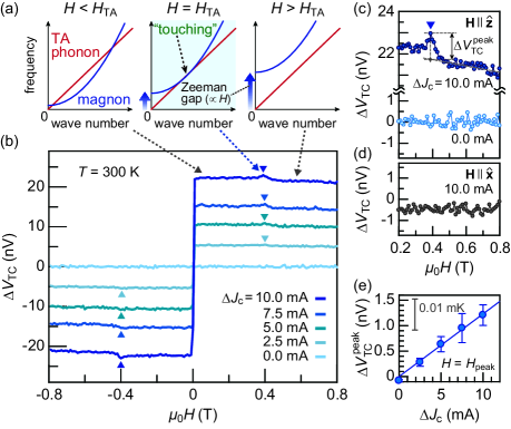
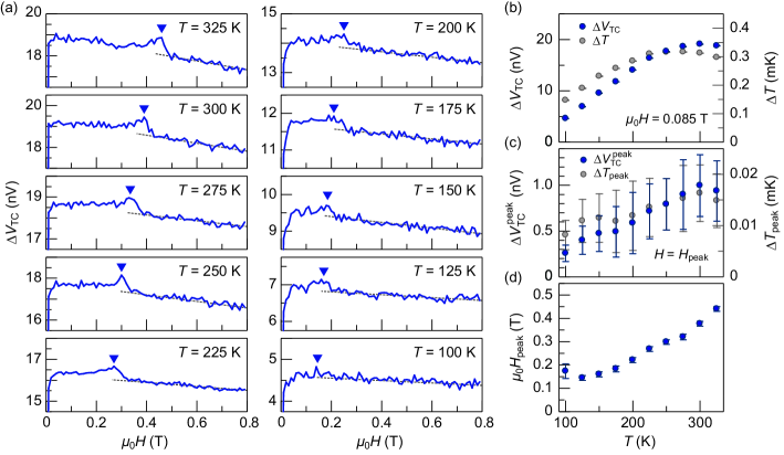
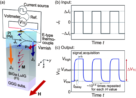
Figure 1(a) shows a schematic of the SPE in a paramagnetic metal (PM)/ferrimagnetic insulator (FI) junction, where the PM (FI) is Pt (BiGa:LuIG) in the present study. The SPE appears as a result of a spin current induced by the spin Hall effect (SHE) in PM Flipse2014PRL ; Daimon2016NatCommun ; Daimon2017PRB ; Itoh2017PRB . When a charge current is applied to the PM, a spin current is generated and creates a nonequilibrium spin accumulation at the PM/FI interface SHE_Hoffman ; SHE_Sinova ; Flipse2014PRL ; Daimon2016NatCommun ; Daimon2017PRB ; Itoh2017PRB
| (1) |
where is the spin Hall angle of PM. By the interfacial spin-exchange coupling, causes a nonequilibrium magnon creation or annihilation scattering; when is parallel (antiparallel) to the equilibrium magnetization () in FI, the number of magnons in FI is increased (decreased). This process accompanies a heat flow between the PM/FI and thereby modulates the system temperature. The SPE-induced temperature modulation satisfies the following relation Daimon2016NatCommun ; Daimon2017PRB ; Itoh2017PRB
| (2) |
We prepared a Pt()-strip/BiGa:LuIG() bilayer film, where the numbers in parentheses represent the thickness. The single-crystalline BiGa:LuIG (100) film was grown by liquid phase epitaxy on Gd3Ga5O12 (GGG) (100) substrate (a rectangular shape). Before the Pt deposition, the BiGa:LuIG/GGG was cleaned with acetone in an ultrasonic bath and then cleaned with so-called Piranha etch solution (a mixture of H2SO4 and H2O2 at a ratio of 1:1) to remove organic matter attached to the BiGa:LuIG surface Kikkawa2017PRB . Subsequently, the Pt strip was sputtered on the BiGa:LuIG (100) surface by DC sputtering in an Ar atmosphere. The length and width of the Pt strip are and , respectively.
To measure the SPE-induced temperature modulation, we follow the experimental method shown in Ref. Itoh2017PRB . We first attached an E-type thermocouple (TC) on top of the middle of the Pt strip by pasting GE-varnish thinly [Fig. 1(a)]. Hence, the TC wire is electrically insulated from but thermally well connected to the Pt layer. Then, the TC wires were connected to a nanovoltmeter (Keithley 2182A) via conductive wires, while the ends of the 2-mm-long Pt strip were connected to a current source (Keithley 6221). The magnetic field (with magnitude ) was applied in the film plane and perpendicular to the Pt strip, i.e., in Fig. 1(a), except for the control experiment shown in Fig. 3(d), where . For the electric detection of the SPE, it is important to exclude the large contribution from the Joule heating of the Pt layer Daimon2016NatCommun ; Daimon2017PRB ; Itoh2017PRB . To this end, we applied a square-wave charge current with amplitude [Fig. 1(b)] and measured the TC voltage that responds to the change in the polarity, , where () represents the value when [see Fig. 1(c)] Itoh2017PRB . Here, the Joule-heating-induced temperature modulation () takes a constant value in time [ in Fig. 1(c)] and does not overlap in , enabling the electric detection of the SPE. The TC voltage () was recorded after the time delay of Itoh2017PRB and accumulated by repeating the process of the -polarity change from to times for each point [see Fig. 1(c)] to improve the signal-to-noise ratio and discern very tiny magnon-polaron signals (as small as sub-nanovolts) polarity-change . can be converted into the corresponding temperature value by the Seebeck coefficient of the E-type TC . Further details on the measurements are shown in Sec. A of Supplemental Material (SM) SM .
III III. RESULTS AND DISCUSSION
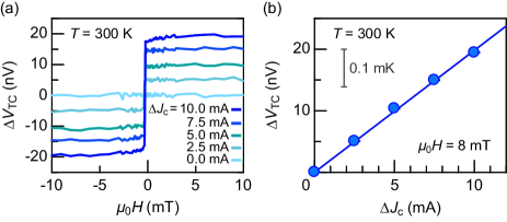
We first checked the appearance of the conventional SPE signals in the present Pt/BiGa:LuIG sample at the temperature of and a low- range, . Figure 2(a) shows the dependences of for several values. With the application of , clear signals appear and the sign of changes when the direction is reversed. Figure 2(b) shows the -amplitude dependence of at . The intensity is proportional to . These results confirm that is generated by the SPE; the former result is attributed to the change of the SPE-induced heat-current direction with respect to the relative orientation between the spin accumulation of Pt and magnetization of BiGa:LuIG [see Eq. (2)], while the latter result is due to the fact that , the driving force of the SPE, scales with [see Eq. (1)].
We then applied a relatively high magnetic field to the sample, , and measured the dependence of with the intervals of . Figure 3(b) displays the measured . We observed a fine asymmetric peak structure at on top of the flat background signal. A magnified view of the - curve for is shown in Fig. 3(c), where the anomaly is marked by a blue triangle. The peak height is as small as , corresponding to the temperature change of , but the structure is fully reproducible. We confirmed that the peak disappears when [Fig. 3(c)] and also when the is applied perpendicular to the film plane [, see Fig. 3(d)], consistent with the characteristics of the SPE [Eq. (2)]. Besides, the peak amplitude was found to scale with [see Fig. 3(e)]. These results suggest that the anomaly is intrinsic and stems from the SPE.
Importantly, the peak appears for the field at which the magnon dispersion curve of BiGa:LuIG touches the TA-phonon dispersion curve, as with the magnon-polaron anomaly observed in the SSE measurement Ramos2019NatCommun . For BiGa:LuIG, the acoustic magnon dispersion reads comment_on_magnon_dispersion , where is the gyromagnetic ratio, the Dirac constant, the spin of Fe3+ (), () the nearest-neighbor distance (inter-sublattice exchange constant) between Fe a- and d-sites, and , , and the constants determined by the occupation ratio of Fe3+ in the octahedral and tetrahedral sites of BiGa:LuIG Ramos2019NatCommun . On the other hand, the phonon dispersions read , where the is the phonon sound velocity for the transverse-acoustic (TA) [longitudinal-acoustic (LA)] mode and determined as () Ramos2019NatCommun . At a low , the magnon branch intersects the TA-phonon branch twice [see Fig. 3(a)]. By increasing , the magnon branch shifts toward high frequencies due to the Zeeman interaction (), while the phonon branch remains unchanged. When becomes , the TA-phonon branch becomes tangential to the magnon dispersion [see Fig. 3(a)]. For the branches are apart from each other. At the touching condition , the largest overlap region between the magnon and phonon dispersion curves leads to the maximal magnon-polaron formation Kikkawa2016PRL ; Flebus2017PRB . Furthermore, the observed peak shape is close to that observed in the SSE measurement Ramos2019NatCommun . These suggest that the observed peak is attributed to the magnon-polaron-induced SPE enhancement. The peak intensity relative to the background signal is , in reasonable agreement with that observed in the SSE ( Ramos2019NatCommun ).
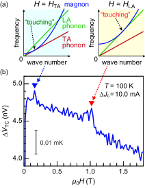
We carried out systematic dependence measurements. Figure 4(a) shows the measured for the various sample temperatures of with . At all the values, clear SPE signals were observed. In Fig. 4(b), we plot the dependences of (blue plots) and the corresponding values (gray plots) at . When is decreased from , the SPE-induced takes a broad maximum around and it monotonically decreases by further decreasing . The dependence is qualitatively consistent with the previous results on the SSE in Pt/YIG films Kikkawa2015PRB ; Jin2015PRB ; Guo2016PRX ; comment_on_T-dep_0 . Importantly, as marked by the blue triangles in Fig. 4(a), magnon-polaron-induced peaks are also visible on top of the smooth background at specific field values . The peak field shifts toward lower values by decreasing [see Figs. 4(a) and 4(d)]. This behavior is consistent with the magnon-polaron SSE in Pt/BiGa:LuIG films Ramos2019NatCommun (see Sec. B of SM, where the previous magnon-polaron SSE peak fields are shown as a function of SM ) and attributable to the dependence of the stiffness parameter () of the magnon dispersion Ramos2019NatCommun . Besides, the magnon-polaron peak amplitude , or , tends to decrease with decreasing [Fig. 4(c)], in agreement with the SSE results in Pt/BiGa:LuIG films in the same range Ramos2019NatCommun ; comment_on_T-dep_1 (see Sec. B of SM, where the details on the determination of peak intensity and field are described SM ).
We found the magnon-polaron peak structure appears also when the magnon branch tangentially touches the LA-phonon dispersion. Figure 5(b) shows the dependence of at for and magnon-LA-phonon-touching . Interestingly, in addition to the peak at , a similar peak structure manifests at on top of the background signal, as marked by the blue and red triangles, respectively. Here, the overall negative slope in the background is due to the reduction of SPE by the field-induced freeze-out of the magnons Itoh2017PRB ; Kikkawa2015PRB ; Jin2015PRB ; Guo2016PRX . The peak-field value is again in reasonable agreement with those we have measured for the magnon-polaron SSE in Pt/BiGa:LuIG at the magnonLA-phonon touching field [Fig. 5(a)] Ramos2019NatCommun , indicating that the peak at is originated from the magnon polarons induced by the coupling between magnons and LA-phonons in BiGa:LuIG. The result further corroborates that the SPE is enhanced by the magnon-polaron formation.
The appearance of the peaks in the SPE can be understood in terms of the enhanced lifetime of spin current by the magnon-phonon hybridization in a similar way as the SSE Kikkawa2016PRL ; Flebus2017PRB ; Ramos2019NatCommun . Assuming that the phonon lifetime is longer than the magnon one, the spin current carried by the hybridized modes exhibits a longer lifetime than pure magnonic spin currents Kikkawa2016PRL ; Flebus2017PRB . Hence, in the presence of the hybridization, the amount of spin current in BiGa:LuIG that reaches the interface and interacts with electrons of Pt can be increased, which reinforces the SPE. The effect is maximized when the magnetic field is tuned to the touching condition , since the magnons and phonons can be hybridized over the largest volume in -space Flebus2017PRB ), which shows up as the peak structures in the SPE signal at .
IV IV. CONCLUSION
To summarize, we observed anomalous peaks in -dependent SPE signals in a Pt/BiGa:LuIG system. The anomalies appear at the onset values for hybridized magnon-phonon excitations (magnon-polaron formation), at which the magnon and phonon branches in BiGa:LuIG touch with each other. The observed peaks can be interpreted as the enhanced spin current caused by its lifetime increase due to the hybridization between magnons and long-lived phonons in BiGa:LuIG, which leads to the increased heat-current generation in the SPE. Future works should address the experimental validity of the Onsager reciprocity Flebus2017PRB ; Ohnuma2017PRB ; Sola2019SciRep for the magnon-polaron peaks between the SPE and SSE. Furthermore, exploring the continuous BiGa:LuIG thickness dependence of the SPE via thermography Daimon2019 may be interesting to determine the length scales for magnon-polaron formation (magnon-phonon conversion) Rameshti2019PRB and propagation Flebus2017PRB from the interface.
ACKNOWLEDGMENTS
We thank K. Uchida, R. Iguchi, H. Arisawa, and Y. Hashimoto for valuable discussions. This work is a part of the research program of ERATO “Spin Quantum Rectification Project” (No. JPMJER1402) from JST, the Grant-in-Aid for Scientific Research on Innovative Area “Nano Spin Conversion Science” (No. JP26103005), Grant-in-Aid for Scientific Research (S) (No. JP19H05600), and Grant-in-Aid for Research Activity Start-up (Nos. JP19K21031 and JP19K21035) from JSPS KAKENHI, JSPS Core-to-Core program “International Research Center for New-Concept Spintronics Devices”, World Premier International Research Center Initiative (WPI) from MEXT, Japan. K.O. and T.H. acknowledge support from GP-Spin at Tohoku University.
References
- (1) A. I. Akhiezer, V. G. Bar’yakhtar, and S. V. Peletminskii, Coupled magnetoelastic waves in ferromagnetic media and ferroacoustic resonance, J. Exptl. Theoret. Phys. (U.S.S.R.) 35, 228 (1958)., Sov. Phys. JETP 8, 157 (1959).
- (2) C. Kittel, Interaction of spin waves and ultrasonic waves in ferromagnetic crystals, Phys. Rev. 110, 836 (1958).
- (3) M. I. Kaganov and V. M. Tsukernik, Phenomenological theory of kinetic processes in ferromagnetic dielectrics. II. Interaction of spin waves with phonons, J. Exptl. Theoret. Phys. (U.S.S.R.) 36, 224 (1959)., Sov. Phys. JETP 9, 151 (1959).
- (4) L. Dreher, M. Weiler, M. Pernpeintner, H. Huebl, R. Gross, M. S. Brandt, and S. T. B. Goennenwein, Surface acoustic wave driven ferromagnetic resonance in nickel thin films: Theory and experiment, Phys. Rev. B 86, 134415 (2012).
- (5) A. Rückriegel, P. Kopietz, D. A. Bozhko, A. A. Serga, and B. Hillebrands, Magnetoelastic modes and lifetime of magnons in thin yttrium iron garnet films, Phys. Rev. B 89, 184413 (2014).
- (6) A. Kamra, H. Keshtgar, P. Yan, and G. E. W. Bauer, Coherent elastic excitation of spin waves, Phys. Rev. B 91, 104409 (2015).
- (7) N. Ogawa, W. Koshibae, A. J. Beekman, N. Nagaosa, M. Kubota, M. Kawasaki, and Y. Tokura, Photodrive of magnetic bubbles via magnetoelastic waves, Proc. Natl. Acad. Sci. U.S.A. 112, 8977 (2015).
- (8) K. Shen and G. E. W. Bauer, Laser-Induced Spatiotemporal Dynamics of Magnetic Films, Phys. Rev. Lett. 115, 197201 (2015).
- (9) R. Takahashi and N. Nagaosa, Berry Curvature in Magnon-Phonon Hybrid Systems, Phys. Rev. Lett. 117, 217205 (2016).
- (10) T. Kikkawa, K. Shen, B. Flebus, R. A. Duine, K. Uchida, Z. Qiu, G. E. W. Bauer, and E. Saitoh, Magnon Polarons in the Spin Seebeck Effect, Phys. Rev. Lett. 117, 207203 (2016).
- (11) B. Flebus, K. Shen, T. Kikkawa, K. Uchida, Z. Qiu, E. Saitoh, R. A. Duine, and G. E. W. Bauer, Magnon-polaron transport in magnetic insulators, Phys. Rev. B 95, 144420 (2017).
- (12) L. J. Cornelissen, K. Oyanagi, T. Kikkawa, Z. Qiu, T. Kuschel, G. E. W. Bauer, B. J. van Wees, and E. Saitoh, Nonlocal magnon-polaron transport in yttrium iron garnet, Phys. Rev. B 96, 104441 (2017).
- (13) P. Graczyk, J. Kłos, and M. Krawczyk, Broadband magnetoelastic coupling in magnonic-phononic crystals for high-frequency nanoscale spin-wave generation, Phys. Rev. B 95, 104425 (2017).
- (14) D. A. Bozhko, P. Clausen, G. A. Melkov, V. S. L’vov, A. Pomyalov, V. I. Vasyuchka, A. V. Chumak, B. Hillebrands, and A. A. Serga, Bottleneck Accumulation of Hybrid Magnetoelastic Bosons, Phys. Rev. Lett. 118, 237201 (2017).
- (15) Y. Hashimoto, S. Daimon, R. Iguchi, Y. Oikawa, K. Shen, K. Sato, D. Bossini, Y. Tabuchi, T. Satoh, B. Hillebrands, G. E. W. Bauer, T. H. Johansen, A. Kirilyuk, Th. Rasing, and E. Saitoh, All-optical observation and reconstruction of spin wave dispersion, Nat. Commun. 8, 15859 (2017).
- (16) H. Man, Z. Shi, G. Xu, Y. Xu, X. Chen, S. Sullivan, J. Zhou, K. Xia, J. Shi, and P. Dai, Direct observation of magnon-phonon coupling in yttrium iron garnet, Phys. Rev. B 96, 100406(R) (2017).
- (17) H. Wang, D. Hou, T. Kikkawa, R. Ramos, K. Shen, Z. Qiu, Y. Chen, M. Umeda, Y. Shiomi, X. Jin, and E. Saitoh, The bimodal distribution spin Seebeck effect enhancement in epitaxial Ni0.65Zn0.35Al0.8Fe1.2O4 thin film, Appl. Phys. Lett. 112, 142406 (2018).
- (18) J. Holanda, D. S. Maior, A. Azevedo, and S. M. Rezende, Detecting the phonon spin in magnon-phonon conversion experiments, Nat. Phys. 14, 500 (2018).
- (19) S. Streib, H. Keshtgar, and G. E. W. Bauer, Damping of Magnetization Dynamics by Phonon Pumping, Phys. Rev. Lett. 121, 027202 (2018).
- (20) H. Hayashi and K. Ando, Spin Pumping Driven by Magnon Polarons, Phys. Rev. Lett. 121, 237202 (2018).
- (21) R. Schmidt, F. Wilken, T. S. Nunner, and P. W. Brouwer, Boltzmann approach to the longitudinal spin Seebeck effect, Phys. Rev. B 98, 134421 (2018).
- (22) J. Shan, A. V. Singh, L. Liang, L. J. Cornelissen, Z. Galazka, A. Gupta, B. J. van Wees, and T. Kuschel, Enhanced magnon spin transport in NiFe2O4 thin films on a lattice-matched substrate, Appl. Phys. Lett. 113, 162403 (2018).
- (23) K. Shen, Temperature-switched anomaly in the spin Seebeck effect in Gd3Fe5O12, Phys. Rev. B 99, 024417 (2019).
- (24) B. Z. Rameshti and R. A. Duine, Length scale for magnon-polaron formation from nonlocal spin transport, Phys. Rev. B 99, 060402(R) (2019).
- (25) H. T. Simensen, R. E. Troncoso, A. Kamra, and A. Brataas, Magnon-polarons in cubic collinear antiferromagnets, Phys. Rev. B 99, 064421 (2019).
- (26) E. Thingstad, A. Kamra, A. Brataas, and A. Sudbø, Chiral Phonon Transport Induced by Topological Magnons, Phys. Rev. Lett. 122, 107201 (2019).
- (27) S. Streib, N. Vidal-Silva, K. Shen, and G. E. W. Bauer, Magnon-phonon interactions in magnetic insulators, Phys. Rev. B 99, 184442 (2019).
- (28) P. Sivarajah, A. Steinbacher, B. Dastrup, J. Lu, M. Xiang, W. Ren, S. Kamba, S. Cao, and K. A. Nelson, THz-frequency magnon-phonon-polaritons in the collective strong-coupling regime, J. Appl. Phys. 125, 213103 (2019).
- (29) R. Ramos, T. Hioki, Y. Hashimoto, T. Kikkawa, P. Frey, A. J. E. Kreil, V. I. Vasyuchka, A. A. Serga, B. Hillebrands, and E. Saitoh, Room temperature and low-field resonant enhancement of spin Seebeck effect in partially compensated magnets, Nat. Commun. 10, 5162 (2019)., including Supplemental Material.
- (30) K. An, A. N. Litvinenko, A. A. Fuad, V. V. Naletov, L. Vila, U. Ebels, G. de Loubens, H. Hurdequint, N. Beaulieu, J. Ben Youssef, N. Vukadinovic, G. E. W. Bauer, A. N. Slavin, V. S. Tiberkevich, and O. Klein, Long range coupling of magnetic bi-layers by coherent phonons, arXiv:1905.12523 (2019).
- (31) K. Uchida, H. Adachi, T. Kikkawa, A. Kirihara, M. Ishida, S. Yorozu, S. Maekawa, and E. Saitoh, Thermoelectric generation based on spin Seebeck effects, Proc. IEEE 104, 1946 (2016)., ibid. 104, 1499 (2016).
- (32) A Hoffmann, Spin Hall Effects in Metals, IEEE Trans. Magn. 49, 5172 (2013).
- (33) J. Sinova, S. O. Valenzuela, J. Wunderlich, C. H. Back, and T. Jungwirth, Spin Hall effects, Rev. Mod. Phys. 87, 1213 (2015).
- (34) J. Flipse, F. K. Dejene, D. Wagenaar, G. E. W. Bauer, J. Ben Youssef, and B. J. van Wees, Observation of the Spin Peltier Effect for Magnetic Insulators, Phys. Rev. Lett. 113, 027601 (2014).
- (35) V. Basso, E. Ferraro, A. Magni, A. Sola, M. Kuepferling, and M. Pasquale, Nonequilibrium thermodynamics of the spin Seebeck and spin Peltier effects, Phys. Rev. B 93, 184421 (2016).
- (36) S. Daimon, R. Iguchi, T. Hioki, E. Saitoh, and K. Uchida, Thermal imaging of spin Peltier effect, Nat. Commun. 7, 13754 (2016).
- (37) S. Daimon, K. Uchida, R. Iguchi, T. Hioki, and E. Saitoh, Thermographic measurements of the spin Peltier effect in metal/yttrium-iron-garnet junction systems, Phys. Rev. B 96, 024424 (2017).
- (38) R. Itoh, R. Iguchi, S. Daimon, K. Oyanagi, K. Uchida, and E. Saitoh, Magnetic-field-induced decrease of the spin Peltier effect in Pt/Y3Fe5O12 system at room temperature, Phys. Rev. B 96, 184422 (2017).
- (39) K. Uchida, R. Iguchi, S. Daimon, R. Ramos, A. Anadón, I. Lucas, P. A. Algarabel, L. Morellón, M. H. Aguirre, M. R. Ibarra, and E. Saitoh, Enhancement of the spin Peltier effect in multilayers, Phys. Rev. B 95, 184437 (2017).
- (40) Y. Ohnuma, M. Matsuo, and S. Maekawa, Theory of the spin Peltier effect, Phys. Rev. B 96, 134412 (2017).
- (41) T. Seki, R. Iguchi, K. Uchida, and K. Takanashi, Visualization of anomalous Ettingshausen effect in a ferromagnetic film: Direct evidence of different symmetry from spin Peltier effect, Appl. Phys. Lett. 112, 152403 (2018).
- (42) A. Yagmur, R. Iguchi, S. Geprägs, A. Erb, S. Daimon, E. Saitoh, R. Gross, and K. Uchida, Lock-in thermography measurements of the spin Peltier effect in a compensated ferrimagnet and its comparison to the spin Seebeck effect, J. Phys. D 51, 194002 (2018).
- (43) A. Sola, V. Basso, M. Kuepferling, C. Dubs, and M. Pasquale, Experimental proof of the reciprocal relation between spin Peltier and spin Seebeck effects in a bulk YIG/Pt bilayer, Sci. Rep. 9, 2047 (2019).
- (44) S. Daimon, K. Uchida, N. Ujiie, Y. Hattori, R. Tsuboi, and E. Saitoh, Thickness dependence of spin Peltier effect visualized by thermal imaging technique, arXiv:1906.01560 (2019).
- (45) T. Kikkawa, M. Suzuki, J. Okabayashi, K. Uchida, D. Kikuchi, Z. Qiu, and E. Saitoh, Detection of induced paramagnetic moments in Pt on Y3Fe5O12 via x-ray magnetic circular dichroism, Phys. Rev. B 95, 214416 (2017).
- (46) The -dependent data (for each temperature and charge current ) shown in the main text are obtained by averaging -times repeated measurements. Here, at each magnetic field value for one measurement, the TC voltage was accumulated by repeating the process of the -polarity change of . Hence, the total data accumulation number for each point is from to .
- (47) See Supplemental Material (SM) for details on experimental methods and data analysis.
- (48) The magnon dispersion is derived in SM for Ref. Ramos2019NatCommun , which is based on a two-sublattice ferrimagnetic model and well reproduces the dispersion for a BiGa:LuIG film experimentally determined via Brillouin light scattering spectroscopy. A similar theoretical expression is obtained in Ref. Sparks-text .
- (49) M. Sparks, Ferromagnetic-Relaxation Theory, (McGraw-Hill, New York, 1964), pp. 5660.
- (50) T. Kikkawa, K. Uchida, S. Daimon, Z. Qiu, Y. Shiomi, and E. Saitoh, Critical suppression of spin Seebeck effect by magnetic fields, Phys. Rev. B 92, 064413 (2015).
- (51) H. Jin, S. R. Boona, Z. Yang, R. C. Myers, and J. P. Heremans, Effect of the magnon dispersion on the longitudinal spin Seebeck effect in yttrium iron garnets, Phys. Rev. B 92, 054436 (2015).
- (52) E.-J. Guo, J. Cramer, A. Kehlberger, C. A. Ferguson, D. A. MacLaren, G. Jakob, and M. Kläui, Influence of Thickness and Interface on the Low-Temperature Enhancement of the Spin Seebeck Effect in YIG Films, Phys. Rev. X 6, 031012 (2016).
- (53) We note that the dependence of measured originates from not only the intrinsic -dependent SPE but also various -dependent factors, such as the thermal conductivity and heat capacity of the GE-varnish and interfacial thermal resistance between the thermocouple, GE-varnish, and sample, which should be considered for further quantitative discussions.
- (54) Although the origin of the observed dependence of [Fig. 4(c)] remains to be clarified, it may be explained by the dependence of the lifetime difference between magnons and phonons; the magnon lifetime of BiGa:LuIG may be reduced at higher temperatures due to strong magnon-magnon scatterings (magnetic fluctuation), since the magnetic ordering temperature of BiGa:LuIG is close to room temperature . Therefore, the effect of magnon-polaron formation on the SPE signal can become more (less) prominent at the higher (lower) ranges, which may be responsible for the observed dependence of [Fig. 4(c)].
- (55) According to our previous SSE study Ramos2019NatCommun , the peak intensity induced by magnonLA-phonon hybridization increases with decreasing , so that we carried out the experiment at to well resolve the magnon-polaron features in the SPE.