Molybdenum dichalcogenide cathodes for aluminium-ion batteries
Abstract
Many successful battery electrodes are based on 2D-layered materials. We have studied aluminium-ion batteries using molybdenum dichalcogenides: \ceMoS2, \ceMoSe2 and MoSSe as active cathode materials. The batteries showed clear discharge voltage plateaus in the ranges 1.6 - 1.4 V for \ceMoS2 and \ceMoSe2, and 0.6 - 0.5 V for MoSSe. \ceMoS2 and \ceMoSe2 have similar crystal structures, interestingly we found that \ceMoSe2 performed better than \ceMoS2. MoSSe exhibited a higher specific capacity over \ceMoS2 and \ceMoSe2, but the energy density was lower than \ceMoSe2 at a current rate of 40 mA g-1. \ceMoSe2 cells recorded a discharge capacity of 110 mAh g-1 with an average potential in the range of 2.0 - 1.8 V and 1.5 - 0.8 V during discharge. The cells were stable at 100 mA g-1 for over 200 cycles with 90% coulombic efficiency.
Keywords Aluminium-ion battery Layered compounds Molybdenum dichalcogenides Cathode Electrochemistry
1 Introduction
Aluminium-ion batteries (AIBs) offer an alternative to the prevalent lithium-ion battery (LIB) technology. Aluminium being the most abundant metal in the Earth’s crust, these batteries will not only be much cheaper, but hold promise to solve other problems such as recycleability and thermal runaway. Furthermore, the multivalent nature of aluminium may result in a higher specific capacity and energy density compared with other monovalent battery types. Research on AIBs is still in its early stages and current work focuses mainly on electrolytes and cathode materials. In this article, we explore different molybdenum dichalcogenide-based materials and their mechanism of energy storage. We expected that two-dimensional (2D) layered materials that support intercalation of charged species might be suitable as active cathode materials in AIBs [22, 23].
The most common AIB electrolyte is currently the ionic liquid 1-ethyl-3-methylimidazolium/tetrachloroaluminate (\ce[EMIm]+/\ceAlCl4-), although many other alternatives are under investigation [1]. The most studied cathode types are graphite-based, where chloroaluminate ions \ceAlCl4- have been shown to intercalate/deintercalate during the charging/discharging processes. Various forms of graphite such as fluorinated graphite [2], Kish graphite flakes [3], three-dimensional graphitic foam [4], few-layer graphene aerogels [5], and several others have been tested. Analytical techniques such as X-ray diffraction (XRD), Raman spectroscopy and X-ray photoelectron spectroscopy (XPS) have been used broadly to verify the intercalation/deintercalation mechanism.
Molybdenum dichalcogenides (\ceMoX2 where X=S, Se or Te) display similar properties as graphite. They have a 2D-layered structure, which allows intercalation of ions and are electrically conductive. Lower volumetric expansion on cycling is an advantage these materials have over graphitic cathodes [6, 7]. Amongst various transition metal chalcogenides, \ceMoS2 has been extensively studied as a cathode for rechargeable batteries [8, 9, 21, 20], making them attractive candidates for AIB cathodes. In 2015, Geng et al. found that \ceAl^3+ ions fully intercalated into chevrel phase \ceMo6S8 with the cations occupying two different sites in the crystal lattice [10]. This mechanism was called the ’rocking chair’ mechanism where charge carrying species shuttled back and forth between intercalating electrodes during cycles while the overall electrolyte concentration remains constant. The discharging and charging reactions at the anode (equation 1) and cathode (equation 2) were proposed as follows:
| (1) | ||||
Three years later, Li et al. prepared \ceMoS2 microspheres by a simple hydrothermal method [11]. They proposed a similar mechanism where \ceAl^3+ ions inserted into the electrode accompanied by a phase transformation at the electrode interface. Li and his group confirmed this phase-transition by using ex-situ XPS and XRD etching techniques. The reaction equations for this battery system at the cathode (equation 3) and anode (equation 4) were proposed as follows:
| (2) | ||||
In general, these cells showed low energy density and had reversibility issues in the redox processes. It has been reported that transition metal dichalcogenide electrodes tend to transition from a 2H phase into a more conducting 1T phase when used in a battery [12]. A hybrid \ceMg^2+/\ceLi+ cell was tested using bulk \ceMoS2 as a cathode material. During cyclic voltammetry (CV) scans, the authors associated the first cathodic peak, with a phase transition. 2H phase \ceMoS2 was converted to 1T phase during initial ion intercalation. This seems to be a common phenomenon for molybdenum dichalcogenides, since Li et al. observed similar transitions in sodium ion batteries [13, 19]. It mostly takes place during the first cycle and since the phase change is irreversible, it can be detected in a cyclic voltammogram.
In this work, we studied a range of 2D molybdenum dichalcogenides including \ceMoS2, \ceMoSe2 and \ceMoSSe, and tested them as cathodes for non-aqueous AIBs. Our unpublished, preliminary density functional theory (DFT) calculations indicated a significant decrease in inter-layer spacing of these materials when \ceAl^3+ cations were assumed to intercalate (owing to the very high charge density of \ceAl^3+). Therefore, we propose intercalation of structurally distorted \ceAlCl4- anions into the cathode layers. Surprisingly we found that \ceMoSe2-based cathodes performed different and better than all of the other molybdenum dichalcogenides.
2 Results and Discussion
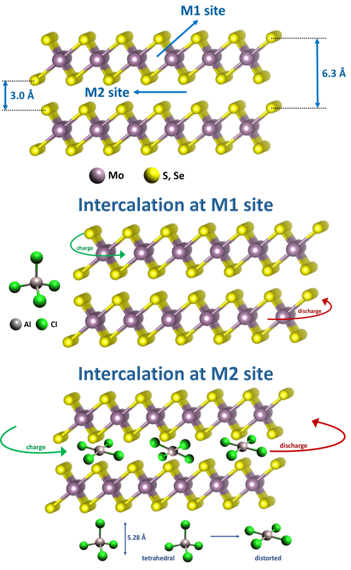
Figure 1 shows the crystal structure of \ceMoX2 where X is sulfur (S) and/or selenium (Se). The material has two vacant sites for intercalation — M1 and M2. M1 denotes the spaces in between the X-Mo-X atoms, whereas M2 represents the space created between the \ceMoX2 layers as shown in Figure 1 a). The inter-layer distance in \ceMoX2 is 6.3 Å with a gallery height of 3 Å. The layers are held together by weak van der Waals (vdW) forces. M2 presents an open network and provides various interstitial sites for intercalation. Since \ceAlCl4- ions are 5.28 Å in diameter, as reported by Takahashi et al. [14], they undergo some distortion during intercalation to fit into these layers. Our preliminary results showed that \ceAl^3+ would ‘contract’ the \ceMoX2 layers when trying to intercalate, making \ceAlCl4- anion intercalation more likely. Also, the triply charged \ceAl^3+ cation has to overcome strong electrostatic forces from the \ceS^2- or \ceSe^2- anion network in order to enter, making the intercalation process slow and most likely not reversible. Therefore, we propose intercalation of \ceAlCl4- anions from the electrolyte into M2 sites of \ceMoX2 during charge. Galvanostatic cycles, cyclic voltammetry (CV), X-Ray diffraction (XRD), Raman spectra and X-Ray Photoelectron Spectroscopy (XPS) results discussed later, strongly support our claim of a reversible intercalation process especially in \ceMoSe2.
A modified two-electrode polyether ether ketone (PEEK) cell (Figure 2) was used for conducting preliminary electrochemical tests. Cathode preparation, electrolyte synthesis, and cell configuration are described in the Experimental Methods section.
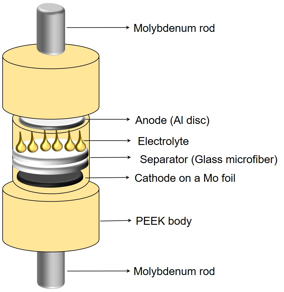
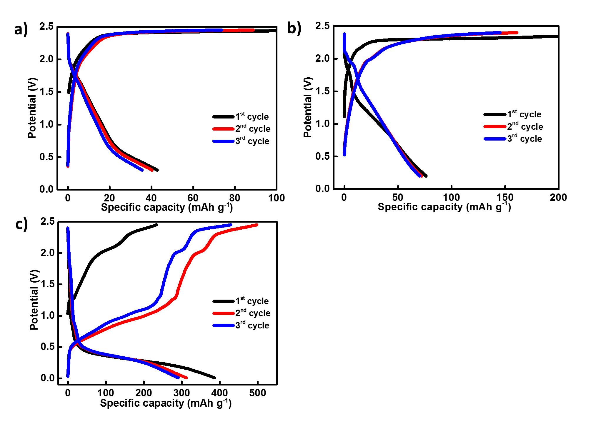
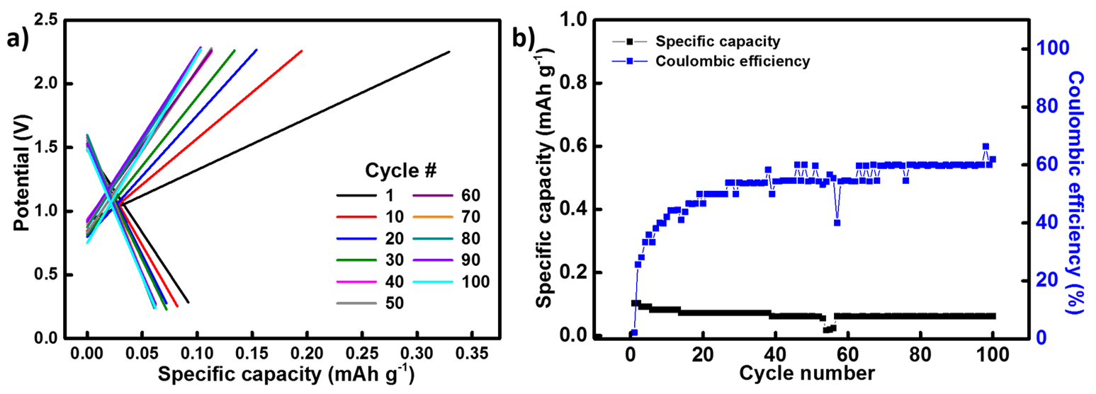
Figure 3 a)–c) shows the charge/discharge cycles (CDCs) for \ceMoS2, \ceMoSe2 and MoSSe at a current rate of 40 mA g-1. The discharge capacity of \ceMoS2 in its first cycle was found at 45 mAh g-1, Figure 3 a). Comparing this with its first CV scan (Figure 3 a inset), a good correlation between the discharge voltage plateau and reduction peaks, and other redox features was found. The voltage bend during discharge at 2.0 V matched well with the reduction peak at 2.0 V. The other reduction peak at 1.0 V, however did not correspond to any of the other peaks. With discharge voltage bends between 2.0 - 1.8 V and 1.5 -0.8 V, the first CV scan for \ceMoSe2 displayed two reduction peaks at 1.65 V (point A) and 1.0 V (point B), Figures 3 b) and 3 b inset). The peak at 1.0 V suggested an irreversible reaction since this peak was absent in the following scans. Based on this, we agree with Li et al.’s interpretation and attributed this peak to an irreversible phase transition [13]. During this transition, the semi-conducting 2H phase converted into a more metallic 1T phase. This transition seemed to increase the interlayer spacing of \ceMoSe2 by reducing the vdW forces that exist between the two layers [12]. Al/MoSSe cells showed three distinct plateaus during charge at 1.2 V, 2.0 - 2.1 V and 2.3 - 2.4 V in its first cycle, with a discharge plateau at 0.5 V shown in Figure 3 c). Capacities of all molybdenum dichalcogenides were recorded at different current rates of 25, 40 and 100 mA g-1, and displayed in Figure 3 d). Since \ceMoSe2 displayed stable specific capacities at all current rates, we recorded further 200 cycles at a high current rate of 100 mA g-1. A highly reversible electrochemical reaction was observed since the capacity remained at 35 mAh g-1 after 200 cycles (Figure 3 e)) at 100 mA g-1. The presence of multiple charging plateaus in MoSSe might correspond to various oxidation processes occurring when \ceAlCl4- interacts individually with S and Se atoms. The first CV scan in Figure 3 c inset showed an irreversible reduction potential at 0.9 V, point B’, like \ceMoSe2, implying a similar phase transition. It seems MoSSe undergoes a lattice distortion and the material loses its long range order after converting to its 1T phase. This might be the reason why the cells fail to deliver a stable capacity. In addition, a significant difference was observed charge/ discharge curves of all the molybdenum dichalcogenide cathodes– similar to what was previously reported by Li et al. in 2018 [11]. Electrochemical polarisation at the electrode interface might be responsible for the uneven potentials. Formation of an insulating layer on the cathode surface by the new Al-\ceMoX2 complexes might have attributed to the overpotential.
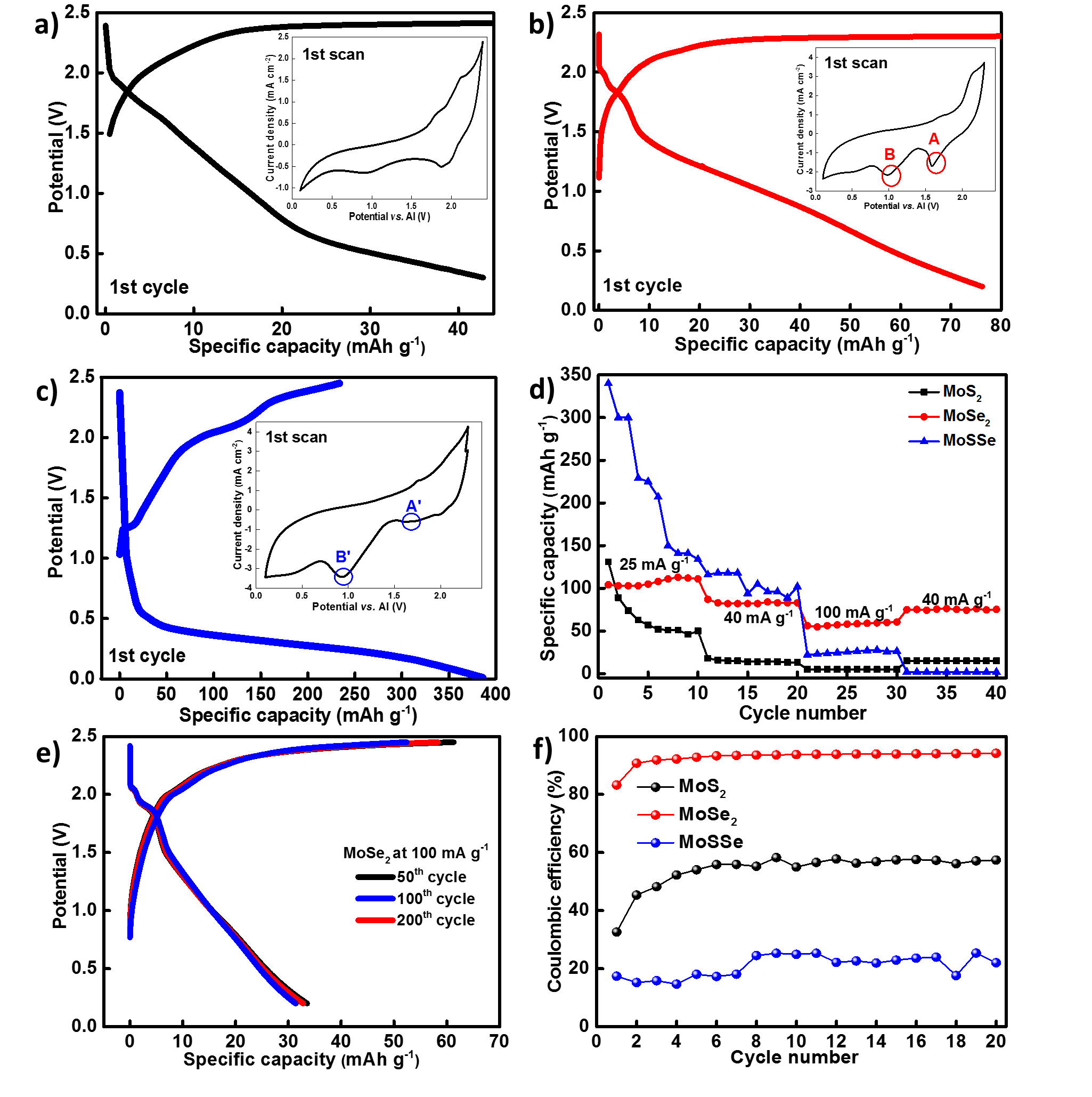
Electrochemical performance of a blank cell with an uncoated Mo foil (Figure 11) showed that the current collector did not contribute to the cell’s capacity. Both \ceMoS2 and \ceMoSe2 have similar interlayer distance (6.3 Å) and a gallery height of 3.0 Å. However, \ceMoSe2 showed a higher capacity and a more stable cycle life. To account for this behaviour, we compared the CVs of all electrodes at a scan rate of 10 mV s-1 in Figure 4. Different charge-storage mechanisms lead to distinct features in the CVs. Ideal capacitors result in a rectangular CV shape. Due to the absence of Faradaic processes, the charging/discharging currents become directly proportional to the scan speed. Batteries show oxidation and reduction peaks in their voltammograms because the charge storage takes place via reversible redox processes [15]. We observed that the CVs of \ceMoSe2 and MoSSe in Figure 4 b) and 4 c) covered a broader area suggesting an additional capacitor-like charge storage mechanism. The non-Faradaic process taking place at the surfaces of \ceMoSe2 and MoSSe might have added to their original capacity values. Also, the peak indicating phase transition from 2H1T at 0.9 - 1.0 V was visible only for \ceMoSe2 and MoSSe. Hence, it can be concluded that the charge storage in \ceMoS2 is primarily based on reversible oxidation and reduction of Mo from \ceMo^4+ to \ceMo^5+ with oxidation peaks visible at 1.8 V (O1) and 2.1 V (O2), and a corresponding reduction peak at 2.0 V (R3), Figure 4 a). Two more reduction peaks were found at 1.6 V (R2) and 0.9 V (R1). However, their peak intensities decreased with every scan. CV scans of Al/\ceMoSe2 cells in Figure 4 b) indicated a reversible electrochemical process, which was in agreement with their CDCs. The scans overlapped with each other displaying two oxidation peaks at 1.7 V (O’1) and 2.1 V (O’2) and corresponding reduction peaks at 1.8 V (R’1) and 1.6 V (R’2). In Figure 4 c) an oxidation and a reduction peak at 1.7 V (O”1) and 1.8 V (R”1) was observed for Al/MoSSe respectively. R”1’s peak intensity increased after every scan, which might suggest sluggish kinetics in the system; perhaps due to strong interaction between the positive metal ion and the intercalating anion. The voltammogram became more capacitor-like after a few scans, indicating the absence of reversible redox processes. The phenomena indicates that an initial intercalation of anions into the layers of MoSSe was followed by surface adsorption of \ceAlCl4- anions.
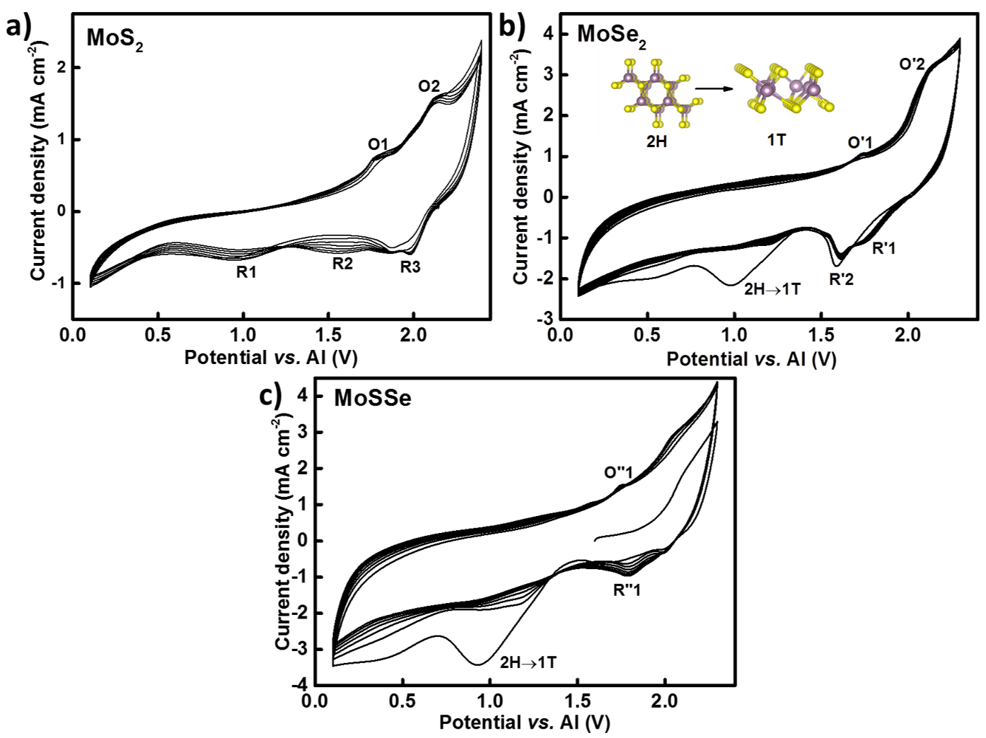
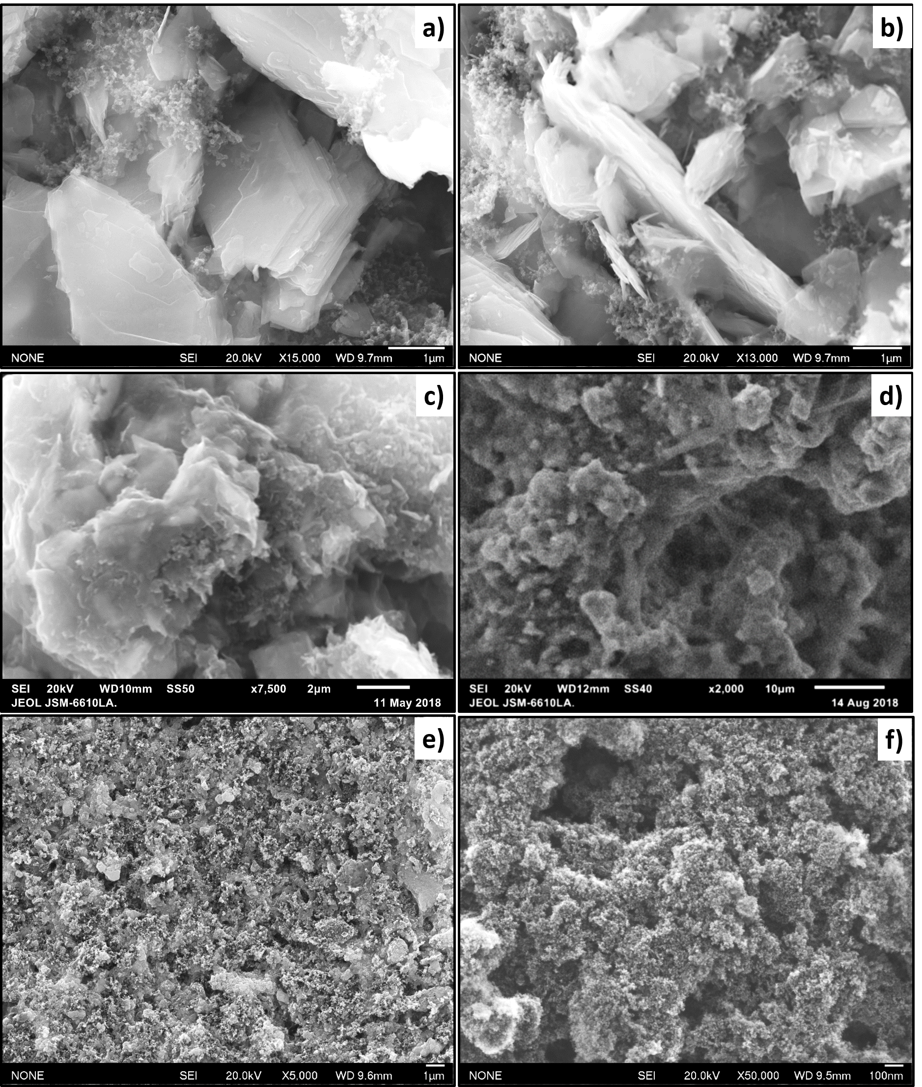
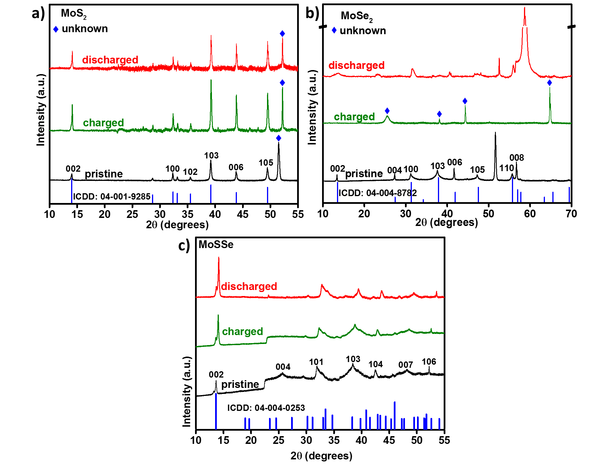
Figure 5 shows the XRD patterns of \ceMoS2, \ceMoSe2 and MoSSe electrodes. Pristine (in black), charged (in green) and discharged (in red) cathodes were compared after 30 cycles each. \ceMoS2 cells displayed a very small shift in their d-spacings. The peak at 14.21 for 002 plane (6.22 Å) shifted to 14.02 (6.32 Å), as shown in Figure 5 a). Most of the peaks retained their positions after charge and discharge showing no significant change in the lattice dimensions. A completely different XRD pattern appeared after charging for Al/\ceMoSe2 cells, as new peaks appeared at 2 values, displayed in Figure 5 b). Diffraction peaks of 002, 100, 110 and 008 planes reappeared after discharge. Every time the cells were charged, \ceMoSe2 seemed to adopt this new crystal lattice. However, the characteristic peaks of \ceMoSe2 reappeared after discharge. This follows closely the observations made by Rani et al., where they proved intercalation of ions into the layers of fluorinated natural graphite during charging using X-ray diffraction data [2]. This strongly confirms our hypothesis of a reversible intercalation taking place in \ceMoSe2. It was interesting to note that MoSSe did not have a well-defined crystal structure to begin with, Figure 5 c). The patterns after charge and discharge did not look any different from the untested cathode. This confirmed MoSSe layers did not undergo any significant expansion and the initial specific capacities at 250 mAh g-1 came from the non-Faradaic reactions via electrostatic absorption of the \ceAlCl4- anions onto the electrode’s surface. Furthermore, the material underwent irreversible changes resulting in cathode degradation after a few cycles. The images obtained from the Scanning Electron Microscope (SEM) have been shown in Figure 12. While \ceMoS2 and \ceMoSe2 displayed a layered structure in Figure 12 a) and b) respectively, MoSSe lacked a long-range order. The diffraction patterns of all the Al-Mo-Se complexes present in the ICDD database have been compared with the new complex reported in Figure 5.
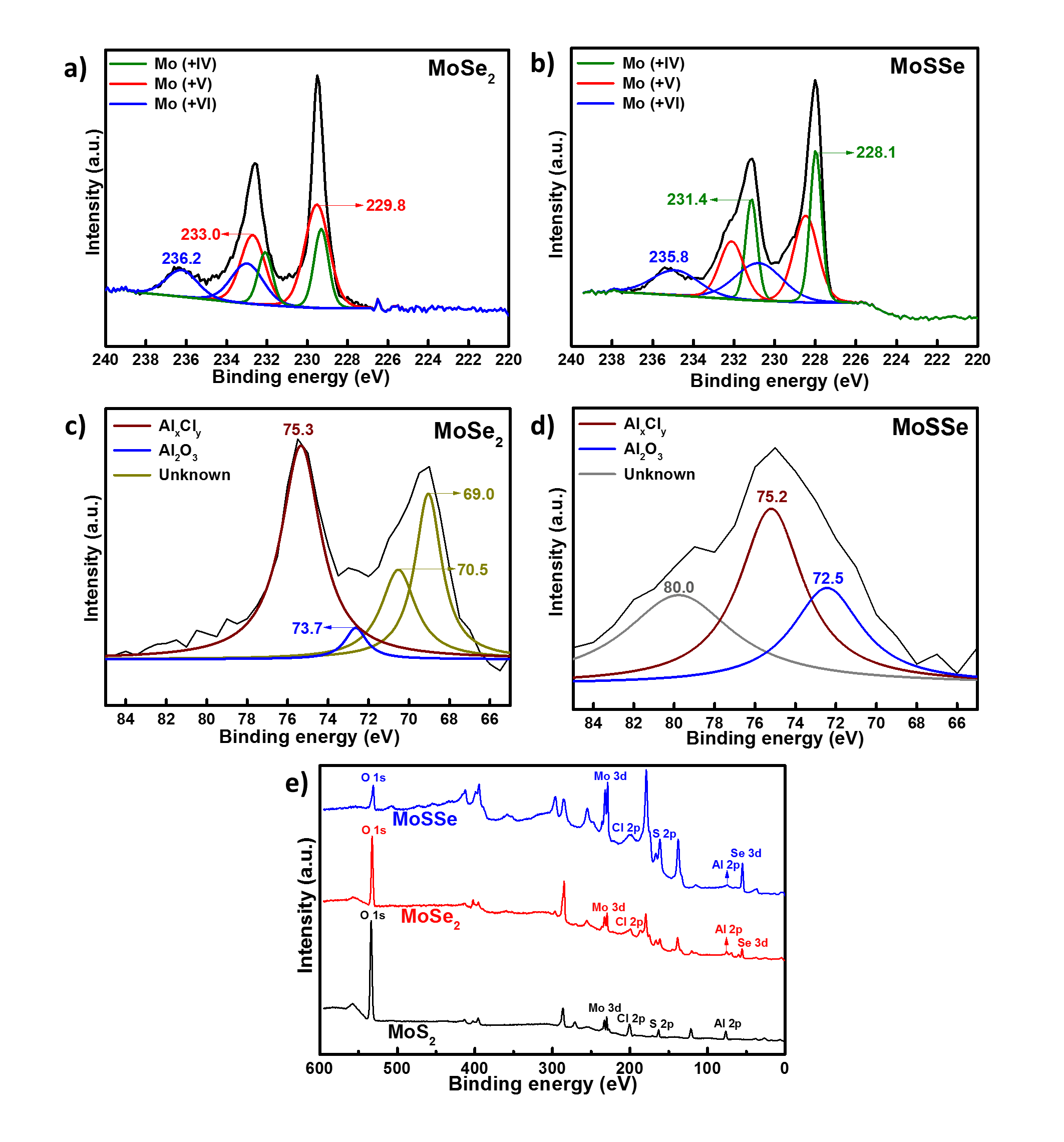
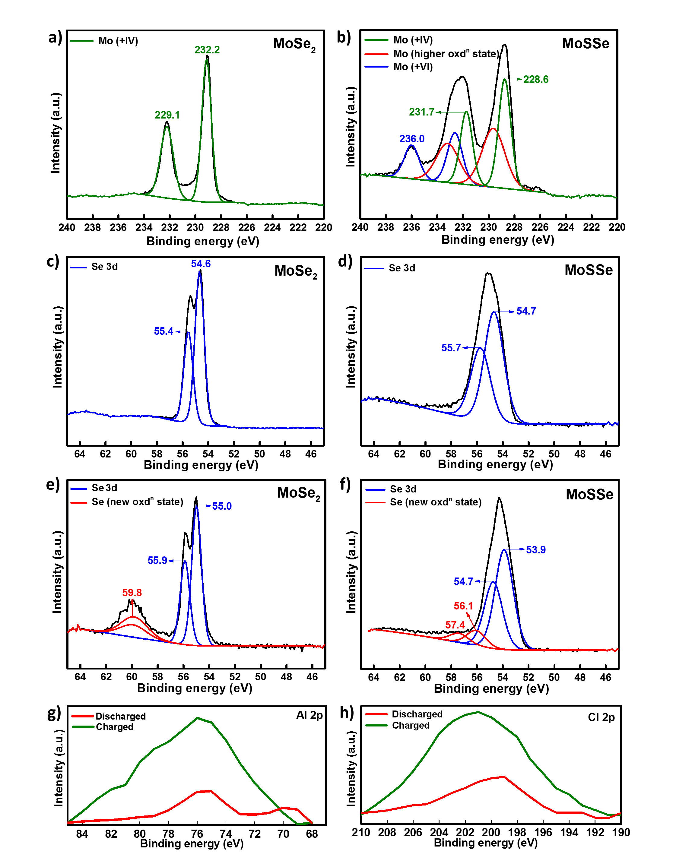
To further understand the interactions between \ceAlCl4- and \ceMoSe2 we used XPS, which is a useful method for distinguishing various oxidation states and helps in identifying different polymorphs (2H and 1T) [12]. The detailed narrow spectrum scans in Figure 6 show the binding energies of Mo (3d5/2 and 3d3/2, Figure 6 a) and b)) and Al 2p peaks for charged \ceMoSe2 (Figure 6 c)) and MoSSe electrodes (Figure 6 d)). In pristine \ceMoSe2, two peaks appeared at 229.1 eV and 232.2 eV corresponding to 3d5/2 and 3d3/2 (Figure 8 a)). Selenium displayed a doublet at 55.4 eV and 54.6 eV corresponding to Se 3d3/2 and 3d5/2 respectively (Figure 8 c)). Peak splitting in an XPS spectrum can indicate a phase change or a change in oxidation state of the said element. After charge, the peak for Mo 3d split into three doublets indicating the presence of multiple oxidation states or phases of Mo (Figure 6 a)). Se 3d deconvoluted into four peaks after charge, Figure 8 e), confirming presence of more than one phase after charge. This was similar to observations made by Fan et al. where they used \ceMoS2/graphene cathode in a hybrid \ceMg^2+/\ceLi+ cell. Pristine electrodes of MoSSe contained Mo in more than one oxidation state, and provided evidence for the presence of both 2H and 1T polymorphs, Figure 8 b). After charging, the width of peaks at 231.7 eV (Mo 3d5/2, in green) and 228.6 eV (Mo 3d3/2, in green) increased as displayed in Figure 6 b). After comparing Figure 8 d) and f), we noticed that the Se 3d spectrum deconvoluted into four peaks after charging the MoSSe cells. An increase in the peak width was observed for both Mo and Se binding energies. A new peak at 236 eV in Mo 3d spectra (in blue) for \ceMoS2, \ceMoSe2 and MoSSe electrodes was assigned to Mo6+ species typically present in molybdenum oxide, \ceMoO3.
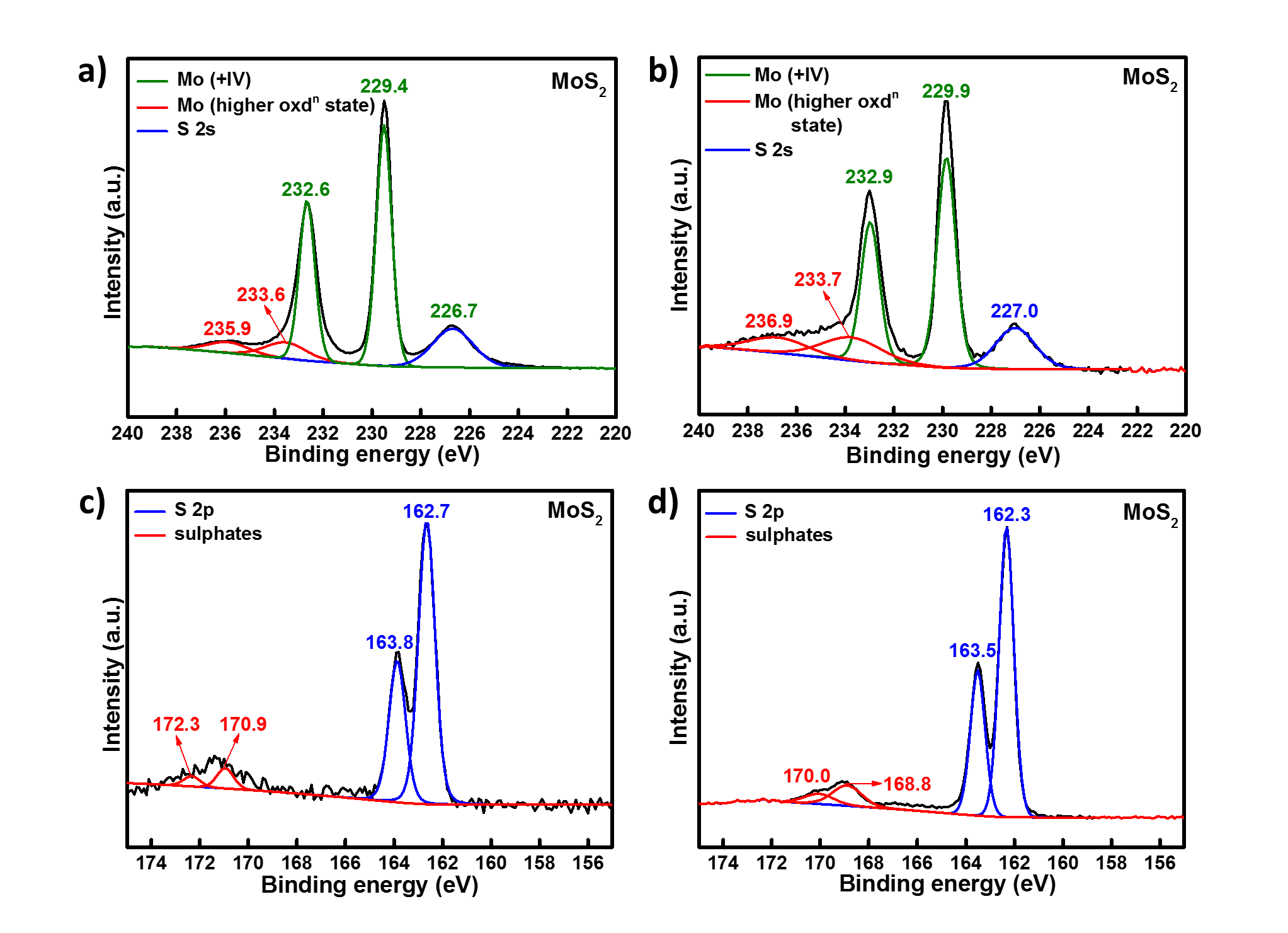
Presence of new peaks and peak shifts that were detected in Mo 3d spectra for charged \ceMoS2 and \ceMoSe2 cathodes, were not observed in MoSSe (cf. Figures 7 a), b), 6 a), and 8 a)). This further confirms the absence of redox reactions and that the capacity was mainly derived from a surface-based charge storage. As expected, a general trend was observed for all the three cathodes, where the charged electrodes showed higher concentration of aluminium and chlorine than discharged electrodes as seen in Figure 8 g) and h). The XPS spectra support the observation that \ceMoSe2 underwent a phase transformation that made it a better performing cathode than \ceMoS2. Further analysis is needed to fully understand the mechanism of MoSSe.
Charged \ceMoSe2 electrodes displayed binding energies of Al 2p at 77 eV (in red) and 76 eV (in blue) corresponding to chlorides (AlxCly) and \ceAl2O3 respectively in Figure 6 c). New peaks were observed at much lower binding energies — 69 and 70 eV (in green) suggesting the presence of a new complex with an increased electron density around aluminium. An overall spectra of charged \ceMoS2, \ceMoSe2 and MoSSe cathodes is shown in Figure 6 e) indicating the presence of Al and Cl (from chloroaluminates) and oxygen (from \ceMoO3).
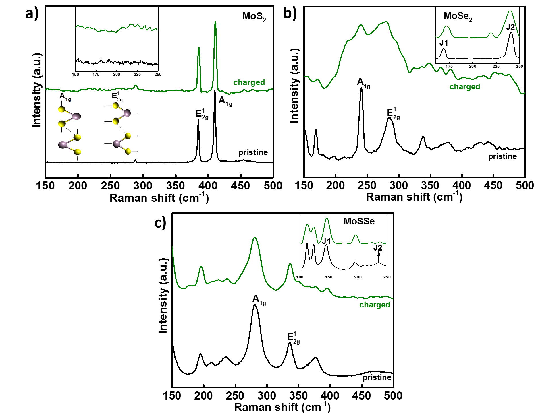
In addition, we compared the Raman spectra of pristine and charged cathodes to detect shifts in vibrational modes shown in Figure 9. Yang et al. and Sharma et al. have reported that E and A are the most intense vibrational modes for molybdenum dichalcogenides [16, 17, 18]. Peaks corresponding to E and A modes for \ceMoS2 (Figure 9 a)) are prominent at 384.6 cm-1 and 410.2 cm-1 respectively. A indicates an out-of-plane symmetric displacement of S atoms, whereas E suggests an in-layer displacement. Also, separation between the two peaks indicates a multi-layer structure, which was observed for all three materials. No significant peak shift or peak broadening was observed for the charged \ceMoS2 electrode. For 2H \ceMoSe2 (Figure 9 b)), A is the most intense vibration occurring at a frequency lower than that of E. When the number of layers decreases, the A mode softens and an increase in full-width-at-half-maximum (FWHM) is detected. Spectra generated after intercalation were different from the pristine cathodes because phase conversion from 2H to 1T decreases the molecule’s symmetry and more Raman bands get active. The presence of J1 and J2 peaks in addition to E and A at lower wavelengths suggest the existence of 1T phase especially for \ceMoSe2 and MoSSe (inset, Figure 9 b) and c)). This agrees with the CV scans and XPS results where a phase transition was observed for \ceMoSe2 and MoSSe. Raman results suggest that the symmetry and vibrational modes of \ceMoSe2’s crystal lattice changed after repeated cycles. It seems that the phase transformation occurring in the first few cycles for \ceMoSe2 changes its structure in a way that allows it to intercalate more \ceAlCl4- anions resulting in a higher capacity than \ceMoS2 despite both of them having a similar stricture. First principle studies on both materials shall confirm this hypothesis.
3 Conclusions
In this work, we studied systematically the charging/discharging mechanism of aluminium-ion batteries, using different molybdenum dichalcogenide cathodes. It was found that \ceMoSe2 showed a higher capacity and cyclic stability than \ceMoS2 and MoSSe. CV and XPS results indicated an irreversible phase transition to a more metallic 1T phase. This transition worked in favour of \ceMoSe2 and its capacity increased. XRD, XPS and Raman results supported the hypothesis that \ceAlCl4- intercalated reversibly into \ceMoSe2. An additional electro-capacitive behaviour was observed in \ceMoSe2 that added to the its overall capacity. The cells delivered a potential of 2.0 V with discharge capacity of 30 mAh g-1 with nearly 95% coulombic efficiency at a current rate of 100 mA g-1.
4 Experimental Section
4.1 Cathode preparation
A slurry was prepared by mixing MoX2 (85% by wt.), 9% binder (PVDF, MTI Corporation) and 6% Super-P conductive carbon (99+% metals basis, Alfa Aesar) in N-methyl pyrrolidone (NMP) (anhydrous, 99.5%, Sigma-Aldrich). this slurry was ‘doctor-bladed’ onto molybdenum foil (thickness 0.1 mm, MTI Corporation) and dried in a vacuum oven at 120°C for 12 hours to adhere the slurry on the conductive substrate and evaporate the solvent. The specific loading of the active materials was approx. 12 mg cm-2.
4.2 Electrolyte preparation
Anhydrous AlCl3 (Sigma-Aldrich) and EMImCl (97%, Sigma-Aldrich) were mixed in a molar ratio of 1.3:1, at room temperature. EMImCl was baked in vacuum for 24 hours at 100°C to remove residual moisture. Small aliquots of AlCl3 were added to EMImCl after every few minutes until the white fumes settled down. The ionic liquid was stirred for 2–3 hours until a clear brown liquid was obtained. Since the electrolyte was hygroscopic in nature, it was prepared in a N2-filled glove box with <0.1 ppm \ceH2O/\ceO2.
4.3 Cell assembly
Polyether ether ketone (PEEK) cells were used for preliminary electrochemical tests. Molybdenum rods were used as plungers to push in the electrodes as close to each other. Active material coated on molybdenum foil was used as the cathode and placed at bottom of the cell. Since this was a two-electrode setup, aluminium foil was used as both counter and reference electrode. We used Mo foil because nickel and steel showed reactivity towards the ionic liquid electrolyte and reduced its potential window. Glass microfibers (Grade GF/F, Whatman) were used as separators. 80 l of the electrolyte were used to wet the separator. Aluminium foil (thickness 0.1 mm, 99%, GoodFellow) was used as an anode and placed on top of the separator. The cell was then sealed and wrapped with a paraffin to avoid any further air or moisture contact after it was taken out of the glove-box.
References
- [1] Nicolò Canever, Nicolas Bertrand, and Thomas Nann. Acetamide: A low-cost alternative to alkyl imidazolium chlorides for aluminium-ion batteries. Chem. Commun., September 2018.
- [2] J. Vatsala Rani, V. Kanakaiah, Tulshiram Dadmal, M. Srinivasa Rao, and S. Bhavanarushi. Fluorinated Natural Graphite Cathode for Rechargeable Ionic Liquid Based Aluminum–Ion Battery. Journal of The Electrochemical Society, 160(10):A1781–A1784, January 2013.
- [3] Shutao Wang, Kostiantyn V. Kravchyk, Frank Krumeich, and Maksym V. Kovalenko. Kish Graphite Flakes as a Cathode Material for an Aluminum Chloride-Graphite Battery. ACS Appl Mater Interfaces, 9(34):28478–28485, August 2017.
- [4] Meng-Chang Lin, Ming Gong, Bingan Lu, Yingpeng Wu, Di-Yan Wang, Mingyun Guan, Michael Angell, Changxin Chen, Jiang Yang, Bing-Joe Hwang, and Hongjie Dai. An ultrafast rechargeable aluminium-ion battery. Nature, 520(7547):324–328, April 2015.
- [5] Jia Qiao, Haitao Zhou, Zhongsheng Liu, Hejing Wen, and Jianhong Yang. Defect-free soft carbon as cathode material for Al-ion batteries. Ionics, February 2019.
- [6] Yanliang Liang, Rujun Feng, Siqi Yang, Hua Ma, Jing Liang, and Jun Chen. Rechargeable Mg Batteries with Graphene-like MoS2 Cathode and Ultrasmall Mg Nanoparticle Anode. Adv. Mater., 23(5):640–643, 2011.
- [7] Junda Huang, Zengxi Wei, Jiaqin Liao, Wei Ni, Caiyun Wang, and Jianmin Ma. Molybdenum and tungsten chalcogenides for lithium/sodium-ion batteries: Beyond MoS2. Journal of Energy Chemistry, 33:100–124, June 2019.
- [8] Xiao-Lin Li and Ya-Dong Li. MoS2 Nanostructures: Synthesis and Electrochemical Mg2+ Intercalation. J. Phys. Chem. B, 108(37):13893–13900, September 2004.
- [9] Changbao Zhu, Xiaoke Mu, Peter A. van Aken, Joachim Maier, and Yan Yu. Fast Li Storage in MoS2-Graphene-Carbon Nanotube Nanocomposites: Advantageous Functional Integration of 0D, 1D, and 2D Nanostructures. Adv. Energy Mater., 5(4):n/a–n/a, February 2015.
- [10] Linxiao Geng, Guocheng Lv, Xuebing Xing, and Juchen Guo. Reversible Electrochemical Intercalation of Aluminum in Mo6S8. Chem. Mater., 27(14):4926–4929, July 2015.
- [11] Zhanyu Li, Bangbang Niu, Jian Liu, Jianling Li, and Feiyu Kang. Rechargeable Aluminum-Ion Battery Based on MoS2 Microsphere Cathode. ACS Appl. Mater. Interfaces, 10(11):9451–9459, March 2018.
- [12] Xin Fan, Rohit Ranganathan Gaddam, Nanjundan Ashok Kumar, and Xiu Song Zhao. A Hybrid Mg2+/Li+ Battery Based on Interlayer-Expanded MoS2/Graphene Cathode. Adv. Energy Mater., 7(19), October 2017.
- [13] Yifei Li, Yanliang Liang, Francisco C. Robles Hernandez, Hyun Deog Yoo, Qinyou An, and Yan Yao. Enhancing sodium-ion battery performance with interlayer-expanded MoS2–PEO nanocomposites. Nano Energy, 15:453–461, July 2015.
- [14] Katsunori Takahashi, Ying Wang, and Guozhong Cao. Ni-V2O5nH2O Core-Shell Nanocable Arrays for Enhanced Electrochemical Intercalation. J. Phys. Chem. B, 109(1):48–51, January 2005.
- [15] Handong Jiao, Junxiang Wang, Jiguo Tu, Haiping Lei, and Shuqiang Jiao. Aluminum-Ion Asymmetric Supercapacitor Incorporating Carbon Nanotubes and an Ionic Liquid Electrolyte: Al/AlCl3-[EMIm]Cl/CNTs. Energy Technol., 4(9):1112–1118, September 2016.
- [16] Linfei Yang, Lidong Dai, Heping Li, Haiying Hu, Kaixiang Liu, Chang Pu, Meiling Hong, and Pengfei Liu. Pressure-induced metallization in MoSe 2 under different pressure conditions. RSC Adv., 9(10):5794–5803, 2019.
- [17] Rao C. N. R and Waghmare Umesh Vasudeo. 2d Inorganic Materials Beyond Graphene. World Scientific, August 2017.
- [18] Chithra H. Sharma, Ananthu P. Surendran, Abin Varghese, and Madhu Thalakulam. Stable and scalable 1T MoS2 with low temperature-coefficient of resistance. Sci Rep, 8, August 2018.
- [19] Muharrem Acerce, Damien Voiry, and Manish Chhowalla. Metallic 1T phase MoS 2 nanosheets as supercapacitor electrode materials Nature Nanotech, 10(4):313-318, April 2015.
- [20] Shujiang Ding, Dongyang Zhang, Jun Song Chen, and Xiong Wen (David) Lou. Facile synthesis of hierarchical MoS 2 microsphere. Nanoscale, 4(1):95-98, 2012.
- [21] Yulian Dong, Yang Xu, Wei Li, Qun Fu, Minghong Wu, Eberhard Manske, Jorg Kroger, and Yong Lei. Insights into the Crystallinity of Layer-Structured Transition Metal Dichalcogenides on Potassium Ion Battery Performance: A Case Study of Molybdenum Disulfide. Small, 15(15):1900497, 2019.
- [22] Hua Zhang Ultrathin Two-Dimensional Nanomaterials ACS Nano, 9(10):9451-9469, October 2015.
- [23] M. S. Whittingham Electrical Energy Storage and Intercalation Chemistry. Science, 192(4244):1126-1127, June 1976.
- [24] Bing Li, Yuxin Shi, Kesheng Huang, Mingming Zhao, Jiaqing Qiu, Huaiguo Xue, and Huan Pang. Cobalt-Doped Nickel Phosphite for High Performance of Electrochemical Energy Storage. Small, 14(13):1703811, 2018.
- [25] Bing Li, Peng Gu, Yongcheng Feng, Guangxun Zhang, Kesheng Huang, Huaiguo Xue, and Huan Pang. Ultrathin Nickel–Cobalt Phosphate 2D Nanosheets for Electrochemical Energy Storage under Aqueous/Solid-State Electrolyte. Adv. Funct. Mater., 27(12):1605784, 2017.
- [26] Xiao Xiao, Lianli Zou, Huan Pang, and Qiang Xu. Synthesis of micro/nanoscaled metal–organic frameworks and their direct electrochemical applications. Chem. Soc. Rev, 49(1):301-331, January 2020.
- [27] Bing Li, Peng Gu, Guangxun Zhang, Yao Lu, Kesheng Huang, Huaiguo Xue, and Huan Pang. Ultrathin Nanosheet Assembled Sn0.91Co0.19S2 Nanocages with Exposed (100) Facets for High-Performance Lithium-Ion Batteries. Small, 14(5):1702184, 2018.
Supporting Information
Molybdenum dichalcogenide cathodes for aluminium-ion batteries
Shalini Divya, James H. Johnston, Thomas Nann*