Repeated Quantum Error Detection in a Surface Code
Abstract
The realization of quantum error correction is an essential ingredient for reaching the full potential of fault-tolerant universal quantum computation. Using a range of different schemes, logical qubits can be redundantly encoded in a set of physical qubits. One such scalable approach is based on the surface code. Here we experimentally implement its smallest viable instance, capable of repeatedly detecting any single error using seven superconducting qubits, four data qubits and three ancilla qubits. Using high-fidelity ancilla-based stabilizer measurements we initialize the cardinal states of the encoded logical qubit with an average logical fidelity of 96.1%. We then repeatedly check for errors using the stabilizer readout and observe that the logical quantum state is preserved with a lifetime and coherence time longer than those of any of the constituent qubits when no errors are detected. Our demonstration of error detection with its resulting enhancement of the conditioned logical qubit coherence times in a 7-qubit surface code is an important step indicating a promising route towards the realization of quantum error correction in the surface code.
Introduction
The feasibility of quantum simulations and computations with more than 50 qubits has been demonstrated in recent experiments Zhang et al. (2017); Bernien et al. (2017); Arute et al. (2019). Many near-term efforts in quantum computing are currently focused on the implementation of applications for noisy intermediate-scale quantum devices Preskill (2018). However, to harness the full potential of quantum computers, fault tolerant quantum computing must be implemented. Quantum error correction and fault-tolerance have been explored experimentally in a variety of physical platforms such as nuclear magnetic resonance Cory et al. (1998), trapped ions Chiaverini et al. (2004); Schindler et al. (2011); Lanyon et al. (2013); Linke et al. (2017), photonics Yao et al. (2012); Bell et al. (2014), NV-centers Cramer et al. (2016), and superconducting circuits Reed et al. (2012); Shankar et al. (2013); Ristè et al. (2015); Kelly et al. (2015); Córcoles et al. (2015); Ofek et al. (2016). In particular, recent experiments have demonstrated quantum state stabilization Ristè et al. (2013); Negnevitsky et al. (2018); Andersen et al. (2019); Bultink et al. (2019), simple error correction codes Schindler et al. (2011); Ristè et al. (2015); Kelly et al. (2015); Nigg et al. (2014); Gong et al. (2019) and the fault-tolerant encoding of logical quantum states Linke et al. (2017); Takita et al. (2017). Quantum error correction with logical error rates comparable or below that of the physical constituents has also been achieved encoding quantum information in continuous variables using superconducting circuits Ofek et al. (2016); Hu et al. (2019); Campagne-Ibarcq et al. (2019). These bosonic encoding schemes take advantage of high quality factor microwave cavities which are predominantly limited by photon loss. However, so far no repeated detection of both amplitude and phase errors on an encoded logical qubit has been realized in any qubit architecture. In this work, we present such a demonstration using the surface code Fowler et al. (2012), which, due to its high error-threshold, is one of the most promising architectures for large-scale fault-tolerant quantum computing.
In stabilizer codes for quantum error correction Lidar and Brun (2013); Terhal (2015), a set of commuting multi-qubit operators is repeatedly measured, which projects the qubits onto a degenerate eigenspace of the stabilizers referred to as the code space. Thus, the experimental realization of quantum error detection crucially relies on high-fidelity entangling gates between the data qubits and the ancilla qubits and on the simultaneous high-fidelity single-shot readout of all ancilla qubits. For superconducting circuits, multiplexed readout has recently been implemented for high-fidelity simultaneous readout in multi-qubit architectures Groen et al. (2013); Schmitt et al. (2014); Jeffrey et al. (2014) with small crosstalk Heinsoo et al. (2018). Small readout crosstalk leading to minimal unwanted dephasing of data qubits when performing ancilla readout has been key enabler of recent experiments in superconducting circuits realizing repeated acilla-based parity detection Andersen et al. (2019); Bultink et al. (2019). Moreover, repeatable high-fidelity single- and two-qubit gates Barends et al. (2014); Rol et al. (2019), required for quantum error correction, have also been demonstrated for superconducting qubits. Here, we utilize low-crosstalk multiplexed readout and a sequential stabilizer-measurement scheme Versluis et al. (2017) for implementing a seven qubit surface code with superconducting circuits.
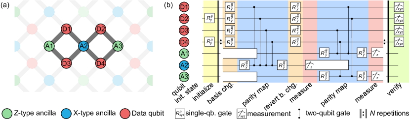
In the surface code, as in any stabilizer code, errors are detected by observing changes in the stabilizer measurement outcomes. Such syndromes are typically measured by entangling the stabilizer operators with the state of ancilla qubits, which are then projectively measured to yield the stabilizer outcomes. The surface code consists of a grid of data qubits with ancilla qubits, each connected to up to four data qubits Fowler et al. (2012). The code can detect errors and correct up to errors per cycle of stabilizer measurements. In particular, the stabilizers of the surface code, see Fig. 1, are given by
| (1) |
For the code-distance , it is only possible to detect a single error per round of stabilizer measurements and once an error is detected, the error can not be unambiguously identified, e.g. one would obtain the same syndrome outcome for an -error on D1 and on D3.
Here, we use the following logical qubit operators
| (2) | |||
| (3) |
such that the code space in terms of the physical qubit states is spanned by the logical qubit states
| (4) | |||
| (5) |
To encode quantum information in the logical subspace, we initialize the data qubits in a separable state, chosen such that after a single cycle of stabilizer measurements and conditioned on ancilla measurement outcomes being , the data qubits are encoded into the target logical qubit state. In this work, we demonstrate this probabilistic preparation scheme for the logical states , , and and we perform repeated error detection on these states.
Implementation
The seven qubit surface code, as discussed above, can be realized with a set of qubits laid out as depicted in Fig. 1(a). The logical qubit is encoded into four data qubits, D1-D4, and three ancilla qubits, A1, A2 and A3 are used to measure the three stabilizers , and , respectively. We initially herald all qubits in the -state Johnson et al. (2012); Ristè et al. (2012) and subsequently prepare the data qubits in a product state using single qubit rotations around the -axis. These initial states are then projected onto the code space after the initial stabilizer measurement cycles.
We perform the stabilizer measurement by first applying basis change pulses () on the data qubits to map the basis to the basis. Then we perform the entangling gates as in Fig. 1(b) and finally we revert the basis change. The measurement of A2 will therefore yield the -state (-state) corresponding to the eigenvalue () of the stabilizer . While the measurement pulse for A2 is still being applied, we perform the and stabilizer measurements simultaneously using the ancilla qubits A1 and A3, respectively. To avoid unwanted interactions during entangling gate operations, we operate the surface code using a pipelined approach similar to the scheme introduced by Versluis et.al. Versluis et al. (2017), for which we perform -type and -type stabilizer measurements sequentially, see Fig. 1(b) and Appendix A. The cycle is repeated after this step, and, after stabilizer measurement cycles, we perform state tomography of the data qubits.
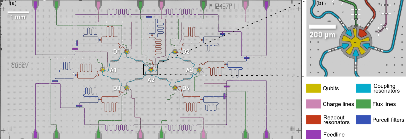
The gate sequence described above is implemented on the seven qubit superconducting quantum device shown in Fig. 2(a), see Appendix B for device parameters. Each qubit (yellow) is a single-island transmon qubit Koch et al. (2009) and features an individual flux line (green) for frequency tuning and an individual charge line (pink) for single qubit gates. Additionally, each qubit is coupled to a readout resonator (red) combined with an individual Purcell filter (blue). The Purcell filters protect against qubit decay into the readout circuit Reed et al. (2010) and suppress readout crosstalk such that multiplexed ancilla measurements can be performed without detrimental effects on the data qubits Heinsoo et al. (2018). Each Purcell filter is coupled to a feedline and we perform all measurements by probing each feedline with a frequency-multiplexed readout pulse Heinsoo et al. (2018), see Appendix C for a complete characterization of the readout. The qubits are coupled to each other via 1.5 mm long coplanar waveguide segments (cyan) as displayed in Fig. 1(a). The seven qubit surface code requires the central ancilla qubit to connect to four neighbors. The qubit island shape, shown Fig. 2(b), is designed to facilitate coupling to a readout resonator and four two-qubit couplers. To ensure a closed ground plane around the qubit island, each coupler element crosses the ground plane with an airbridge (white). We install the device in a cryogenic measurement setup Krinner et al. (2019), see Appendix D, and we characterize and benchmark the device using time-domain and randomized benchmarking methods as detailed in Appendix B.
Results
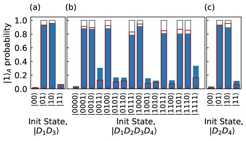
Changes in the outcome of repeated stabilizer measurements, also referred to as syndromes, signal the occurrence of an error. It is, thus, critical to directly verify the ability to measure the multi-qubit stabilizers using the ancilla readout Takita et al. (2016). We characterize the performance of the stabilizer measurements by preparing the data qubits in each of the computational basis states and measure the -stabilizers, see Fig. 3. For each stabilizer, the other ancilla qubits and unused data qubits are left in the ground state. We correctly assign the ancilla measurement outcome corresponding to the prepared basis state with success probabilities of , and for the stabilizers , and calculated as the overlap between the measured probabilities and the ideal case (gray wireframe in Fig. 3). Master equation simulations, which include decoherence and readout errors, are shown by the red wireframes in Fig. 3. The parity measurements are mainly limited by the relaxation of the data qubits, which directly leads to worse results for states with multiple excitations such as the -state when measuring . Further variations in the correct parity assignment probability arise due to the differences in qubit lifetimes and two-qubit gate durations (see Appendix B).
In a next step, we prepare logical states by projecting the data qubits onto the desired code space. We use a probabilistic encoding scheme, where we initialize the data qubits in a given product state and perform one cycle of stabilizer measurements. Then, in the events where all syndrome results are , the data qubits are projected onto the desired logical state. We can use this probabilistic scheme to prepare any logical state by initializing the state , which will be projected onto the (unnormalized) logical state . Here, we specifically initialize the logical states , , and by performing one cycle of stabilizer measurements on the states , , and , respectively, with .
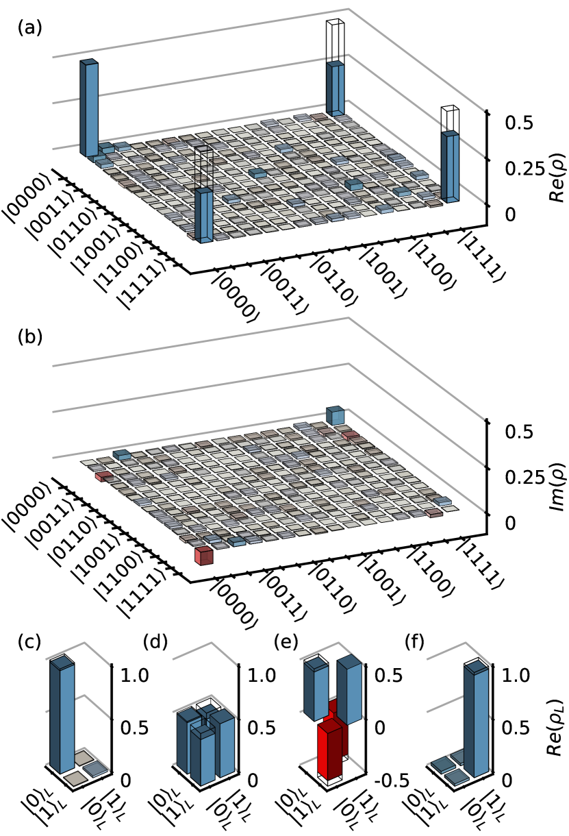
First, we consider the preparation of for which the data qubit state after one cycle of stabilizer measurements is projected onto the state when all ancilla qubits are measured in . We measure all ancilla qubits to be in the state with a success-probability of 25.1%, compared to an expected probability of 50% in the ideal case. To verify the state preparation, we perform full state tomography of the four data qubits after the completion of one cycle of stabilizer measurements and construct the density matrix based on a maximum likelihood estimation taking readout errors into account. The measured density matrix of the physical data qubits has a fidelity of to the target state, see Fig. 4(a-b). While the infidelity is dominated by qubit decoherence, we also observe small residual coherent phase errors as seen by the finite imaginary matrix elements in Fig. 4(b) corresponding to a phase error of 5 degrees accumulated over the cycle time of 1.92 s or, equivalently, a frequency drift of 7 kHz for any qubit.
Given access to the full density matrix, we can project it onto the logical qubit subspace for . Here. is the probability of the prepared state to be within the logical subspace, which is also referred to as the acceptance probability Takita et al. (2017) or yield Linke et al. (2017). The state is the logical qubit state, conditioned on the prepared state residing in the code space at the end of the cycle. In general, the physical fidelity of the data qubits can be expressed in the form , where is the fidelity of compared to the ideal logical state. We experimentally find the probability of the prepared state to be within the logical subspace. From simulations, we understand that the reduced mainly arises from decoherence during the stabilizer measurement cycle. After the projection onto the code space, the logical qubit state is described by a single qubit density matrix, see Fig. 4(c), which has a fidelity of to the ideal logical state. Similarly, we prepare the logical states , and , shown in Fig. 4(d-f), with logical state fidelities of 94.2%, 94.8% and 97.3%, respectively. The corresponding logical fidelities of the four logical states from master equation simulations are 98.5%, 96.6%, 96.4% and 98.1%, see Appendix E. The slightly lower fidelities for the and states arise from the pure dephasing of the data qubits making -errors during the encoding more likely than -errors.
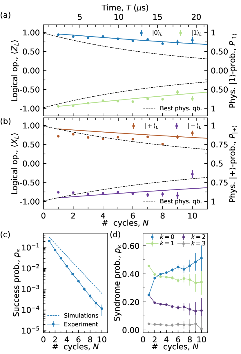
Next, we demonstrate repeated quantum error detection of any single error, which is a key ingredient of quantum error correction schemes such as the surface code. We do so by repeatedly measuring the expectation value of the encoded qubit’s logical () operator conditioned on having detected no error in any repetition of the stabilizer measurement and on having the final measurement of the data qubits satisfy (). This latter condition ensures that the qubits have remained in the logical subspace during the last detection cycle. We find that the expectation value (green and blue data points) decays in good approximation exponentially from unity with a logical life time of s from this exponential fit, which exceeds the life time, 16.8 s, of the best physical qubit (dashed lines) of the device, see Fig. 5(a). The logical expectation values are evaluated after the th cycle at time s shown at the top axis of Fig. 5(a,b). The approximately exponential decay of the logical qubit expectation value (brown and purple points) indicates a logical coherence time s, also exceeding that of the best physical qubit, 21.5 s, on the device (dashed lines), Fig. 5(b). However, the fits to show larger error bars due to the finite fidelity of preparing the logical and states, limited by the pure dephasing of the qubits as also seen in Fig. 4(d-e). Converting the measured decay times into an error per stabilizer measurement cycle, we find a logical error probability of and a logical error probability of .
Generally, we find good agreement between the measured expectation values of the logical qubit operators and the ones calculated using numerical simulations, solid lines in Fig. 5(a,b), accounting for finite physical qubit life- () and coherence times (), residual- coupling and readout errors, see Appendix E for details. From the numerical simulations, we extract logical decay times of s and s for and operators when no errors are detected, which are smaller than the experimentally obtained times, but within the experimental error bars. The simulated decay times correspond to a logical error probability of 4.2% and a logical error probability of 3.1% per error detection cycle. We suspect that for the -state coherent errors from qubit frequency drifts during the data collection cause the deviations between data and simulations.
Finally, we discuss the probability to observe ancilla qubits simultaneously in the state per error detection cycle when no errors were detected in previous cycles. We find that the probability to observe no errors slowly increases with from about 40% to 50%, see Fig. 5(d). From numerical simulations, we find that the probability to observe no additional errors after one cycle is between 49.9% and 50.3% per cycle, slightly larger than the experimentally observed values. We also observe experimentally that the probability of detecting more than a single ancilla qubit in the state per cycle is approximately suppressed exponentially. Consistent with this analysis, we find that the measured probability of not detecting an error (blue data points) decreases exponentially with , Fig. 5(c). After cycles, the success probability, i.e. the total probability that the state remained in the code space, approaches , around a factor of 6 smaller than the simulated value. The difference between the simulated (dashed line) and experimentally determined success probabilities stems from the smaller simulated error probability per cycle discussed above.
Discussion
In conclusion, we have implemented a seven qubit surface code for repeated quantum error detection. In particular, our experiment was enabled by fast and low-crosstalk readout for ancilla measurements. Using the seven qubit surface code, we demonstrated preparation of the logical states , , and with an average fidelity in the logical subspace of 96.1%. The probability to be within the logical subspace was found to be around 70% due to the accumulated errors during the stabilizer measurement cycle in good agreement with the corresponding numerical simulations. When executing the quantum error detection sequence for multiple cycles, we find an extended lifetime and coherence time of the logical qubit conditioned on detecting no errors. The data presented here is postselected on the ancilla measurement outcomes and on the condition that the final measurement of the data qubits satisfies the stabilizer conditions of the code. Crucially, since we found both extended logical life- and coherence time, we verified that neither the syndrome measurements nor the postselection extract information about the logical quantum state. The techniques used in this work for high-fidelity gates Rol et al. (2019) and low-crosstalk qubit readout Heinsoo et al. (2018) are directly applicable to a range of error correction codes Bacon (2006); Bombin and Martin-Delgado (2006); Chamberland et al. (2019); Li et al. (2019) which also critically require repeated measurements of ancilla qubits with minimal detrimental effects on the data qubits. Our implementation uses a gate sequence that is extensible to large surface codes Versluis et al. (2017) and, thus, our work represents a key demonstration towards using superconducting quantum devices for fault-tolerant quantum computing.
Data availability statement
The data produced in this work is available from the corresponding author upon reasonable request.
Acknowledgments
The authors are grateful for valuable feedback from K. Brown and A. Darmawan. The authors acknowledge contributions to the measurement setup from S. Storz, F. Swiadek and T. Zellweger.
The authors acknowledge financial support by the Office of the Director of National Intelligence (ODNI), Intelligence Advanced Research Projects Activity (IARPA), via the U.S. Army Research Office grant W911NF-16-1-0071, by the National Centre of Competence in Research Quantum Science and Technology (NCCR QSIT), a research instrument of the Swiss National Science Foundation (SNSF), by the EU Flagship on Quantum Technology H2020-FETFLAG-2018-03 project 820363 OpenSuperQ, by the SNFS R’equip grant 206021-170731 and by ETH Zurich. The views and conclusions contained herein are those of the authors and should not be interpreted as necessarily representing the official policies or endorsements, either expressed or implied, of the ODNI, IARPA, or the U.S. Government.
Author Contributions
C.K.A. designed the device and A.R., S.K., G.N. and M.G fabricated the device. C.K.A., A.R., S.L. and N.L. developed the experimental control software. C.K.A., A.R., S.K. and N.L. installed the experimental setup. C.K.A., A.R. and S.L. characterized and calibrated the device and the experimental setup. C.K.A. carried out the main experiment and analyzed the data. C.K.A. performed the numerical simulations. C.E. and A.W. supervised the work. C.K.A., A.R. and S.L. prepared the figures for the manuscript. C.K.A. wrote the manuscript with input from all co-authors.
Competing interests
The authors declare no competing interests.
Supplementary Information
Appendix A Pulse sequence
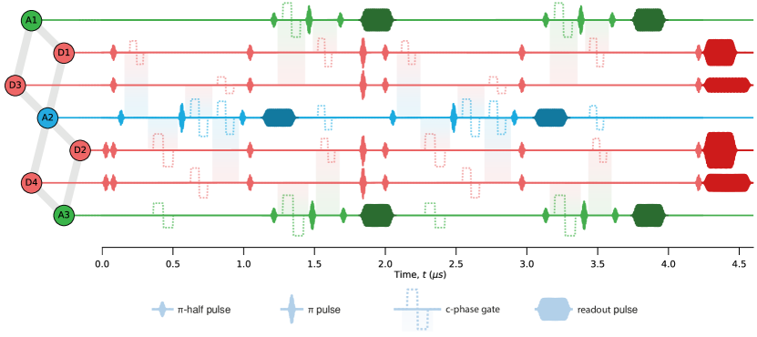
We physically implement the gate sequence shown in Fig. 1 by waveforms on the arbitrary waveform generators (AWGs) of the experimental setup, see Fig. 6 for an example with two cycles of stabilizer measurements. The pulse sequence includes dynamical decoupling pulses on the ancilla qubits during the stabilizer measurements and dynamical decoupling pulses on the data qubits in between each stabilizer cycle. All qubits are parked at their upper sweetspot which enable us to use the net-zero flux pulse shape as introduced by Rol et.al. Rol et al. (2019). The net-zero pulse is shaped such that the integral of the pulse is zero which serves to limit memory effects on the two-qubit gates e.g. due to charge accumulation in the flux lines. Beyond the flux pulses that enable the two-qubit gates (indicated with the shaded background), we apply additional flux pulses to non-interacting qubits. These additional flux pulses serves the purpose of pushing the frequency of the qubit down in frequency such that we avoid frequency collisions during the gate.
| D1 | D2 | D3 | D4 | A1 | A2 | A3 | |
|---|---|---|---|---|---|---|---|
| Qubit frequency, (GHz) | 5.494 | 5.712 | 4.108 | 4.222 | 4.852 | 4.963 | 5.190 |
| Lifetime, (s) | 11.2 | 8.7 | 8.7 | 16.3 | 5.7 | 16.8 | 11.8 |
| Ramsey decay time, (s) | 18.2 | 14.4 | 4.3 | 21.5 | 8.5 | 16.7 | 9.9 |
| Readout frequency, (GHz) | 6.611 | 6.838 | 5.832 | 6.063 | 6.255 | 6.042 | 6.299 |
| Readout linewidth, (MHz) | 7.5 | 10.6 | 6.0 | 7.2 | 17.3 | 10.9 | 11.0 |
| Purcell filter linewidth, (MHz) | 47.6 | 46.4 | 13.6 | 49.2 | 56.3 | 68.1 | 46.4 |
| Purcell-readout coupling, (MHz) | 20.0 | 22.2 | 17.5 | 18.4 | 18.8 | 18.7 | 19.0 |
| Purcell-readout detuning, (MHz) | 33.8 | 25.7 | 19.4 | 32.3 | 11.3 | 25.6 | 20.6 |
| Dispersive shift, (MHz) | -2.5 | -2.5 | -0.75 | -1.0 | -1.25 | -2.4 | -2.0 |
| Thermal population, () | 0.06 | 0.04 | 0.8 | 0.8 | 0.08 | 0.4 | 0.6 |
| Individual readout assignment prob. (%) | 99.4 | 99.2 | 97.8 | 98.2 | 98.7 | 98.8 | 98.8 |
| Multiplexed readout assignment prob. (%) | 98.9 | 99.1 | 98.2 | 97.4 | 97.7 | 98.4 | 98.6 |
| Measurement efficiency, | 0.30 | 0.24 | 0.15 | 0.15 | 0.20 | 0.27 | 0.22 |
Appendix B Device Fabrication and Characterization
The device in Fig. 2 consists of seven qubits coupled to each other in the geometry showed in Fig. 1(a). The resonator, coupling and qubit structures are defined using photolithography and reactive ion etching from a 150 nm thin niobium film sputtered onto a high-resistivity intrinsic silicon substrate. To establish a well-connected ground plane, we add airbridges to the device. Airbridges are also used to cross signal lines, i.e., for the flux and charge lines to cross the feedlines. The aluminum-based Josephson junctions of the qubits are fabricated using electron beam lithography.
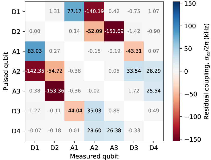
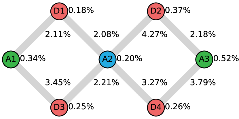
We extract the qubit parameters, see Table 1, using standard spectroscopy and time domain methods. In addition to the parameters characterizing individual qubits, we measure the residual -coupling between all qubit pairs, see results in Fig. 7, by performing a Ramsey experiment on the measured qubit with the pulsed qubit in either the or state. To characterize the gate performance, we implement randomized benchmarking on all qubits to find the error per single qubit Clifford and we perform interleaved randomized benchmarking for the characterization of errors per conditional-phase gate. The resulting gate errors are shown in Fig. 8. By directly measuring the -state population after the randomized benchmarking sequences, we further extract leakage per gate Wood and Gambetta (2018); Chen et al. (2016). For single qubit gates, we find a leakage per Clifford operation to be on average while the leakage per conditional-phase gate is between and .
Appendix C Readout Characterization
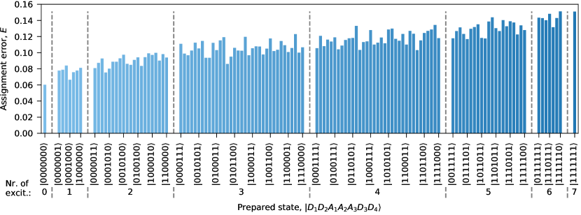
We perform multiplexed readout as detailed in Ref Heinsoo et al. (2018). Our readout scheme allows us to selectively address any subset of qubits. The readout is performed with a 200 ns readout pulse and a 300 ns integration window for qubits D1, D2, A1, A2 and A3 and a 300 ns readout pulse with a 400 ns integration window for qubits D3 and D4 due to the smaller dispersive shifts for these qubits. In Fig. 9, we show single-shot readout errors for all computational basis states of the seven qubits with an average assignment error of 11%.
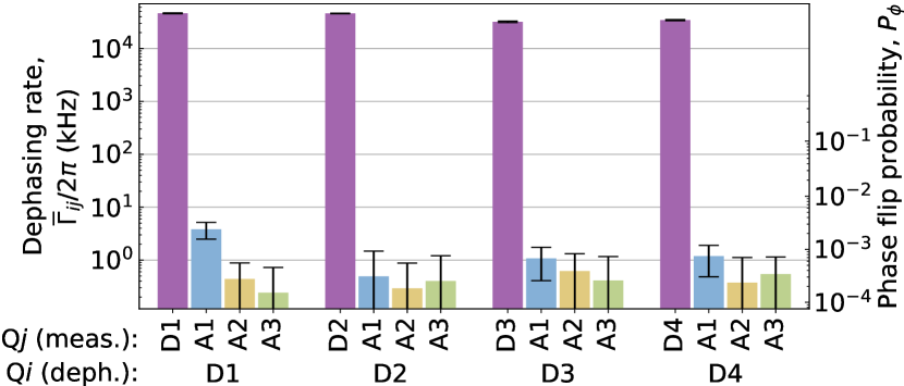
To characterize measurement induced dephasing on the data qubits when reading out the ancilla qubits, we perform a Ramsey experiment on each of the data qubits. We interleave the Ramsey pulses with a readout on qubit Q Heinsoo et al. (2018), and in Fig. 10 we show the resulting additional dephasing rates, , on the data qubits introduced by readout pulses. We can convert the dephasing rates to a probability for introducing a phase error by , where is the readout time. We find that measurements of the ancilla qubits induce less than 0.3% phase error on any data qubits.
Appendix D Experimental setup
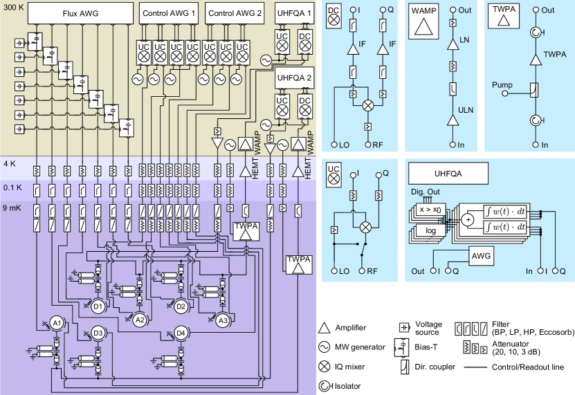
The seven qubit device is installed at the base plate of a cryogenics setup Krinner et al. (2019), see Fig. D. Here, the qubits (indicated by their labels) are controlled by flux and control AWGs through a series of microwave cables each with attenuators and filters, such as bandpass filters (BP), lowpass filters (LP), high pass fiters (HP) and eccosorb filters, installed as indicated. The flux pulses and microwave drive pulses are generated using arbitrary waveform generators (AWG) with 8 channels and a sampling rate of 2.4 GSa/s. The flux pulses are combined with a DC current using a bias-tee. The baseband microwave control pulses are generated at an intermediate frequency (IF) of MHz and then upconverted to microwave frequencies using IQ mixers installed on upconversion boards (UC). The multiplexed readout pulses, see also Appendix C, are generated and detected using an FPGA based control system (Zurich Instruments UHFQA) with a sampling rate of 1.8 GSa/s. The measurement signals at the outputs of the sample are amplified using a wide bandwidth near-quantum-limited traveling wave parametric amplifier (TWPA) Macklin et al. (2015) connected to isolators at its input and output. Moreover, we installed bandpass filters in the output lines to suppress amplifier noise outside the bandwidth of interest. The output signals are further amplified by high-electron-mobility transistor (HEMT) amplifiers and additional amplifiers at room temperature (WAMP). After amplification, the signals are downconverted (DC) and processed using the weighted integration units of the UHFQAs.
Appendix E Numerical Simulations
We model the dynamics of our seven qubit quantum system by a master equation given by
| (6) |
where is the density matrix describing the system at time and is the Hamiltonian, the time-dependence of which models the applied gate sequence. The collapse operators model incoherent processes. We solve the master equation numerically Johansson et al. (2013). To simplify the description of the system’s time evolution, we consider the Hamiltonian to be piece-wise constant, see details in Ref. Andersen et al. (2019). In addition, we include the Hamiltonian
modeling the residual coupling shown in Fig. 7. The incoherent errors are described by the Lindblad terms in Eq. (6) with
where and are the lifetime and decoherence time (Ramsey decay time) of qubit .
To simulate the ancilla measurement, we consider the POVM operators:
| (7) | ||||
| (8) |
for the outcomes 0 and 1 respectively, where are the experimentally determined probabilities for measuring the state when preparing the state . We choose for simplicity the POVM operators corresponding to minimal disturbance measurements Wiseman and Milburn (2010) as these POVM operators will mostly remove coherences similar to the real physical measurements. We evaluate the probability for each ancilla measurement outcome by for . The resulting density matrix given a certain measurement outcome is calculated as .
References
- Zhang et al. (2017) J. Zhang, G. Pagano, P. W. Hess, A. Kyprianidis, P. Becker, H. Kaplan, A. V. Gorshkov, Z.-X. Gong, and C. Monroe, “Observation of a many-body dynamical phase transition with a 53-qubit quantum simulator,” Nature 551, 601 (2017).
- Bernien et al. (2017) Hannes Bernien, Sylvain Schwartz, Alexander Keesling, Harry Levine, Ahmed Omran, Hannes Pichler, Soonwon Choi, Alexander S. Zibrov, Manuel Endres, Markus Greiner, Vladan Vuletić, and Mikhail D. Lukin, “Probing many-body dynamics on a 51-atom quantum simulator,” Nature 551, 579–584 (2017).
- Arute et al. (2019) Frank Arute, Kunal Arya, Ryan Babbush, Dave Bacon, Joseph C. Bardin, Rami Barends, Rupak Biswas, Sergio Boixo, Fernando G. S. L. Brandao, David A. Buell, Brian Burkett, Yu Chen, Zijun Chen, Ben Chiaro, Roberto Collins, William Courtney, Andrew Dunsworth, Edward Farhi, Brooks Foxen, Austin Fowler, Craig Gidney, Marissa Giustina, Rob Graff, Keith Guerin, Steve Habegger, Matthew P. Harrigan, Michael J. Hartmann, Alan Ho, Markus Hoffmann, Trent Huang, Travis S. Humble, Sergei V. Isakov, Evan Jeffrey, Zhang Jiang, Dvir Kafri, Kostyantyn Kechedzhi, Julian Kelly, Paul V. Klimov, Sergey Knysh, Alexander Korotkov, Fedor Kostritsa, David Landhuis, Mike Lindmark, Erik Lucero, Dmitry Lyakh, Salvatore Mandrà, Jarrod R. McClean, Matthew McEwen, Anthony Megrant, Xiao Mi, Kristel Michielsen, Masoud Mohseni, Josh Mutus, Ofer Naaman, Matthew Neeley, Charles Neill, Murphy Yuezhen Niu, Eric Ostby, Andre Petukhov, John C. Platt, Chris Quintana, Eleanor G. Rieffel, Pedram Roushan, Nicholas C. Rubin, Daniel Sank, Kevin J. Satzinger, Vadim Smelyanskiy, Kevin J. Sung, Matthew D. Trevithick, Amit Vainsencher, Benjamin Villalonga, Theodore White, Z. Jamie Yao, Ping Yeh, Adam Zalcman, Hartmut Neven, and John M. Martinis, “Quantum supremacy using a programmable superconducting processor,” Nature 574, 505–510 (2019).
- Preskill (2018) John Preskill, “Quantum Computing in the NISQ era and beyond,” Quantum 2, 79 (2018).
- Cory et al. (1998) D. G. Cory, M. D. Price, W. Maas, E. Knill, R. Laflamme, W. H. Zurek, T. F. Havel, and S. S. Somaroo, “Experimental quantum error correction,” Phys. Rev. Lett. 81, 2152–2155 (1998).
- Chiaverini et al. (2004) J. Chiaverini, D. Leibfried, T. Schaetz, M. D. Barrett, R. B. Blakestad, J. Britton, W. M. Itano, J. D. Jost, E. Knill, C. Langer, R. Ozeri, and D. J. Wineland, “Realization of quantum error correction,” Nature 432, 602–605 (2004).
- Schindler et al. (2011) Philipp Schindler, Julio T. Barreiro, Thomas Monz, Volckmar Nebendahl, Daniel Nigg, Michael Chwalla, Markus Hennrich, and Rainer Blatt, “Experimental repetitive quantum error correction,” Science 332, 1059–1061 (2011).
- Lanyon et al. (2013) B. P. Lanyon, P. Jurcevic, M. Zwerger, C. Hempel, E. A. Martinez, W. Dür, H. J. Briegel, R. Blatt, and C. F. Roos, “Measurement-based quantum computation with trapped ions,” Phys. Rev. Lett. 111, 210501 (2013).
- Linke et al. (2017) N. M. Linke, M. Gutierrez, K. A. Landsman, C. Figgatt, S. Debnath, K. R. Brown, and C. Monroe, “Fault-tolerant quantum error detection,” Science Advances 3, 10 (2017).
- Yao et al. (2012) Xing-Can Yao, Tian-Xiong Wang, Hao-Ze Chen, Wei-Bo Gao, Austin G. Fowler, Robert Raussendorf, Zeng-Bing Chen, Nai-Le Liu, Chao-Yang Lu, You-Jin Deng, Yu-Ao Chen, and Jian-Wei Pan, “Experimental demonstration of topological error correction,” Nature 482, 489–494 (2012).
- Bell et al. (2014) B. A. Bell, D. A. Herrera-Marti, M. S. Tame, D. Markham, W. J. Wadsworth, and J. G. Rarity, “Experimental demonstration of a graph state quantum error-correction code,” Nat. Commun. 5, 3658 (2014).
- Cramer et al. (2016) J. Cramer, N. Kalb, M. A. Rol, B. Hensen, M. S. Blok, M. Markham, D. J. Twitchen, R. Hanson, and T. H. Taminiau, “Repeated quantum error correction on a continuously encoded qubit by real-time feedback,” Nat. Commun. 7, 11526 (2016).
- Reed et al. (2012) M. D. Reed, L. DiCarlo, S. E. Nigg, L. Sun, L. Frunzio, S. M. Girvin, and R. J. Schoelkopf, “Realization of three-qubit quantum error correction with superconducting circuits,” Nature 482, 382–385 (2012).
- Shankar et al. (2013) S. Shankar, M. Hatridge, Z. Leghtas, K. M. Sliwa, A. Narla, U. Vool, S. M. Girvin, L. Frunzio, M. Mirrahimi, and M. H. Devoret, “Autonomously stabilized entanglement between two superconducting quantum bits,” Nature 504, 419–422 (2013).
- Ristè et al. (2015) D. Ristè, S. Poletto, M.-Z. Huang, A. Bruno, V. Vesterinen, O.-P. Saira, and L. DiCarlo, “Detecting bit-flip errors in a logical qubit using stabilizer measurements,” Nat. Commun. 6, 6983 (2015).
- Kelly et al. (2015) J. Kelly, R. Barends, A. G. Fowler, A. Megrant, E. Jeffrey, T. C. White, D. Sank, J. Y. Mutus, B. Campbell, Y. Chen, Z. Chen, B. Chiaro, A. Dunsworth, I.-C. Hoi, C. Neill, P. J. J. O’Malley, C. Quintana, P. Roushan, A. Vainsencher, J. Wenner, A. N. Cleland, and J. M. Martinis, “State preservation by repetitive error detection in a superconducting quantum circuit,” Nature 519, 66 (2015).
- Córcoles et al. (2015) A. D. Córcoles, Easwar Magesan, Srikanth J. Srinivasan, Andrew W. Cross, M. Steffen, Jay M. Gambetta, and Jerry M. Chow, “Demonstration of a quantum error detection code using a square lattice of four superconducting qubits,” Nat. Commun. 6, 6979 (2015).
- Ofek et al. (2016) Nissim Ofek, Andrei Petrenko, Reinier Heeres, Philip Reinhold, Zaki Leghtas, Brian Vlastakis, Yehan Liu, Luigi Frunzio, S. M. Girvin, L. Jiang, Mazyar Mirrahimi, M. H. Devoret, and R. J. Schoelkopf, “Extending the lifetime of a quantum bit with error correction in superconducting circuits,” Nature 536, 441–445 (2016).
- Ristè et al. (2013) D. Ristè, M. Dukalski, C. A. Watson, G. de Lange, M. J. Tiggelman, Y. M. Blanter, K. W. Lehnert, R. N. Schouten, and L. DiCarlo, “Deterministic entanglement of superconducting qubits by parity measurement and feedback,” Nature 502, 350–354 (2013).
- Negnevitsky et al. (2018) V. Negnevitsky, M. Marinelli, K. K. Mehta, H.-Y. Lo, C. Flühmann, and J. P. Home, “Repeated multi-qubit readout and feedback with a mixed-species trapped-ion register,” Nature 563, 527–531 (2018).
- Andersen et al. (2019) Christian Kraglund Andersen, Ants Remm, Stefania Balasiu, Sebastian Krinner, Johannes Heinsoo, Jean-Claude Besse, Mihai Gabureac, Andreas Wallraff, and Christopher Eichler, “Entanglement stabilization using ancilla-based parity detection and real-time feedback in superconducting circuits,” npj Quantum Information 5, 69 (2019), arXiv:1902.06946 [quant-ph] .
- Bultink et al. (2019) C. C. Bultink, T. E. OBrien, R. Vollmer, N. Muthusubramanian, M. W. Beekman, M. A. Rol, X. Fu, B. Tarasinski, V. Ostroukh, B. Varbanov, A. Bruno, and L. DiCarlo, “Protecting quantum entanglement from qubit errors and leakage via repetitive parity measurements,” arXiv:1905.12731 (2019).
- Nigg et al. (2014) D. Nigg, M. Müller, E. A. Martinez, P. Schindler, M. Hennrich, T. Monz, M. A. Martin-Delgado, and R. Blatt, “Quantum computations on a topologically encoded qubit,” Science 345, 302–305 (2014).
- Gong et al. (2019) M. Gong, X. Yuan, S. Wang, Y. Wu, Y. Zhao, C. Zha, S. Li, Z. Zhang, Q. Zhao, Y. Liu, F. Liang, J. Lin, Y. Xu, H. Deng, H. Rong, H. Lu, S. C. Benjamin, C. Peng, X. Ma, Y. Chen, X. Zhu, S. C. Pan, J.enjamin, C. Peng, X. Ma, Y. Chen, X. Zhu, and J. Pan, “Experimental verification of five-qubit quantum error correction with superconducting qubits,” arXiv:1907.04507 (2019).
- Takita et al. (2017) Maika Takita, Andrew W. Cross, A. D. Córcoles, Jerry M. Chow, and Jay M. Gambetta, “Experimental demonstration of fault-tolerant state preparation with superconducting qubits,” Phys. Rev. Lett. 119, 180501 (2017).
- Hu et al. (2019) L. Hu, Y. Ma, W. Cai, X. Mu, Y. Xu, W. Wang, Y. Wu, H. Wang, Y. P. Song, C.-L. Zou, S. M. Girvin, L.-M. Duan, and L. Sun, “Quantum error correction and universal gate set operation on a binomial bosonic logical qubit,” Nature Physics (2019).
- Campagne-Ibarcq et al. (2019) P. Campagne-Ibarcq, A. Eickbusch, S. Touzard, E. Zalys-Geller, N. E. Frattini, V. V. Sivak, P. Reinhold, S. Puri, S. Shankar, R. J. Schoelkopf, L. Frunzio, M. Mirrahimi, and M. H. Devoret, “A stabilized logical quantum bit encoded in grid states of a superconducting cavity,” arXiv:1907.12487 (2019).
- Fowler et al. (2012) Austin G. Fowler, Matteo Mariantoni, John M. Martinis, and Andrew N. Cleland, “Surface codes: Towards practical large-scale quantum computation,” Phys. Rev. A 86, 032324 (2012).
- Lidar and Brun (2013) Daniel A. Lidar and Todd A. Brun, Quantum Error Correction (Cambridge University Press, 2013).
- Terhal (2015) Barbara M. Terhal, “Quantum error correction for quantum memories,” Rev. Mod. Phys. 87, 307–346 (2015).
- Groen et al. (2013) J. P. Groen, D. Rista, L. Tornberg, J. Cramer, P. C. de Groot, T. Picot, G. Johansson, and L. DiCarlo, “Partial-measurement backaction and nonclassical weak values in a superconducting circuit,” Phys. Rev. Lett. 111, 090506 (2013).
- Schmitt et al. (2014) V. Schmitt, X. Zhou, K. Juliusson, B. Royer, A. Blais, P. Bertet, D. Vion, and D. Esteve, “Multiplexed readout of transmon qubits with Josephson bifurcation amplifiers,” Phys. Rev. A 90, 062333 (2014).
- Jeffrey et al. (2014) E. Jeffrey, D. Sank, J. Y. Mutus, T. C. White, J. Kelly, R. Barends, Y. Chen, Z. Chen, B. Chiaro, A. Dunsworth, A. Megrant, P. J. J. O’Malley, C. Neill, P. Roushan, A. Vainsencher, J. Wenner, A. N. Cleland, and J. M. Martinis, “Fast accurate state measurement with superconducting qubits,” Phys. Rev. Lett. 112, 190504 (2014).
- Heinsoo et al. (2018) Johannes Heinsoo, Christian Kraglund Andersen, Ants Remm, Sebastian Krinner, Theodore Walter, Yves Salathé, Simone Gasparinetti, Jean-Claude Besse, Anton Potočnik, Andreas Wallraff, and Christopher Eichler, “Rapid high-fidelity multiplexed readout of superconducting qubits,” Phys. Rev. Applied 10, 034040 (2018).
- Barends et al. (2014) R. Barends, J. Kelly, A. Megrant, A. Veitia, D. Sank, E. Jeffrey, T. C. White, J. Mutus, A. G. Fowler, B. Campbell, Y. Chen, Z. Chen, B. Chiaro, A. Dunsworth, C. Neill, P. OḾalley, P. Roushan, A. Vainsencher, J. Wenner, A. N. Korotkov, A. N. Cleland, and John M. Martinis, “Superconducting quantum circuits at the surface code threshold for fault tolerance,” Nature 508, 500–503 (2014).
- Rol et al. (2019) M. A. Rol, F. Battistel, F. K. Malinowski, C. C. Bultink, B. M. Tarasinski, R. Vollmer, N. Haider, N. Muthusubramanian, A. Bruno, B. M. Terhal, and L. DiCarlo, “Fast, high-fidelity conditional-phase gate exploiting leakage interference in weakly anharmonic superconducting qubits,” Phys. Rev. Lett. 123, 120502 (2019).
- Versluis et al. (2017) R. Versluis, S. Poletto, N. Khammassi, B. Tarasinski, N. Haider, D. J. Michalak, A. Bruno, K. Bertels, and L. DiCarlo, “Scalable quantum circuit and control for a superconducting surface code,” Phys. Rev. Applied 8, 034021 (2017).
- Johnson et al. (2012) J. E. Johnson, C. Macklin, D. H. Slichter, R. Vijay, E. B. Weingarten, John Clarke, and I. Siddiqi, “Heralded state preparation in a superconducting qubit,” Phys. Rev. Lett. 109, 050506 (2012).
- Ristè et al. (2012) D. Ristè, J. G. van Leeuwen, H.-S. Ku, K. W. Lehnert, and L. DiCarlo, “Initialization by measurement of a superconducting quantum bit circuit,” Phys. Rev. Lett. 109, 050507 (2012).
- Koch et al. (2009) J. Koch, V. E. Manucharyan, M. H. Devoret, and L. I. Glazman, “Charging effects in the inductively shunted Josephson junction,” (2009).
- Reed et al. (2010) M. D. Reed, B. R. Johnson, A. A. Houck, L. DiCarlo, J. M. Chow, D. I. Schuster, L. Frunzio, and R. J. Schoelkopf, “Fast reset and suppressing spontaneous emission of a superconducting qubit,” Appl. Phys. Lett. 96, 203110 (2010).
- Krinner et al. (2019) S. Krinner, S. Storz, P. Kurpiers, P. Magnard, J. Heinsoo, R. Keller, J. Lütolf, C. Eichler, and A. Wallraff, “Engineering cryogenic setups for 100-qubit scale superconducting circuit systems,” EPJ Quantum Technology 6, 2 (2019).
- Takita et al. (2016) Maika Takita, A.D. Córcoles, Easwar Magesan, Baleegh Abdo, Markus Brink, Andrew Cross, Jerry M. Chow, and Jay M. Gambetta, “Demonstration of weight-four parity measurements in the surface code architecture,” Phys. Rev. Lett. 117, 210505 (2016).
- Bacon (2006) Dave Bacon, “Operator quantum error-correcting subsystems for self-correcting quantum memories,” Phys. Rev. A 73, 012340 (2006).
- Bombin and Martin-Delgado (2006) H. Bombin and M. A. Martin-Delgado, “Topological quantum distillation,” Phys. Rev. Lett. 97, 180501 (2006).
- Chamberland et al. (2019) C. Chamberland, G. Zhu, T. J. Yoder, J. B. Hertzberg, and A. W. Cross, “Topological and subsystem codes on low-degree graphs with flag qubits,” arXiv:1907.09528 (2019).
- Li et al. (2019) Muyuan Li, Daniel Miller, Michael Newman, Yukai Wu, and Kenneth R. Brown, “2d compass codes,” Phys. Rev. X 9, 021041 (2019).
- Wood and Gambetta (2018) Christopher J. Wood and Jay M. Gambetta, “Quantification and characterization of leakage errors,” Phys. Rev. A 97, 032306 (2018).
- Chen et al. (2016) Zijun Chen, Julian Kelly, Chris Quintana, R. Barends, B. Campbell, Yu Chen, B. Chiaro, A. Dunsworth, A. G. Fowler, E. Lucero, E. Jeffrey, A. Megrant, J. Mutus, M. Neeley, C. Neill, P. J. J. O’Malley, P. Roushan, D. Sank, A. Vainsencher, J. Wenner, T. C. White, A. N. Korotkov, and John M. Martinis, “Measuring and suppressing quantum state leakage in a superconducting qubit,” Phys. Rev. Lett. 116, 020501 (2016).
- Macklin et al. (2015) C. Macklin, K. O’Brien, D. Hover, M. E. Schwartz, V. Bolkhovsky, X. Zhang, W. D. Oliver, and I. Siddiqi, “A near-quantum-limited Josephson traveling-wave parametric amplifier,” Science 350, 307–310 (2015).
- Johansson et al. (2013) J. R. Johansson, P. D. Nation, and Franco Nori, “QuTiP 2: A Python framework for the dynamics of open quantum systems,” Comput. Phys. Commun. 184, 1234–1240 (2013).
- Wiseman and Milburn (2010) H. Wiseman and G. Milburn, Quantum Measurement and Control (Cambridge University Press, 2010).