Dynamics of reconfigurable artificial spin ice: towards magnonic functional materials
Abstract
Over the past few years, the study of magnetization dynamics in artificial spin ices has become a vibrant field of study. Artificial spin ices are ensembles of geometrically arranged, interacting magnetic nanoislands, which display frustration by design. These were initially created to mimic the behavior in rare earth pyrochlore materials and to study emergent behavior and frustration using two-dimensional magnetic measurement techniques. Recently, it has become clear that it is possible to create artificial spin ices, which can potentially be used as functional materials. In this Perspective, we review the resonant behavior of spin ices (which is in the GHz frequency range), focusing on their potential application as magnonic crystals. In magnonic crystals, spin waves are functionalized for logic applications by means of band structure engineering. While it has been established that artificial spin ices can possess rich mode spectra, the applicability of spin ices to create magnonic crystals hinges upon their reconfigurability. Consequently, we describe recent work aiming to develop techniques and create geometries allowing full reconfigurability of the spin ice magnetic state. We also discuss experimental, theoretical, and numerical methods for determining the spectral response of artificial spin ices, and give an outlook on new directions for reconfigurable spin ices.
I Introduction
Artificial spin ices are superlattices composed of interacting magnetic nanoislands placed in a geometrical arrangement Heyderman and Stamps (2013). Originally, artificial spin ices were intended as macroscopic model systems mimicking the atomic frustration in rare earth pyrochlores Wang et al. (2006), with the advantage that their state could be directly measured using two-dimensional magnetic measurement techniques. Artificial spin ices were defined for crystallographic planes in the pyrochlores, leading to two fundamental arrangements: the square Wang et al. (2006) and the kagome Castelnovo et al. (2008) lattices. Despite this dimensional reduction, artificial spin ices exhibit massively degenerate ground states Heyderman and Stamps (2013) whose energy can be minimized by magnetic field-driven and thermal relaxation protocols Morgan et al. (2011); Farhan et al. (2013); Sklenar et al. (2019). Building on these successes, artificial spin ices evolved into superlattices designed to explore geometric frustration, free from the crystallographic constraints of pyrochlore materials. Myriad of novel artificial spin ices emerged Gilbert et al. (2014, 2016); Wang et al. (2016); Gliga et al. (2017); Sklenar et al. (2019); Luo et al. (2019); Saccone et al. (2019) featuring an interplay between frustration and topology Nisoli et al. (2017).
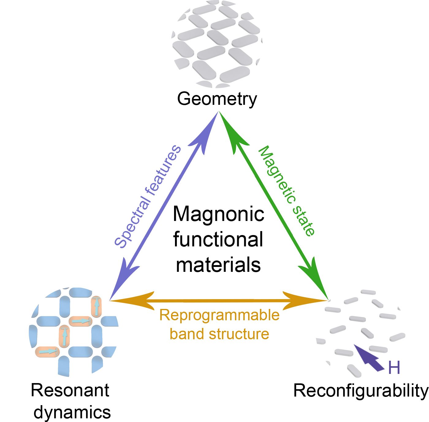
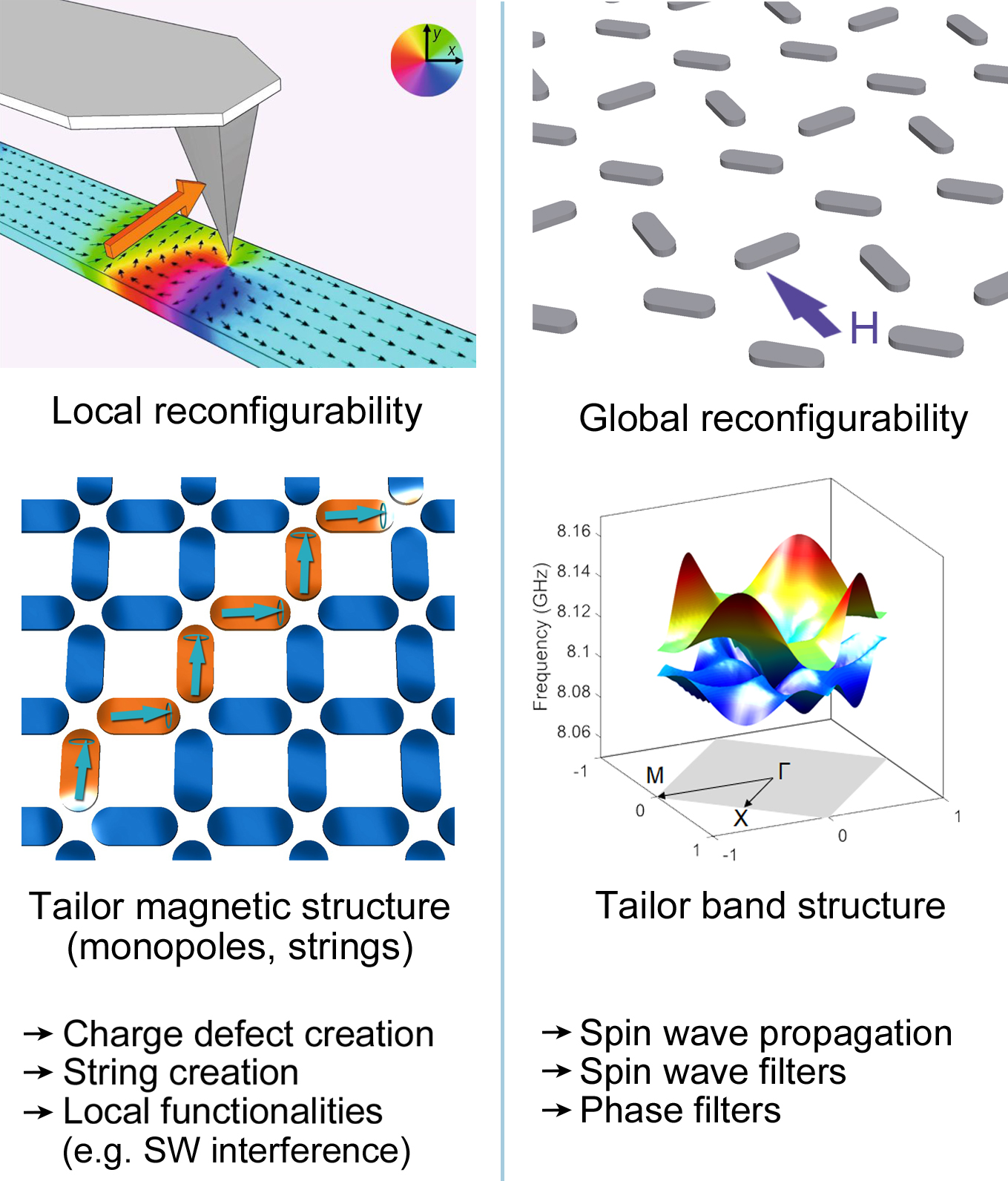
A subject of recent interest is the study of artificial spin ices in the context of magnetization dynamics. As superlattices, artificial spin ices are natural analogues of magnonic crystals Nikitov et al. (2001); Kruglyak et al. (2010); Lenk et al. (2011); Demokritov and Slavin (2013); Chumak et al. (2015), where spin waves are functionalized for logical applications by means of band structure engineering. Indeed, there is a growing interest in using spin waves (magnons) in information technology and computingChumak (2019). This interest stems from the need for disruptive concepts requiring significantly lower energy consumption than traditional CMOS-based technology, in which information is processed using charge currents that dissipate significant power. A key to achieving useful functionalities in magnonic crystals is the ability to reconfigure their magnetic state Grundler (2015). The geometric frustration and degeneracy of ground states of artificial spin ices in principle make artificial spin ices strong candidates for reconfigurable magnonics. In addition, the possibility of patterning virtually any planar geometry allows the definition of structures exhibiting both reconfigurable magnetic states and rich magnetization dynamics. These elements are essential for the creation of magnonic functional materials with a reprogrammable band structure, as illustrated in Fig. 1.
In this Perspective article, we briefly review the progress made in the understanding and control of spin waves in artificial spin ices. We survey methods to reconfigure artificial spin ices, theoretical models, experimental techniques, and salient advances in the study of magnetization dynamics in artificial spin ices. We discuss a number of outstanding challenges and perspectives for achieving reconfigurable artificial spin ices. Finally, we describe perspectives for the use of artificial spin ices for magnonics applications. For an in-depth review of fabrication processes, recent developments in “connected” artificial spin ices, and prospects for artificial spin ices as frustrated superlattices, we refer the reader to recent reviews in Refs. Lendinez and Jungfleisch, 2019; Skjærvø et al., 2019.
II Spin ice reconfigurability
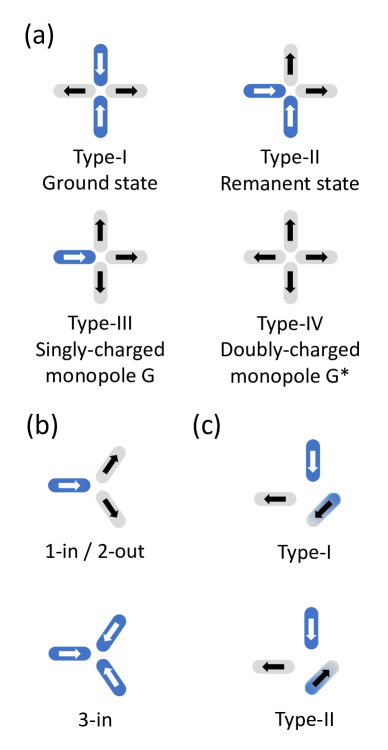
The first reports on artificial spin ices were on squareWang et al. (2006) and kagomeCastelnovo et al. (2008) ices. These systems are straight-forward to design as the unit cell contains a small number of elements. The relative simplicity of the lattices makes them attractive from the point of view of magnonic crystals. There is also considerable design freedom in that the nanoisland dimensions are decoupled from the lattice constant. This means that parameters, such as shape anisotropy and the magnetostatic coupling between elements, can be tuned independently to the extent allowed by lithographic limitations. Both lattices, however, suffer from the fact that their magnetic state is, in practice, often difficult to reconfigure. The square ice can be set in a well-defined remanent state by applying an external field along one of the array diagonals, resulting in a Type-II state, shown in Fig. 2(a). Moreover, the different nearest-neighbor distances between the four nanoislands at a vertex leads to non-equivalent interactions, the Type-I ground state is doubly-degenerate and can in principle be reached. However, the ground state is difficult to achieve using demagnetizing protocolsNisoli et al. (2007); Morgan et al. (2011) and is more readily achieved during thermal relaxation as demonstrated in Ref. Farhan et al., 2013, using very thin nanoislands (ca. 2 – 3 nm thick). It is also possible to attain the square ice Type-I ground state by raising the temperature above the Curie temperature, , of the magnetic elements and subsequently cooling down to room temperature Porro et al. (2013); Zhang et al. (2013a, 2019a). However, due to the rather high Curie temperature of Permalloy (ca. 870 K), which is typically used in artificial spin ices, annealing may lead to interdiffusion and loss of magnetism. Alternatively, the Curie temperature of the system can be lowered by tuning the material composition, as demonstrated using FePd in Ref. Morley et al., 2018.
While the kagome ice also has states with remanent magnetization that are relatively easy to obtain using external magnetic fields, in contrast to the square ice, the interactions between the three nanoislands at a vertex are degenerate, such that the global ground state could so far not be accessed, either through field-induced demagnetizing protocols or thermal relaxation Anghinolfi et al. (2015), but only through direct write of the magnetic state of each nanoelementGartside et al. (2018). Other frustrated lattices, such as Shakti lattices Morrison et al. (2013); Lao et al. (2018), similarly, are not easily configured into their ground states.
Consequently, defining spin ice geometries in which the magnetic state is fully reconfigurable is essential for magnonic applications. In this context, a different spin ice geometry, the charge ice, has recently been investigated by Wang et al. Wang et al. (2016). It consists in replacing specific nanoislands in the square ice with diagonally-oriented elements, while maintaining the locations of the magnetic charges (present at the extremities of the nanoislands) as in square ice. These geometric modifications result in great flexibility: they allow reconfiguring the entire lattice into eight distinct configurations with long-range order, using only an external uniform magnetic field applied at different angles. The equivalent Type-I and Type-II states are shown in Fig. 2(c).
The relative ease with which the charge ice can be reconfigured is clearly very attractive from the point of view of reconfigurable magnonic crystals. However, this reconfigurability comes at a price: the equivalence between the location of magnetic charges in the square and the charge ices imposes a condition on the relation between the length of the nanoislands and the center-to-center nanoisland separation :
| (1) |
As a consequence, the magnetostatic interactions cannot be tuned independently of the nanoisland shape anisotropy, irrespective of nanoisland size. In particular, even if significantly reducing the nanoisland size, which is bound by lithographic limits, the nanoisland separation will remain relatively large and the magnetostatic interactions between nanoislands will be weak. As an example, for nanoislands of dimensions 35 nm100 nm, the nanoisland separation is about 240 nm. Weak interactions between the nanoislands make magnon bands relatively flat with small or zero group velocities, and a weak dependence on the magnon spectrum on the magnetic configuration of the lattice. This is a serious impediment to using the charge ice as a reconfigurable magnonic crystal. We discuss possible solutions for enhancing inter-island coupling in SectionV.3.
III Experimental techniques
So far, the most versatile techniques for measuring resonant dynamics in artificial spin ices have been broadband ferromagnetic resonance (FMR) and Brillouin light scattering (BLS) spectroscopy. The main advantage of FMR is its relative ease of use. However, it lacks spatial resolution, and signal transmission is measured for large ensembles of nanoislands. Consequently, it does not allow, for example, the measurement of antisymmetric modes, in which oscillations of the magnetization with opposite phases cancel out and does not provide a spatial map of the magnetization dynamics. The magnetic structure needs to either be determined using other techniques such as magnetic force microscopy (MFM) Morgan et al. (2011); Zhang et al. (2013b) or transmission electron microscopy (TEM) Phatak et al. (2011); Li et al. (2019a), or through comparison with micromagnetic simulations. Microfocused BLS Sebastian et al. (2015), on the other hand, typically allows for the measurement of the mode spectrum with a spatial resolution of a few hundreds of nanometers, allowing to identify, e.g. edge and bulk modesLi et al. (2016a).
A number of other techniques can potentially be used for measuring magnetization dynamics in artificial spin ices and we expect that they will become more broadly used in the near future. In particular, X-ray based imaging exploiting the X-ray magnetic circular dichroism (XMCD) Schütz et al. (1987) effect has been employed to measure the evolution of the magnetic state during field-induced magnetization reversal Mengotti et al. (2011) as well as during thermal relaxation Arnalds et al. (2012); Farhan et al. (2013, 2014); Gliga et al. (2017). Time-resolved stroboscopic measurements taking advantage of the X-ray beam bunch structure currently achieve temporal resolutions below 100 psFinizio et al. (2018) and allow imaging spin wavesWintz et al. (2016); Förster et al. (2019); Albisetti et al. (2020). A pulsed or continuous wave excitation, phase-locked and time-delayed with respect to the photon bunches repetition frequency, is used to excite the magnetization precession. The response of the magnetization can thus be measured at different delay times Boero et al. (2009). So far, one of the main challenges of these types of dynamic measurements of spin ices has been achieving the spatial resolution required for detecting rather small variations of the magnetization on length scales of the order of a few tens of nanometers during resonant dynamics.
Recently, the stray field of an artificial spin ice was measured during magnetization reversal Wyss et al. using a nanometer-sized superconducting quantum interference device (SQUID) fabricated on the apex of a sharp quartz tip and integrated into a scanning SQUID microscope Finkler et al. (2010); Vasyukov et al. (2013, 2018). The lateral resolution, determined by the tip size, was sufficient to detect the magnetostatically-induced bending of the magnetization at the edges of individual nanoislands. Advantages of this technique include the possibility of combining sub-100 nm lateral resolution with field sensitivities of the order of a few tens of and the possibility of measuring in external magnetic fields up to 1 T. In principle, suitable modifications of the electronics and of the detection scheme should allow performing stroboscopic measurements, given that the Josephson junction typically has a characteristic frequency in the GHz range. Alternatively, scanning techniques using nitrogen-vacancy (NV)-based sensing Maletinsky et al. (2012); Rondin et al. (2012) have the advantage of working at room temperature and in ambient conditions.
Lateral resolutions of ca. 5 nm can in principle be obtained with aberration-corrected TEM McVitie et al. (2015); Li et al. (2019a). In this case, FMR measurements could be performed in-situ using specially designed holders Goncalves et al. (2017), while at the same time having the possibility to image and control the magnetic state.
IV Theoretical formulation
The magnetic configurations of ferromagnetic nanoislands in artificial spin ices and their collective dynamics are studied based on the Landau-Lifshitz-Gilbert (LLG) equation Gilbert (2004)
| (2) |
where is the gyromagnetic ratio, is the vacuum permeability, is the magnetization density vector, is the saturation magnetization density, and is a phenomenological, dimensionless magnetic damping parameter. This form assumes that , as is typically the case for physical systems. For numerical implementations, it is more convenient to rewrite the equation in the form originally proposed by Landau and Lifshitz Landau and Lifshitz (1953):
| (3) |
The effective field parametrizes the relevant physical terms contained in the energy . Typically, the effective field contributions used in artificial spin ices (and, indeed, in most micromagnetic simulations) are:
| (4) |
which includes exchange (), intrinsic anisotropy originating from crystalline spin-orbit coupling or from material structures such as layering, interfaces, or grain structures Stöhr and Siegmann (2006) (), an applied external field (), and nonlocal magnetostatic (e.g., dipolar) () fields.
The exchange field can be written as , where and is the Laplacian. The equation expresses the fact that the energy is minimized when the magnetization is collinear within a characteristic length, the exchange length , which is typically on the order of nm for metallic ferromagnets Stöhr and Siegmann (2006).
The magnetostatic field arises from volume charges and surface charges, due to the discontinuity of the normal component of the magnetization density at boundaries , where is an outward-pointing unit normal vector at an interface. In artificial square ices, magnetostatic interactions provide the main coupling mechanism between the nanoislands.
The LLG equation (2) subject to the effective field (4) is, in general, a system of coupled nonlinear partial differential equations. Analytical solutions are typically found in cases where the magnetostatic field is simplified, e.g., in the thin film limit where it reduces to a local field García-Cervera (1999). It must be noted that the effect of magnetostatic field is fundamental to describe the profile and dispersion of long-wave spin waves in thin films, so-called magnetostatic waves Stancil and Prabhakar (2009). Such spin waves have been instrumental in magnonics research Chumak et al. (2015). Consequently, numerical techniques are often required in order to solve the LLG equation.
IV.1 Micromagnetic simulations
Micromagnetic simulations Brown (1963) are the most common and powerful tool for solving the LLG equation based on finite-difference or finite-element techniques, while taking magnetostatics into account. The system of equations is stiff, which means that time-integration is usually done using implicit time-steppers as small errors in explicit schemes can easily grow exponentially. A recent review of computational micromagnetics can be found in Ref. Abert, 2019.
While artificial spin ices can be conceptually thought of as bar magnets Castelnovo et al. (2008), the magnetization within individual nanoislands is typically non-uniform Gliga et al. (2015); Jungfleisch et al. (2016). Thus, in order to simulate the properties of large arrays, a compromise has to be reached between spatial resolution and the spatial extent of the simulated domain. A common approach consists in reducing the artificial spin ice to a micromagnetic super-cell and imposing periodic boundary conditions, which mimic an infinite lattice. An accurate calculation of the static magnetic states can be obtained in this way Sklenar et al. (2019); Iacocca and Heinonen (2017). The same principle can be naturally extended to determine resonances Iacocca et al. (2016); Jungfleisch et al. (2016); Iacocca and Heinonen (2017); Iacocca et al. (2019); Dion et al. (2019). An alternative approach relies on simulating small artificial spin ice lattices, which include as many unit cells as computational resources allow, without periodic boundary conditions. This approach was for example used to determine the effect of topological defects Mengotti et al. (2009, 2011) on the dynamical spin wave spectrum of square ice Gliga et al. (2013). Reduced lattices have been also used to determine normal modes via the dynamical matrix method Grimsditch et al. (2004) and to study in detail the magnetostatic interaction between nanoislands, e.g., in pairs of nanoislands Dvornik et al. (2011), frustrated vertices Bang et al. (2019), and pinwheel artificial spin ices Paterson et al. (2019).
Micromagnetic simulations have been also used to probe magnetic transport in “connected” artificial spin ices, discussed in Ref. Lendinez and Jungfleisch, 2019.
IV.2 Semi-analytical models
The computational cost of micromagnetic simulations can be greatly reduced by analytical methods. While simple band structures can be found exactly in some cases, e.g. the well-known Bloch waves for free electrons in a periodic potential Balkanski and Wallis (2000), computing realistic band structures typically necessitate semi-analytical models.
Semi-analytical models require two key simplifications. First, the exchange field is considered to be negligible, assuming that the magnetization, , is approximately uniform within each nanoisland. Second, the magnetostatic field is treated as a dipole-dipole interaction between nanoislands with an effective field acting on nanoisland of the form:
| (5) |
The sum is performed over the whole lattice, is the volume of the magnetic element, and is the distance between two magnetic elements and . Note that care has to be taken when summing the long-range dipolar interactions over the entire lattice to ensure correct convergence. In Eq. (5), the magnetic elements can represent an entire nanoisland or subdivisions of a nanoisland. With this approximation, and assuming conservative dynamics (), the LLG equation reduces to the Larmor torque equation expressed as a set of vector, coupled, ordinary differential equations that are much simpler to treat analytically. This approach has been used in the context of magnetic nanodots Bondarenko et al. (2010); Verba et al. (2012); Lisenkov et al. (2016), Fe-intruded yttrium iron garnet (YIG) Shindou et al. (2013a), and “decorated” honeycomb lattices Shindou et al. (2013b).
A model that takes into account both the dipolar field and the edge canting of the magnetization in nanoislands was proposed in Ref. Iacocca et al., 2016. To this effect, a tight-binding-like approach is used to calculate the effective field acting on the artificial spin ice unit cell. Key to this process is the reduction of the long-range dipole-dipole field into intra-unit-cell and inter-unit-cell components. The latter can be pre-computed to desired numerical accuracy as detailed in the Appendix of Ref. Iacocca et al., 2016.
V Resonant magnetization dynamics
V.1 Square ice
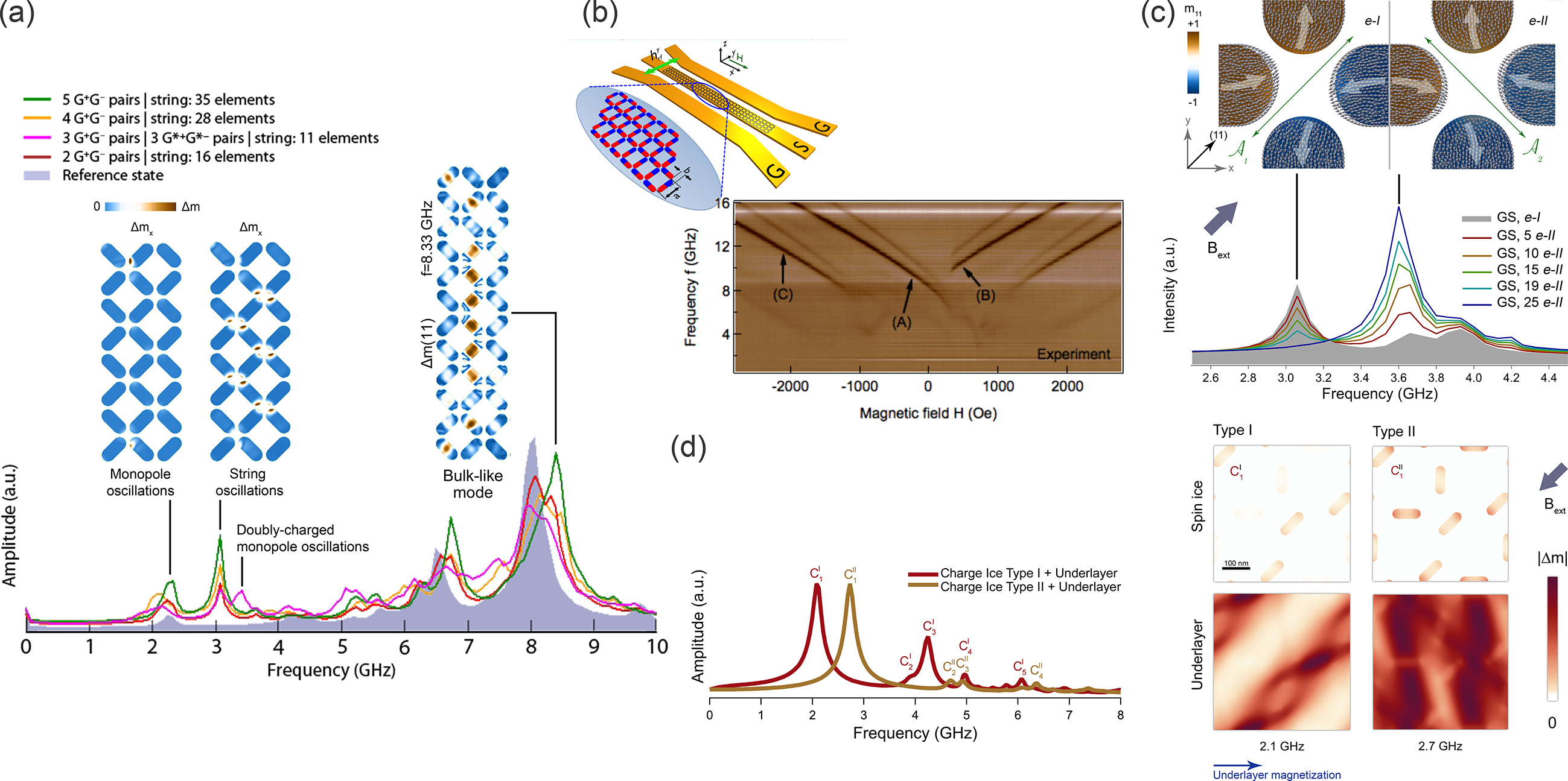
The magnetization dynamics in square ice was first investigated in Ref. Gliga et al., 2013, in particular the influence of topological defects on the resonant dynamics of the square ice. Such defects occur when the magnetization at a vertex is not in a two-in/two-out state (so-called ice rule, corresponding to Type-I and Type-II vertices), resulting for example in vertex states where the magnetization is in a one-in/three-out state (‘monopoles’ or Type-III vertices) or a even four-in state (doubly charged monopoles or Type-IV vertices), shown in Fig. 2(a). In the pyrochlore compounds, such defects have been found to display behavior similar to that of Dirac monopoles Castelnovo et al. (2008). These emergent monopoles occur in pairs (e.g., monopole-antimonopole) connected by a string, along which the magnetization is reversed with respect to a reference state. While it was known that these defects affect the equilibrium behavior and the magnetization reversal in spin ices Morgan et al. (2011); Phatak et al. (2011); Budrikis et al. (2012); Westphalen et al. (2008), Gliga et al.Gliga et al. (2013) found that each type of topological defect as well as the strings of reversed magnets connecting these defects display distinct and localized features, both spatially as well as in frequency, as summarized in Fig. 3(a). These features, in the GHz frequency range, thus act as fingerprints for each type of defect.
The resonant dynamics of long-range ordered square artificial spin ices were first investigated experimentally by Jungfleish et al. Jungfleisch et al. (2016). Using broadband FMR spectroscopy, they found a number of modes within a range between 4 GHz and 16 GHz as a function of in-plane magnetic field, shown in Fig. 3(b). Some of the lower-frequency modes disappeared or exhibited complex hysteretic behavior at low fields. Detailed comparison with micromagnetic simulations showed that the hysteresis in the mode spectrum was related to the magnetization configuration of particular nanoislands, resulting from the applied field history. The experimentally measured resonance spectroscopy was quantitatively described by a semi-analytical model for the Type-II configuration.
More recently, Ghosh et al. Ghosh et al. (2019) also experimentally investigated the resonant modes of square ices using FMR spectroscopy and the evolution of those modes as a function of nanoisland thicknesses. By comparing their experimental results with micromagnetic modeling, they could identify bulk-like as well as (symmetric) edge modes in the spectra. They also identified local configurations during magnetization reversal as well as topological defects, as predicted in Ref. Gliga et al., 2013. The resonant modes in square ice have been spatially mapped by Li et al. Li et al. (2016b) using micro-BLS. Recently, anti-spin ice systems consisting in thin films with geometrically-placed holes instead of nanoislands (analogous to antidots), have also been studied using BLS. These structures have been found to support frequency-dependent spin wave confinement in regions between holes Mamica et al. (2018).
Beyond macrostates, it has also been found that seemingly small variations in the magnetic state of individual elements could equally affect the magnetization dynamics. In particular, due to magnetostatics, in elements above a certain thickness (ca. 5–10 nm in Permalloy, depending on lateral dimensions and thickness) the magnetization state changes from an ‘onion’ state (mostly uniform) to C or S states in which the magnetization bends at the extremities of the element Rougemaille et al. (2013). These changes affect the magnetic symmetry of the vertices and the torques in the presence of an applied field, as shown in Fig. 3(c), resulting in distinct mode spectra for C and S configurations Gliga et al. (2015). Additionally, the presence of such internal degrees of freedom affects the thermal evolution of the system, giving rise to edge melting, in which the magnetization stochastically switches between the C and S states. This behavior is reflected in the mode spectrum of the thermal magnetization dynamics in the form of 1/-type flicker noise at low frequencies Gliga et al. (2015).
V.2 Kagome ice
The magnetization dynamics of kagome artificial spin ices were investigated experimentally by Dion et al. Dion et al. (2019) and based on micromagnetic simulations by Arroo et al. Arroo et al. (2018). In Ref. Dion et al. (2019), the patterned shape of the nanoislands, and thus the shape anisotropy, was altered in the three sublattices, such that the three-fold rotational symmetry was broken. Different resonant modes and responses could then be obtained by aligning an external magnetic field along the three inequivalent directions. Moreover, because of the different coercive fields of the nanoislands in the three sublattices, a variety of microstates could be obtained through the application of a magnetic field in different directions. These microstates were shown to have different spin wave spectra using micromagnetic modeling. In Ref. Arroo et al. (2018), the mode spectrum in kagome ice was investigated, demonstrating that the magnetic microstate influences the spin-wave spectra. In addition to mode shifting, the uniform mode can be strongly be enhanced or suppressed, thus allowing its activation and deactivation. The magnetization dynamics in a connected kagome lattice was studied by Bhat, Watanabe, Baumgaertl, and Grundler Bhat et al. (2019). Despite being connected, they showed that topological defect configurations gave rise to different, distinguishable dynamics, and that Dirac strings connecting two topological defects induced pronounced modifications in magnon frequencies.
V.3 Charge ice
The charge ice geometry, introduced in Section II, is based on square ice, and its global magnetic state is fully reconfigurable by applying magnetic fields at successive angles, in a well-defined order. The downside of this system is that the geometric constraints in building the lattice lead to largely spaced and, consequently, weakly coupled elements. Addition of an exchange biased magnetic underlayer Iacocca et al. (2019) has been shown to lead to interactions between the spin ice and the magnetic film that significantly modify the modes of the spin ice, in particular suppressing the amplitude of the bulk modes and leading to significant differences in the mode spectra of Type-I and Type-II states (spectra in Fig. 3d). In addition, coupling to the uniaxially anisotropic thin film gives rise to modes in the underlayer, two of which are shown in Fig. 3d, and can act as spin wave channels, similar to those present in antidot magnonic crystals Sklenar et al. (2013); Mamica et al. (2018).
V.4 Magnonic band structure
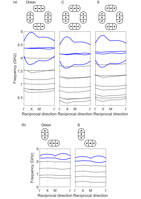
The magnon bands in square ices was investigated numerically by Iacocca, et al. Iacocca et al. (2016). Square ice in Type-I and Type-II states was considered and the effect of the magnetic state as well as of the edge bending of the magnetization on the magnon dispersions was determined. Figures 4(a) and 4(b) depict the magnon dispersion for the two configurations with the possible edge bending states. Clearly, the magnon bands in the Type-I and Type-II configurations are very different. The Type-I configuration has four bulk bands representative of the four nanoislands in the unit-cell, while the Type-II configuration with only two nanoislands in the unit-cell has two bulk bands. Second, the Type-II bands, in particular the bulk bands, are much flatter than the Type-I dispersive bulk bands with a much smaller forbidden gap than between the Type-I dispersive bulk bands. Beyond introducing a semi-analytical model for calculating the band structure, that work clearly demonstrated that square spin ices can be viewed as reconfigurable magnonic lattices. Toggling between magnetic states results in fundamentally different magnonic band structures.
An interesting, and presently relevant, question arising in the context of band structures is whether magnonic bands can be designed to be topologically non-trivial, and perhaps even toggled between topologically trivial and non-trivial band structures. In general, systems with topologically non-trivial band structures will necessarily exhibit edge modes at the interface with a topologically trivial structure. Perhaps the best known example are time-reversal-invariant topological insulators, which exhibit edge states in the gap. In the case of a topological insulator, the edge states have a specific spin-momentum locking so that, in the absence of impurities that break time-reversal invariance, the edge states propagate without scattering. In general, the topological edge states exhibit some kind of chirality coupling the propagation vector to some internal degree of freedom.
Shindou and co-workers Shindou et al. (2013a, b) theoretically examined periodic magnetic structures that can exhibit topologically non-trivial magnon bands. While the structures they considered are technically not artificial spin ices, they are nevertheless interesting to discuss in the context of magnonic lattices. The first considered structure Shindou et al. (2013a) was a yttrium iron garnet (YIG) thin film in which a periodic rectangular array of circular holes was introduced with lattice constants . The holes were filled with Fe. The key to obtaining topologically non-trivial magnon bands is that the dipolar interaction between the Fe cylinders can act analogously to the spin-orbit interaction and cause a gapped band inversion when the Fe cylinders are in a periodic array (as opposed to in a continuous film). When the unit-cell size becomes larger than a typical magnetic exchange length, a gap opens up and the lowest magnon band acquires a non-trivial topology. Reducing takes the system to a topological transition where the band gap closes and the two lowest magnon bands form Dirac cones at the band closing points. Shindou and co-workers also demonstrated that when the system is gapped with a non-trivial topology, chiral edge states form which propagate unidirectionally.
A second structure considered in Ref. Shindou et al., 2013b was a two-dimensional periodic array of square or honeycomb lattices of ferromagnetic particles. Here, the particles were assumed to be small enough such that each one could be treated as a single macrospin. In the presence of an external magnetic field perpendicular to the plane of the arrays, these arrays could admit magnon bands with non-trivial topologies with chiral edge modes.
An extension of the semi-analytical model in Ref. Iacocca et al., 2016 was used to investigate a square ice on top of a heavy metal thin film, such as Pt Iacocca and Heinonen (2017). It is well known that Py or other ferromagnetic thin films deposited on a heavy-metal spin-orbit scatterer, such as Pt, Pd, Ta, or W, leads to an interfacial Dzyaloshinskii-Moriya interaction (DMI)Fert and Levy (1980); Fert (1990); Thiaville et al. (2012); Yanes et al. (2013). The DMI allows for a chiral magnetization structureHeide et al. (2008); Bode et al. (2007). The principle demonstrated in Ref. Iacocca and Heinonen, 2017 was that the presence of DMI can lead to a topologically non-trivial magnon band structure in the square ice. Indeed, upon increasing the DMI strength, a band inversion can occur between the two lowest magnon bands forming Dirac cones with non-trivial topologies.
VI Perspectives
VI.1 Reconfigurability
As indicated in Fig. 1, one of the main challenges in using spin ices as reconfigurable magnonic lattices is finding a geometry whose magnetic state is easily reconfigurable and exhibits sufficiently strong magnetostatic interactions to generate rich dynamics. The square and kagome ices, along with modified geometries such as Shakti lattices can easily be reconfigured to a limited number of long-range ordered remanent states, using external fields. However, generally a large number of states, including the ground state, are difficult to access. Here, we discuss, solutions and perspectives to overcome this situation, including using local probes provided by scanning probe microscopy, spin transfer torques and lattice geometries.
Recently, Gartside et al. Gartside et al. (2016, 2018) used a high-moment magnetic force microscopy (MFM) tip to controllably reverse the magnetization in selected spin ice nanoislands. This tip acts as a monopole source when in close proximity to the magnetic nanostructures. As the tip is moved perpendicular to the long axis of the nanoisland, a domain wall pair is nucleated. As the tip completes its motion across the nanoisland, the domain walls move apart towards the opposite ends of the nanoisland, leaving a reversed magnetization behind. They consequently named this technique topological defect-driven magnetic writing. Reference Gartside et al., 2018 further demonstrated that it is possible to design configurations both in connected and magnetostatically coupled kagome spin ices, including the kagome ground state as well as more exotic out-of-equilibrium states. An MFM tip has also been used in Ref.Wang et al. (2016) to locally define the magnetic state of charge ice as well as in Ref.Lehmann et al. (2019) to define the magnetic state of individual elements in order to achieve different ferroto-toroidic states in an artificial spin ice structure forming an artificial magneto-toroidal crystal. While this technique is versatile, it also is rather slow as it hinges on mechanical motion of the tip. Other means of generating stray fields to nucleate domain walls can be envisioned, which do not rely on mechanical motion. As an example, Gartside et al. “envisage a system comprising a three-dimensional network of nanowires whereby current-controlled domain walls replace the magnetic force microscope tip, greatly enhancing flexibility, throughput and integration with existing technologies”. However, such schemes also present limits: as the size of the nanoislands shrinks close to the domain-wall width, the reversal of nanoislands becomes coherent (Stoner-Wohlfarth switching) rather domain-wall driven. An external field, whether generated by domain walls in nanowires or by other means, will have to be large enough to overcome the coercive field of the nanoislands, which can typically be larger than the field required to nucleate domain walls.
Another means of reconfiguring the magnetic state consists in using spin transfer torque (STT) to switch magnetic nanostructures and nanoislands. This effect is equally used in commercially available STT magnetic random access memories (STT-MRAMs)Apalkov et al. (2013). However, designing and realizing an artificial spin ice in which individual nanoislands are switched using STT requires complex deposition and patterning techniques. This can certainly be overcome in principle as for STT-MRAMs, but it would make reconfigurable artificial spin ices considerably more expensive and, perhaps, technologically out of range for academic laboratories. Another issue would be that stray fields from polarizing layers in STT devices would have to be mitigated. This can also in principle be done using, e.g. synthetic antiferromagnets as polarizing layers, but again would generate increasing complexity and cost.
A different avenue to reconfigure artificial spin ices is to explore new lattices that may allow for simpler protocols. As discussed in Sec. V.3, charge ice allows for reconfiguration using a saturating field along different directions at the price of reduced coupling between the nanoislands Wang et al. (2016). In contrast, it has been shown that strongly coupled nanoislands can support long-range order according to a well-defined phase diagram. Sklenar et al. Sklenar et al. (2019) investigated a quadrupole lattice that could support both ferro-quadrupolar and antiferro-quadrupolar long-range order. Long-range ordered states were observed after annealing without any applied field and a full phase diagram was computed by Monte Carlo simulations, establishing clear field and temperature transitions for the long-range ordered state, paramagnetic state, and their coexistence.
Another recently investigated geometry consists of a chiral pattern, obtained by rotating the elements in each vertex by 45∘. This chiral ice has been found to exhibit ratchet behavior during thermal relaxation Gliga et al. (2017). Indeed, following saturation, the net vertex magnetization rotates in a single direction (e.g. clockwise) during thermal relaxation at room temperature. Thus, while the magnetization dynamics is locally stochastic, globally it unfolds in a well-defined direction. The final magnetic state can be defined by using a weak bias field. While this allows a certain degree of reconfigurability, which may lead to the creation of functional materials, it also requires very thin magnets (ca. 2–3 nm thick) and it is not clear at present to which extent the resonant dynamics is interesting. Li et al. Li et al. (2019a) have used thicker nanoislands in the same pinwheel geometry and showed that it is possible to obtain well-defined configurations during field-induced magnetization reversal. These thicker elements equally exhibit edge bending of the magnetization Paterson et al. (2019); Wyss et al. , as well as chiral dynamics at the vertex level Wyss et al. and might possess rich spectral features. One of the main advantages of this geometry is that the ground state is ferromagnetic Macêdo et al. (2018) and can trivially be obtained through saturation in an external field. In addition, it is in principle possible to engineer physical defects in the lattice in order to achieve local control of the magnetic structure. In Ref. Drisko et al., 2016, physical defects such as a missing nanoisland accompanied by lattice distortion were introduced in square ice. Such defects have been found to lead to the formation of domain walls across ground state regions. In these systems, the spin ice cannot support continuous ground-state ordering, demonstrating that a single physical defect can alter the topology of the system, thus providing a possible path for tuning the magnetic ordering.
In a kagome lattice, Chopdekar et al. Chopdekar et al. (2013) tailored the shape anisotropy of specific nanoislands, and thus their switching fields, to achieve desired states with near perfect reliability.
Finally, we note that while magnonic response is confined to the GHz regime, artificial spin ice dynamics over a large range of frequencies still remains unexplored, ranging from the quasi-static measurements of hysteretic behavior or thermal relaxation (a few Hz) to a few GHz. For example, it has been proposed that using microwave assisted switching, it should be possible to facilitate the nucleation of certain types of defects in connected kagome ices Bhat et al. (2016), and AC fields could also be used for clocking atificical spin ice-based logic architectures Arava et al. (2018); Jensen et al. (2018).
VI.2 Intrinsic damping
Another challenge in realizing magnonic crystals with spin ice is due to the relatively large damping in ferromagnetic transition metals, such as Ni, Co, Fe, and their common inter-metallic alloys. This is a result of the spin-orbit interactions, which cause dephasing of the magnetization dynamics (see, for example, Skadsem et al. Skadsem et al. (2007)). For example, in Permalloy the value of the damping constant is of about 0.008 Liu et al. (2007). While this is small enough for a number of studies of magnetization dynamics, such as vortex motion in Permalloy disks, it still is sufficiently large that linear spin wave packets only propagate over distances of the order of a few hundred nanometers Madami et al. (2011) before being damped out, and magnetization dynamics is damped out within 5 nsLiu et al. (2007). This obviously limits applications such as logic devices, in which wave packet propagation is desirable over large distances, for example between features as well as to gate the propagation of the wave packets. An obvious possibility to extend the propagation length of spin waves is to use materials with smaller intrinsic damping. Relatively recently, it was discovered that the intermetallic CoFe alloy can have a very small intrinsic damping Schoen et al. (2016) of about . This occurs at a Co-concentration of about 25%, when the density-of-states at the Fermi energy has a sharp minimum which limits the scattering of electrons. This is of great interest as CoFe alloys can be deposited using a range of different techniques, including sputtering. Additionally, there is a long history of using CoFe alloys in academic and industrial research, as well as in industrial applications. Another advantage of CoFe alloys is their large magnetic moment: their polarization is over 2.0 T at this Co concentration. It is also important to keep in mind that at 25% Co, the alloy structure is bcc rather than fcc, with much larger magnetostriction and magnetocrystalline anisotropy than the fcc alloys.
Another material of interest is YIG, with a very low dimensionless damping of about . However, YIG is not easily grown in thin films and it is difficult to pattern. Recent advances in pulsed laser deposition have demonstrated YIG thin films of thickness down to 3.4 nmMendil et al. (2019). However, the saturation polarization is smaller, mT than its bulk value of about mT at room temperature for relatively thick films (90 nm). The saturation magnetization density decreases with in thin films, and decreases especially rapidly below 10 nm. Other possibilities are Heusler alloysFelser and Hirohata (2015), especially half-metallic L21 Heusler alloys such as Co2MnAl or Co2MnSiJourdan et al. (2014), which can exhibit very small damping.
We note that very low damping has recently been measured in magnetically soft epitaxial spinel NiZnAl ferrite thin films, which also exhibit strong magnetoelastic couplingEmori et al. (2017). Such materials potentially allow the development of spin–mechanical devices, opening a new route for realizing reconfigurable magnonic crystals.
VI.3 Coupling schemes
A number of interesting directions of research involve hybrid structures combining artificial spin ices with different systems. In Section V.3, we have described a heterostructure in which the charge ice was coupled to a soft magnetic thin underlayer as a means of increasing and modifying the interaction between the nanoislands. Other types of heterostructures can equally be used to define specific behavior and functionalities. Wang et al.Wang et al. (2018a) placed a charge ice on top of a Type-II superconducting thin film. The magnetic charges in the spin ice gave rise to stray fields that introduced a vortex lattice in the superconducting thin film. Using the ability to controllably reconfigure the charge ice, the state of the vortex lattice could be toggled between geometrically frustrated, highly degenerate vortex lattices, and non-frustrated ones. Different charge ice configurations gave rise to distinct transport properties, and Ref. Wang et al., 2018a demonstrated that this heterostructure can be used to realize reprogrammable superconducting electronic devices. Golovchanskiy et al.Golovchanskiy et al. (2019) also built a hybrid metamaterial structure of Nb and Py thin films. In their work, they showed that the diamagnetic response of the superconductor affected the magnon dispersion, and furthermore they could distinguish between the Meissner state of the superconductor (in which all magnetic flux is expelled) and the mixed state, in which penetrating flux gives rise to a vortex lattice. One can also envisage patterning artificial spin ices on top of Type-I superconductors. In these, the magnetic stray fields from the spin ice will not form vortices due to field penetration, as in Type-II superconductors. Instead, as long as the fields are below the critical field , the superconductor will act as a perfect magnetic mirror. This should radically change the magnetostatic interactions between the nanoislands as well as within the nanoislands, as shown by Golovchanskiy et al.Golovchanskiy et al. (2019). In addition to reconfiguring the magnetic state of the artificial spin ice, one could also drastically alter the magnetostatic interactions simply by changing the temperature of the superconductor, above or below the critical temperature.
Other exotic materials, in particular materials with topologically non-trivial electronic properties, exhibit interesting interactions with magnetic materials and magnetic fields which can in principle be exploited. For example, topological insulators Hasan and Kane (2010); Bansil et al. (2016); Kane and Mele (2005a, b); Bernevig et al. (2006); Fu et al. (2007); Moore and Balents (2007) with time-reversal symmetry have gapless topological surface states, which cannot backscatter due to spin-momentum locking and are (in principle) dissipationless. Spin-momentum locking can be also exploited in spintronics applications: for example, the topological surface states in the topological insulator Bi2Se3Xia et al. (2009); Zhang et al. (2009) were used to switch the magnetization Li et al. (2019b) of the insulating ferromagnet BaFe12O19. The switching efficiency at low temperatures was much higher than in Pt/BaFe12O19 heterostructures using spin orbit torques. In topological insulators such as Bi2Se3, the topological surface states are protected by time-reversal symmetry, and magnetic impurities that break this symmetry generally suppress or even destroy the topological surface states. But the question of how topological insulators and their topological surface states interact with lattices of magnetic charges is an interesting one. A further question is whether the topological surface states and their charge and spin transport properties can be manipulated using reconfigurable artificial spin ices. Other topological materials include Dirac and Weyl semimetalsArmitage et al. (2018). Dirac semimetalsWang et al. (2012); Liu et al. (2014); Young et al. (2012) are gapless, obey time-reversal and inversion symmetry, and have a number of Dirac cones that are doubly degenerate. Weyl semimetalsWan et al. (2011); Xu et al. (2011); Lv et al. (2015) can be obtained from Dirac semimetals by breaking either inversion or time-reversal symmetry; breaking either symmetry lifts the degeneracy of the Dirac cones, and each Dirac point separates into two non-degenerate Weyl nodes. Both Dirac and Weyl semimetals also admit surface states, Fermi arc states, which have specific spin-momentum lockings. While the Dirac Fermi arc states are protected by symmetry, the Weyl Fermi arc states are topologically protected and are more robust than the Dirac Fermi arc states. Weyl semimetals with broken time-reversal symmetry are in general magnetic and so respond to magnetic fields. This opens exciting directions for developing functional materials by combining magnetic Weyl semimetals with different materials. For example, heterostructures of magnetic Weyls exhibit an unusual inverse Edelstein effect, which converts a pure spin current to a charge currentZhang et al. (2019b); the unusual properties, such as a pronounced anisotropy, originate in the topological properties of the electronic states. It is thus likely that reconfigurable artificial spin ices could be combined with Dirac or Weyl semimetals to affect and manipulate the spin charge transport properties, especially of the Fermi arc states. Such heterostructures could possibly also be used to mediate interactions and entanglement of quantum states, thereby enabling new avenues for devices in quantum computing and quantum sensing.
VI.4 Three-dimensional structures
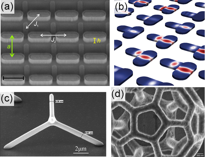
Recently, the possibility of creating three-dimensional (3D) structures using using e-beam lithography Kirchner and Schift (2015), two-photon lithographyMaruo et al. (1997) as well as focused electron beam induced deposition Keller et al. (2018); Fowlkes et al. (2018) has opened radically new possibilities for defining artificial spin systems. The use of the third dimension allows increased configurability and optimization of the magnetostatic interaction between different elements of the system. A recent example is the creation of 3D square ice, in which the two sublattices are separated by a height offset Perrin et al. (2016), shown in Fig. 5a. Such structures have permitted the realization of systems with extensive degeneracy and unbound monopoles Farhan et al. (2019), analogous to those found in the rare earth pyrochlore compounds Castelnovo et al. (2008). Indeed, while the magnetic moments in atomic spin ices are located at the vertices of a tetrahedral lattice, the artificial square ice is obtained by projecting these moments onto a plane, leading to unequal interactions between the four nanoislands. The height offset can be chosen such that it restores the equivalence of the magnetostatic interactions. In terms of magnetization dynamics, we expect such systems to offer further possibilities for tailoring the mode spectrum and the band structure in artificial spin ices, not only exploiting topological defects, but equally the offset in the third dimension as simulated in Fig. 5(b). Concurrently, more complex elementary structures have been created, which consist of connected bars and allow for the study of magnetic frustration in three dimensions. For example, the dynamics of ‘tetrapods’ such as in Fig. 5(c) has been investigated using the magneto-optical Kerr effect (MOKE), revealing that it is possible to measure localized oscillations of the magnetization in such structures. Larger and more complicated geometries, such as mesoscopic ’buckyballs’ (Fig. 5(d)) have recently been fabricatedDonnelly et al. (2015); Gliga et al. (2019) and their structure measured using X-ray ptychographic tomographyDonnelly et al. (2015). We expect that these proofs-of-concept will allow the development of novel materials combining specific mechanical and magnetic properties to create structures with reconfigurable functions. At the same time, dedicated techniques are necessary to measure the properties of such structures. Presently, tomography techniques are being actively developed, which allow probing 3D magnetic structures with X-raysStreubel et al. (2015); Donnelly et al. (2017); Witte et al. (2020), neutrons Manke et al. (2010) or electronsPhatak et al. (2014); Wolf et al. (2019). Very recently, stroboscopic time-resolved measurements of magnetization dynamics in 3D have been demonstrated based on magnetic laminographyDonnelly et al. (2020). Beyond X-rays, ferromagnetic resonance measurements of 3D objects have been made possible by employing microresonator loops Lenz et al. (2019). Ultimately, the combination of such techniques will enable the full structural and magnetic characterization of 3D structures.
VI.5 Modelling
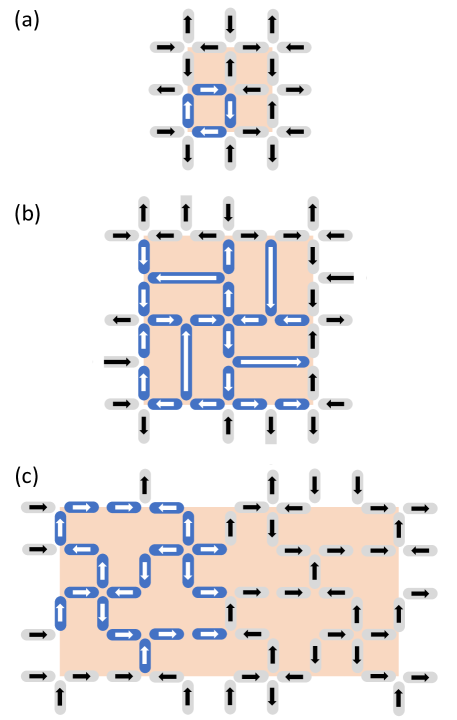
The plethora of experimental possibilities directly impacts the theoretical and numerical modelling of artificial spin ices. The interplay between short-range and long-range interactions discussed in section IV.1 imposes serious constraints on the feasibility of implementing numerical models with predictive power. The first issue to address is the growing size of the artificial spin ice unit-cell, which also increases the full size of the micromagnetic domain and may also increase the size of the micromagnetic super-cell when imposing periodic boundary conditions. For example, a Type-I square ice has a unit cell consisting of four nanoislands and a micromagnetic super-cell consisting of eight nanoislands (four whole and eight split by the periodic boundary conditions). We illustrate this in in Fig. 6(a) where the nanoislands in the unit cell are colored blue and the micromagnetic super-cell is indicated by the orange-shaded area. The reason why the number of nanoislands in the unit-cell and the super-cell do not coincide is that typical implementations of periodic boundary conditions require orthogonal translation vectors for the super-cell. Under such implementations, and using the same color-scheme in panels (b) and (c), we identify the unit-cell of a Shakti lattice Gilbert et al. (2014) and a Tetris lattice Gilbert et al. (2016), both in a long-range ordered state. We note that the magnetic states depicted in Fig. 6(b) and (c) do not correspond to the ground states identified, e.g., in Ref. Morrison et al., 2013 (see Figs. 8 and 10), but instead are illustrations of long-range ordered states with relatively simple unit-cells. The Shakti lattice in such a configuration has 20 nanoislands in both the unit-cell and the super-cell (12 whole and 16 split by the peridodic boundary conditions). The Tetris lattice in the configuration shown has 20 nanoislands in the unit-cell and 40 in the super-cell (32 whole and 16 split by the peridodic boundary conditions). These examples show that dynamic simulation of Shakti and Tetris lattices could increase the memory allocation fourfold and eightfold, respectively, compared to a Type-I square ice. In typical finite difference approaches Vansteenkiste et al. (2014) where the entire domain is discretized, such an increase in memory allocation will necessarily impose a lower bound on the cell-size (due to the finite amount of RAM), resulting in a poor spectral resolution of the modes. This suggests that at least some novel artificial spin ices may preferentially be modelled by finite element methods Gliga et al. (2013), where non-magnetic regions can be managed more efficiently to compute magnetostatic fields Abert (2019), in particular in combination with a boundary element method Schrefl et al. (2003). In addition, one can envision dedicated schemes including skewed periodic boundary conditions to allow for arbitrary translation vectors and thus equalize the super-cell to the unit-cell.
Another intriguing direction consists in using artificial intelligence methods to accelerate or complement micromagnetic modeling. Machine learning methods have recently been used to describe Stoner-Wohlfarth switching in single-domain particlesMiao (2019). This study employed supervised learning, in which machine learning models (random forest, support vector machine, and deep neural networks) were first trained on a large number of modeled examples of particles with different damping, anisotropy fields, external field strengths and directions, and the switching behavior predicted by the surrogate models were then validated against other modeling data sets. In another workExl et al. (2020), convolutional neural networks were used to construct a surrogate model for the time-stepping predictor in micromagnetic modeling of the LLG equation. The authors relied on dimensional reduction methods (principal component analysis) to reduce dimensions of the non-linear time-stepping problem. Unsupervised learning was then used to train a convolutional neural network which provided an estimator for time-stepping. The model was then applied to the micromagnetic benchmark problems 1 and 2 (see MAG micromagnetic modeling activity group: http://www.ctcms.nist.gov/ rdm/mumag.org.html). There exist several potential directions for employing artificial intelligence methods to the dynamics of artificial spin ices. One possibility is to replace the micromagnetic description of the internal dynamics of nanoislands by surrogate machine learning models. These can be constructed, for example, by supervised training of deep neural networks using modeled dynamics of a single nanoisland as training data. The gain would be dimensional reduction by eliminating all but a small number of internal degrees of freedom of the nanoislands, and the remaining problem would be that of the larger-scale inter-island interactions coupled to the surrogate models. Another direction would be to replace the long-range inter-nanoisland interactions with a machine-learning based surrogate model, thus reducing the problem to that of individual nanoislands coupled to an effective field given by a surrogate model.
Another limitation of micromagnetic simulations is that dynamic excitations are computed for collective modes () and periodic boundary conditions allow for the excitation of even wavevectors harmonically proportional to the super-cell size. Such short wavelenghts are essentially irrelevant for the artificial spin ice band structure defined within the first Brillouin zone. Under the constraint that increasing the super-cell size to contain many unit-cells is an unfeasible approach, novel schemes to compute Bloch wavesRychły et al. (2015a) must be found. A possible solution is to use semi-analytical models, such as in Ref. Iacocca et al., 2016, where a tight-binding-like approach was used to collapse the -dependent effective field into the unit-cell by invoking Bloch’s theorem. The solution is then obtained by solving an eigenvalue problem. For such an approach to be viable, it would be important to determine irreducible micromagnetic super-cells to avoid aliasing. Implementing this type of micromagnetic simulation would constitute a hybrid approach where the detailed micromagnetic structure informs the computation of an effective field acting on the super-cell from which the eigenmodes can be calculated. Admittedly, the computational efficiency of such a hybrid approach would be low, but it may be feasible to implement in situations requiring accuracy at the nanometer level.
To explore the Brilliouin zones in artificial spin ices, the semi-analytical model proposed in Ref. Iacocca et al., 2016 is an attractive method. Computation of the Brillouin Zones is achieved through an involved determination of the matrix elements in the eigenvalue problem and results in a coarse spatial mode resolution compared to micromagnetic simulations. Because the magnetization vector is recast in terms of a Holstein-Primakoff transformation Slavin and Tiberkevich (2009), i.e. a complex conjugate pair of dynamic variables, the resulting eigenvalue problem is of size , where is the number of considered macrospins in each nanoisland and is the number of nanoislands per unit-cell. Therefore, the growing complexity of artificial spin ices will lead to both complicated expressions for the matrix elements and dense matrices. However, this would be a one-time exercise, suggesting the possibility of developing a matrix library as a function of artificial spin ice geometry and magnetic state.
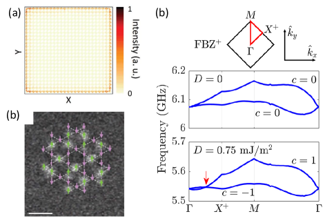
The predictive power of semi-analytical models is useful to explore the features of the first Brillouin zone. An interesting application is to determine the onset of topologically protected bands that can give rise to edge modes akin to surface conduction in topological insulators. Such “topological magnons” have been explored so far in two different contexts. One is the use of periodic lattices with broken symmetry Shindou et al. (2013a, b), as discussed in section V. Numerical demonstration of edge modes in a “decorated” honeycomb lattice Shindou et al. (2013b)is shown in Fig. 7(a). Similar ideas were explored in artificial spin ices in Ref. Iacocca and Heinonen, 2017, where a square ice coupled to a heavy metal substrate was modelled to investigate chiral effects induced by the interfacial Dyzaloshinskii-Moriya interaction (DMI) on the spin ice. The DMI parameter was used to toggle the onset of topological bands. As shown in Fig. 7(b), a non-zero parameter gives rise to a Dirac point indicated by a red arrow, and the concomitant change in the band’s Chern number, . The associated chirality in reciprocal space should lead to band inversion in the surface states, although no direct computation of this case has been presented. The use of DMI to induce chirality in ferromagnetic nanoislands has recently been demonstrated experimentally Luo et al. (2019). So far, only the static magnetization has been tuned to realize arbitrary structures including a kagome lattice depicted in Fig. 7(c). The dynamic behavior of such structures remains to be studied. It would indeed be interesting to excite spin waves in such systems and explore their topology as well as reconfigurability. A second approach to topological magnons has been to consider chirality on the atomic level. This is typically obtained in pyrochlore spin ices Zhang et al. (2013a) and in honeycombs lattices Chisnell et al. (2015). Recent studies have further shown the possiblity of toggling the chirality of edge modes by tuning the DMI to exchange interaction ratio Wang et al. (2018b) or by inducing DMI by time-dependent interactions, or Floquet engineering Owerre (2017); Wang et al. (2018b). The recently investigated kagome ice with nanoislands with varying anisotropies Dion et al. (2019) could be a starting point to explore the onset of topological bands by pattering the structure on a heavy metal or by studying the next-nearest-neighbors interactions between the nanoislands.
Other type of artificial spin ices can be deliberately designed to take advantage of broken long-range order. The initial work by Gliga et al. Gliga et al., 2013 explored precisely how topological defects in a square ice would impact the collective dispersion of waves. Similarly, it would be interesting to consider structures exhibiting collective, topological frustration Nisoli et al. (2017), and not only vertex frustration. This would allow exploring possible links between geometrical topology and the topological character of excited spin waves. Finally, quasi-crystals, i.e. ordered lattices without a well-defined spatial periodicity, are other types of structures, which have been explored in the context of magnonics Rychły et al. (2015b); Lisiecki et al. (2019) and in artificial spin ices Bhat et al. (2013); Shi et al. (2018). A predictive theoretical or numerical model of these artificial spin ices will no doubt be challenging to implement. Experiments will likely drive the need to develop numerically efficient techniques.
VI.6 Devices, logic, and information processing
In magnonicsKruglyak et al. (2010); Lenk et al. (2011); Demokritov and Slavin (2013); Chumak et al. (2015), spin waves are utilized as carriers of information for technologically relevant functions. One direction of research consists in exploring the design of logic gates and multiplexers based on spin-wave interferometryHertel et al. (2004); Schneider et al. (2008); Vogt et al. (2014) and the directional propagation of wavesVogt et al. (2012); Zakeri et al. (2010); Jamali et al. (2013); Otálora et al. (2016). In particular, this has led to the demonstration of NAND gatesHertel et al. (2004) as well as a three-terminal YIG-based magnonic transistorChumak et al. (2014). Another direction of research consists in the creation of periodically patterned, magnetostatically coupled nanostructures with feature sizes of the order of the magnon wavelength in which spin waves can propagate. These allow creating devices with tailored band structures, defining frequency ranges for which spin wave propagation is allowed and forbidden band gapsNikitov et al. (2001). Such structures, called magnonic crystals, in analogy to photonic crystals, potentially provide the basis for a wide range of magnon spintronic devices, including waveguides, signal filters, phase shifters and signal processing elements operating the GHz frequency rangeMelkov et al. (2006); Lee et al. (2009). Magnon-based applications are therefore compatible with the speeds of current CMOS-based circuits and, if antiferromagnetic magnons can be harnessed, this could even be pushed to the THz range. Furthermore, the band structure can be reprogrammed by exploiting different possible magnetic states in the unit cell of the periodic latticeChumak et al. (2009); Topp et al. (2010); Tacchi et al. (2010).
So far, artificial spin ices have shown potential for magnonic applications: they possess rich mode spectra, tunable band structures, which can be engineered to have non-trivial topologies in the presence of DMI and, when coupled to an underlayer, can in principle support spin wave propagation along defined channels. Going forward, these characteristics are essential for the development and demonstration of relevant building blocks for information transmission and detection, gating and switching, or logic devices. Generally, we expect such functionalities to be achieved in two ways. The first consists in tailoring the band structure through the geometry and magnetic state of the artificial spin ices to obtain desired functionalities required e.g. for spin wave filters, phase filters or to define spin wave propagation channelsIacocca et al. (2019). Achieving such functionalities requires the possibility of reconfiguring the global state of the artificial spin ice, such as by means of an external field. For practical devices, however, a more promising route is the use of voltage-controlled anisotropyMaruyama et al. (2009); Amiri and Wang (2012), which allows for magnetization switching using applied electric voltages. This would be much easier to engineer, as the building blocks for integration already exists, and it would also lead to smaller power consumption than the generation of magnetic fields. The second way consists in exploiting topological defects (e.g. ‘monopoles’) and the strings of reversed nanoislands connecting them in order to define regions with specific functions, such as spin wave interference. This hinges upon the possibility of locally reconfiguring the magnetic state of the artificial spin ices using techniques, such as tip-induced reversalGartside et al. (2018), local contacts for the injection of spin-polarized currents, or applied voltages through the use of voltage-controlled anisotropy. Such schemes will also have to allow for large-scale processing, which is in principle rather an engineering than a fundamental materials science problem – indeed, modern commercial spin transfer torque random access memories, for example, use processing technology compatible with CMOS technology. (For a recent review, see, for example, Ref. Hanyu et al., 2019).
Magnons can be generated in a number of different ways but the most likely path compatible with miniaturization and large-scale processing is using spin-torque oscillators (STOs). STOs can generate magnetic oscillations with frequencies between GHz to over tens of GHz that directly couple to the magnonic medium. Using low-damping materials, such as YIG, magnons can propagate macroscopic distances without significant attenuationChumak (2019). Detection of magnons should ideally be performed in a way that is compatible with large-scale integration, i.e. based on giant magnetoresistance or tunneling magnetoresistance, in which read-out elements are deposited on the magnetic medium. Artificial spin ices as reconfigurable magnonic lattices combine several functions that are necessary: they can be reconfigured to switch or multiplex information flow, and are not limited to information flow in only one direction. The nanoislands themselves can also be directly integrated with STOs for generation and detection as well as switching for local or global reconfiguration. Finally, the nanoislands can also serve as non-volatile memory element directly integrated into a magnonics-based IT and computing system.
Acknowledgments
S.G. is thankful to Armin Kleibert and Martino Poggio for discussions. O.G.H. was funded by the Department of Energy, Office of Science, Basic Energy Sciences Materials Sciences and Engineering Division. S.G. acknowledges funding by the European Union’s Horizon 2020 research and innovation program under the Marie Skłodowska-Curie grant agreement No. 708674 as well as funding from the Swiss National Science Foundation. The authors also are grateful for the computing resource support provided on Blues and Bebop, high-performance computing clusters operated by the Laboratory Computing Resource Center at Argonne National Laboratory, Use of the Center for Nanoscale Materials, an Office of Science user facility, was supported by the US Department of Energy, Office of Science, Office of Basic Energy Sciences, under Contract No. DE-AC02-06CH11357.
References
- Heyderman and Stamps (2013) L. J. Heyderman and R. L. Stamps, Journal of Physics: Condensed Matter 25, 363201 (2013).
- Wang et al. (2006) R. F. Wang, C. Nisoli, R. S. Freitas, J. Li, W. McConville, B. J. Cooley, M. S. Lund, N. Samarth, C. Leighton, V. H. Crespi, and P. Schiffer, Nature 439, 303 (2006).
- Castelnovo et al. (2008) C. Castelnovo, R. Moessner, and S. L. Sondhi, Nature 451, 42 (2008).
- Morgan et al. (2011) J. P. Morgan, A. Stein, S. Langridge, and C. H. Marrows, Nature Physics 7, 75 (2011).
- Farhan et al. (2013) A. Farhan, P. M. Derlet, A. Kleibert, A. Balan, R. V. Chopdekar, M. Wyss, J. Perron, A. Scholl, F. Nolting, and L. J. Heyderman, Phys. Rev. Lett. 111, 057204 (2013).
- Sklenar et al. (2019) J. Sklenar, Y. Lao, A. Albrecht, J. D. Watts, C. Nisoli, G.-W. Chern, and P. Schiffer, Nature Physics 15, 191–195 (2019).
- Gilbert et al. (2014) I. Gilbert, G.-W. Chern, S. Zhange, L. O’Brien, B. Foe, C. Nisoli, and P. Schiffer, Nature Physics 10, 670 (2014).
- Gilbert et al. (2016) I. Gilbert, Y. Lao, I. Carrasquillo, L. O’Brian, J. D. Watts, M. Manno, C. Leighton, A. Scholl, C. Nisoli, and P. Schiffer, Nature Physics 12, 162 (2016).
- Wang et al. (2016) Y.-L. Wang, Z.-L. Xiao, A. Snezhko, J. Xu, L. E. Ocoloa, R. Divan, J. E. Peason, G. W. Crabtree, and W.-K. Kwok, Science 352, 962 (2016).
- Gliga et al. (2017) S. Gliga, G. Hrkac, C. Donnelly, J. Büchi, A. Kleibert, J. Cui, A. Farhan, E. Kirk, R. V. Chopdekar, Y. Masaki, N. S. Bingham, A. Scholl, R. L. Stamps, and L. J. Heyderman, Nature Materials 16, 1106–1111 (2017).
- Luo et al. (2019) Z. Luo, T. P. Dao, A. Hrabec, J. Vijayakumar, A. Kleibert, M. Baumgartner, E. Kirk, J. Cui, T. Savchenko, G. Krishnaswamy, L. J. Heyderman, and P. Gambardella, Science 363, 1435 (2019).
- Saccone et al. (2019) M. Saccone, K. Hofhuis, Y.-L. Huang, S. Dhuey, Z. Chen, A. Scholl, R. V. Chopdekar, S. van Dijken, and A. Farhan, Phys. Rev. Materials 3, 104402 (2019).
- Nisoli et al. (2017) C. Nisoli, V. Kapaklis, and P. Schiffer, Nature Physics 13, 200 (2017).
- Nikitov et al. (2001) S. Nikitov, P. Tailhades, and C. Tsai, Journal of Magnetism and Magnetic Materials 236, 320 (2001).
- Kruglyak et al. (2010) V. V. Kruglyak, S. O. Demokritov, and D. Grundler, Journal of Physics D: Applied Physics 43, 264001 (2010).
- Lenk et al. (2011) B. Lenk, H. Ulrichs, F. Garbs, and M. Münzenberg, Physics Reports 507, 107 (2011).
- Demokritov and Slavin (2013) S. O. Demokritov and A. N. Slavin, Magnonics: From Fundamentals to Applications (Springer, 2013).
- Chumak et al. (2015) A. V. Chumak, V. I. Vasyuchka, A. A. Serga, and B. Hillebrands, Nature physics 11, 453 (2015).
- Chumak (2019) A. V. Chumak, arXiv preprint arXiv:1901.08934 (2019).
- Grundler (2015) D. Grundler, Nature Physics 11, 438 (2015).
- Lendinez and Jungfleisch (2019) S. Lendinez and M. B. Jungfleisch, J. Phys.: Condens. Matter 32, 013001 (2019).
- Skjærvø et al. (2019) S. H. Skjærvø, C. H. Marrows, R. L. Stamps, and L. J. Heyderman, Nature Reviews Physics (2019), 10.1038/s42254-019-0118-3.
- Nisoli et al. (2007) C. Nisoli, R. Wang, J. Li, W. F. McConville, P. E. Lammert, P. Schiffer, and V. H. Crespi, Phys. Rev. Lett. 98, 217203 (2007).
- Porro et al. (2013) J.-M. Porro, A. Bedoya-Pinto, A. Berger, and P. Vavassori, New Journal of Physics 15, 055012 (2013).
- Zhang et al. (2013a) L. Zhang, J. Ren, J.-S. Wang, and B. Li, Phys. Rev. B 87, 144101 (2013a).
- Zhang et al. (2019a) X. Zhang, Y. Lao, J. Sklenar, N. S. Bingham, J. T. Batley, J. D. Watts, C. Nisoli, C. Leighton, and P. Schiffer, APL Materials 7, 111112 (2019a), https://doi.org/10.1063/1.5126713 .
- Morley et al. (2018) S. A. Morley, S. T. Riley, J.-M. Porro, M. C. Rosamond, E. H. Linfield, J. E. Cunningham, S. Langridge, and C. H. Marrows, Sci. Rep. 8, 4750 (2018).
- Gliga et al. (2013) S. Gliga, A. Kákay, R. Hertel, and O. G. Heinonen, Phys. Rev. Lett. 110, 117205 (2013).
- Anghinolfi et al. (2015) L. Anghinolfi, H. Luetkens, J. Perron, M. G. Flokstra, O. Sendetskyi, A. Suter, T. Prokscha, P. M. Derlet, L. S. L, and L. J. Heyderman, Nat. Commun. 6, 8278 (2015).
- Gartside et al. (2018) J. C. Gartside, D. M. Arroo, D. M. Burn, V. L. Bemmer, A. Moskalenko, L. F. Cohen, and W. R. Branford, Nature Nanotechnology 13, 53–58 (2018).
- Morrison et al. (2013) M. J. Morrison, T. R. Nelson, and C. Nisoli, New Journal of Physics 15, 045009 (2013).
- Lao et al. (2018) Y. Lao, F. Caravelli, M. Sheikh, J. Sklenar, D. Gardeazabal, J. D. Watts, A. M. Albrecht, A. Scholl, K. Dahmen, C. Nisoli, et al., Nature Physics 14, 723 (2018).
- Zhang et al. (2013b) S. Zhang, I. Gilbert, C. Nisoli, G.-W. Chern, M. J. Erikson, L. O’Brien, C. Leighton, P. E. Lammert, V. H. Crespi, and P. Schiffer, Nature 500, 553 (2013b).
- Phatak et al. (2011) C. Phatak, A. K. Petford-Long, O. Heinonen, M. Tanase, and M. De Graef, Phys. Rev. B 83, 174431 (2011).
- Li et al. (2019a) Y. Li, G. W. Paterson, G. M. Macauley, F. S. Nascimento, C. Ferguson, S. A. Morley, M. C. Rosamond, E. H. Linfield, D. A. MacLaren, R. Macêdo, C. H. Marrows, S. McVitie, and R. L. Stamps, ACS Nano 13, 2213 (2019a).
- Sebastian et al. (2015) T. Sebastian, K. Schultheiss, B. Obry, B. Hillebrands, and H. Schultheiss, Frontiers in Physics 3, 35 (2015).
- Li et al. (2016a) Y. Li, G. Gubbiotti, F. Casoli, F. J. T. Gonçalves, S. A. Morley, M. C. Rosamond, E. H. Linfield, C. H. Marrows, S. McVitie, and R. L. Stamps, Journal of Physics D: Applied Physics 50, 015003 (2016a).
- Schütz et al. (1987) G. Schütz, W. Wagner, W. Wilhelm, P. Kienle, R. Zeller, R. Frahm, and G. Materlik, Phys. Rev. Lett. 58, 737 (1987).
- Mengotti et al. (2011) E. Mengotti, L. Heyderman, A. Fraile Rodr/’iguez, F. Nolting, R. Hügli, and H. B. Braun, Nature Physics 7, 68 (2011).
- Arnalds et al. (2012) U. B. Arnalds, A. Farhan, R. V. Chopdekar, V. Kapaklis, A. Balan, E. T. Papaioannou, M. Ahlberg, F. Nolting, L. J. Heyderman, and B. Hjörvarsson, Appl. Phys. Lett. 101, 112404 (2012).
- Farhan et al. (2014) A. Farhan, A. Kleibert, P. M. Derlet, L. Anghinolfi, A. Balan, R. V. Chopdekar, M. Wyss, S. Gliga, F. Nolting, and L. J. Heyderman, Phys. Rev. B 89, 214405 (2014).
- Finizio et al. (2018) S. Finizio, S. Wintz, B. Watts, and J. Raabe, Microscopy and Microanalysis 24, 452 (2018).
- Wintz et al. (2016) S. Wintz, V. Tiberkevich, M. Weigand, J. Raabe, J. Lindner, A. Erbe, A. Slavin, and J. Fassbender, Nature Nanotechnology 11, 948 (2016).
- Förster et al. (2019) J. Förster, J. Gräfe, J. Bailey, S. Finizio, N. Träger, F. Groß, S. Mayr, H. Stoll, C. Dubs, O. Surzhenko, N. Liebing, G. Woltersdorf, J. Raabe, M. Weigand, G. Schütz, and S. Wintz, Phys. Rev. B 100, 214416 (2019).
- Albisetti et al. (2020) E. Albisetti, S. Tacchi, R. Silvani, G. Scaramuzzi, S. Finizio, S. Wintz, C. Rinaldi, M. Cantoni, J. Raabe, G. Carlotti, R. Bertacco, E. Riedo, and D. Petti, Advanced Materials n/a, 1906439 (2020), https://onlinelibrary.wiley.com/doi/pdf/10.1002/adma.201906439 .
- Boero et al. (2009) G. Boero, S. Rusponi, J. Kavich, A. Lodi Rizzini, C. Piamonteze, F. Nolting, C. Tieg, J.-U. Thiele, and P. Gambardella, Rev. Sci. Instrum. 80, 123902 (2009).
- Wyss et al. (0) M. Wyss, S. Gliga, D. Vasyukov, L. Ceccarelli, G. Romagnoli, J. Cui, A. Kleibert, R. L. Stamps, and M. Poggio, ACS Nano 0, null (0), pMID: 31820931, https://doi.org/10.1021/acsnano.9b05428 .
- Finkler et al. (2010) A. Finkler, Y. Segev, Y. Myasoedov, M. L. Rappaport, L. Ne‘eman, D. Vasyukov, E. Zeldov, M. E. Huber, J. Martin, and A. Yacoby, Nano Letters 10, 1046 (2010), pMID: 20131810, https://doi.org/10.1021/nl100009r .
- Vasyukov et al. (2013) D. Vasyukov, Y. Anahory, L. Embon, D. Halbertal, J. Cuppens, L. Neeman, A. Finkler, Y. Segev, Y. Myasoedov, M. L. Rappaport, M. E. Huber, and E. Zeldov, Nature Nanotechnology 8, 639 (2013).
- Vasyukov et al. (2018) D. Vasyukov, L. Ceccarelli, M. Wyss, B. Gross, A. Schwarb, A. Mehlin, N. Rossi, G. Tütüncüoglu, F. Heimbach, R. R. Zamani, A. Kovács, A. Fontcuberta i Morral, D. Grundler, and M. Poggio, Nano Letters 18, 964 (2018), pMID: 29293345, https://doi.org/10.1021/acs.nanolett.7b04386 .
- Maletinsky et al. (2012) P. Maletinsky, S. Hong, M. S. Grinolds, B. Hausmann, M. D. Lukin, R. L. Walsworth, M. Loncar, and A. Yacoby, Nature Nanotechnology 7, 320 (2012).
- Rondin et al. (2012) L. Rondin, J.-P. Tetienne, P. Spinicelli, C. Dal Savio, K. Karrai, G. Dantelle, A. Thiaville, S. Rohart, J.-F. Roch, and V. Jacques, Appl. Phys. Lett. 100, 153118 (2012).
- McVitie et al. (2015) S. McVitie, D. McGrouther, S. McFadzean, D. MacLaren, K. O’Shea, and M. Benitez, Ultramicroscopy 152, 57 (2015).
- Goncalves et al. (2017) F. J. T. Goncalves, G. W. Paterson, D. McGrouther, T. Drysdale, Y. Togawa, D. S. Schmool, and R. L. Stamps, Sci. Rep. 7, 11064 (2017).
- Gilbert (2004) T. L. Gilbert, Magnetics, IEEE Transactions on 40, 3443 (2004).
- Landau and Lifshitz (1953) L. D. Landau and E. Lifshitz, Phys. Z. Sowjet. 8, 153 (1953).
- Stöhr and Siegmann (2006) J. Stöhr and H. C. Siegmann, Magnetism: from fundamentals to nanoscale dynamics (Springer, 2006).
- García-Cervera (1999) C. J. García-Cervera, Magnetic domains and magnetic domain walls, Ph.D. thesis, New York University, NewYork (1999).
- Stancil and Prabhakar (2009) D. Stancil and A. Prabhakar, Spin waves: Theory and applications (Springer, 2009).
- Brown (1963) W. F. Brown, Micromagnetics (Interscience publishers, 1963).
- Abert (2019) C. Abert, The European Physical Journal B 92, 120 (2019).
- Gliga et al. (2015) S. Gliga, A. Kákay, L. J. Heyderman, R. Hertel, and O. G. Heinonen, Phys. Rev. B 92, 060413 (2015).
- Jungfleisch et al. (2016) M. B. Jungfleisch, W. Zhang, E. Iacocca, J. Sklenar, J. Ding, W. Jiang, S. Zhang, J. E. Pearson, V. Novosad, J. B. Ketterson, O. Heinonen, and A. Hoffmann, Phys. Rev. B 93, 100401 (2016).
- Iacocca and Heinonen (2017) E. Iacocca and O. Heinonen, Phys. Rev. Applied 8, 034015 (2017).
- Iacocca et al. (2016) E. Iacocca, S. Gliga, R. L. Stamps, and O. Heinonen, Phys. Rev. B 93, 134420 (2016).
- Iacocca et al. (2019) E. Iacocca, S. Gliga, and O. Heinonen, , arXiv:1911.05354 (2019).
- Dion et al. (2019) T. Dion, D. M. Arroo, K. Yamanoi, T. Kimura, J. C. Gartside, L. F. Cohen, H. Kurebayashi, and W. R. Branford, Phys. Rev. B 100, 054433 (2019).
- Mengotti et al. (2009) E. Mengotti, L. J. Heyderman, A. Bisig, A. Fraile RodrÃguez, L. Le Guyader, F. Nolting, and H. B. Braun, Journal of Applied Physics 105, 113113 (2009).
- Grimsditch et al. (2004) M. Grimsditch, L. Giovannini, F. Montoncello, F. Nizzoli, G. K. Leaf, and H. G. Kaper, Phys. Rev. B 70, 054409 (2004).
- Dvornik et al. (2011) M. Dvornik, P. V. Bondarenko, B. A. Ivanov, and V. V. Kruglyak, Journal of Applied Physics 109, 07B912 (2011).
- Bang et al. (2019) W. Bang, F. Montoncello, M. B. Jungfleisch, A. Hoffmann, L. Giovannini, and J. B. Ketterson, Phys. Rev. B 99, 014415 (2019).
- Paterson et al. (2019) G. W. Paterson, G. M. Macauley, Y. Li, R. Macêdo, C. Ferguson, S. A. Morley, M. C. Rosamond, E. H. Linfield, C. H. Marrows, R. L. Stamps, and S. McVitie, Phys. Rev. B 100, 174410 (2019).
- Balkanski and Wallis (2000) M. Balkanski and R. Wallis, Semiconductor physics and applications (Oxford University Press, 2000).
- Bondarenko et al. (2010) P. V. Bondarenko, A. Y. Galkin, B. A. Ivanov, and C. E. Zaspel, Phys. Rev. B 81, 224415 (2010).
- Verba et al. (2012) R. Verba, G. Melkov, V. Tiberkevich, and A. Slavin, Phys. Rev. B 85, 014427 (2012).
- Lisenkov et al. (2016) I. Lisenkov, V. Tyberkevych, S. Nikitov, and A. Slavin, Phys. Rev. B 93, 214441 (2016).
- Shindou et al. (2013a) R. Shindou, R. Matsumoto, S. Murakami, and J.-i. Ohe, Phys. Rev. B 87, 174427 (2013a).
- Shindou et al. (2013b) R. Shindou, J.-i. Ohe, R. Matsumoto, S. Murakami, and E. Saitoh, Phys. Rev. B 87, 174402 (2013b).
- Budrikis et al. (2012) Z. Budrikis, K. L. Livesey, J. P. Morgan, J. Akerman, A. Stein, S. Langridge, C. H. Marrows, and R. L. Stamps, New Journal of Physics 14, 035014 (2012).
- Westphalen et al. (2008) A. Westphalen, A. Schumann, A. Remhof, H. Zabel, M. Karolak, B. Baxevanis, E. Y. Vedmedenko, T. Last, U. Kunze, and T. Eimüller, Phys. Rev. B 77, 174407 (2008).
- Ghosh et al. (2019) A. Ghosh, F. Ma, J. Lourembam, J. Xiangjun, R. Maddu, Q. J. Yap, and S. T. Lim, Nano letters (2019).
- Li et al. (2016b) Y. Li, G. Gubbiotti, F. Casoli, F. J. T. Gonçalves, S. A. Morley, M. C. Rosamond, E. H. Linfield, C. H. Marrows, S. McVitie, and R. L. Stamps, Journal of Physics D: Applied Physics 50, 015003 (2016b).
- Mamica et al. (2018) S. Mamica, X. Zhou, A. Adeyeye, M. Krawczyk, and G. Gubbiotti, Phys. Rev. B 98, 054405 (2018).
- Rougemaille et al. (2013) N. Rougemaille, F. Montaigne, B. Canals, M. Hehn, H. Riahi, D. Lacour, and J.-C. Toussaint, New Journal of Physics 15, 035026 (2013).
- Arroo et al. (2018) D. M. Arroo, J. C. Gartside, and W. R. Branford, “Sculpting the spin-wave response of artificial spin ice via microstate selection,” (2018), arXiv:1805.01397 [cond-mat.mes-hall] .
- Bhat et al. (2019) V. Bhat, S. Watanabe, K. Baumgaertl, and D. Grundler, arXiv preprint arXiv:1910.00874 (2019).
- Sklenar et al. (2013) J. Sklenar, V. S. Bhat, L. E. DeLong, O. Heinonen, and J. B. Ketterson, Applied Physics Letters 102 (2013).
- Fert and Levy (1980) A. Fert and P. M. Levy, Physical Review Letters 44, 1538 (1980).
- Fert (1990) A. Fert, in Materials Science Forum, Vol. 59 (Trans Tech Publ, 1990) pp. 439–480.
- Thiaville et al. (2012) A. Thiaville, S. Rohart, É. Jué, V. Cros, and A. Fert, EPL (Europhysics Letters) 100, 57002 (2012).
- Yanes et al. (2013) R. Yanes, J. Jackson, L. Udvardi, L. Szunyogh, and U. Nowak, Physical review letters 111, 217202 (2013).
- Heide et al. (2008) M. Heide, G. Bihlmayer, and S. Blügel, Physical Review B 78, 140403 (2008).
- Bode et al. (2007) M. Bode, M. Heide, K. von Bergmann, P. Ferriani, S. Heinze, G. Bihlmayer, A. Kubetzka, O. Pietzsch, S. Blügel, and R. Wiesendanger, Nature 447, 190–193 (2007).
- Gartside et al. (2016) J. C. Gartside, D. M. Burn, L. F. Cohen, and W. R. Branford, Sci. Rep. 6, 32864 (2016).
- Lehmann et al. (2019) J. Lehmann, C. Donnelly, P. M. Derlet, L. J. Heyderman, and M. Fiebig, Nat. Nanotechnol. 14, 141 (2019).
- Apalkov et al. (2013) D. Apalkov, A. Khvalkovskiy, S. Watts, V. Nikitin, X. Tang, D. Lottis, K. Moon, X. Luo, E. Chen, A. Ong, et al., ACM Journal on Emerging Technologies in Computing Systems (JETC) 9, 13 (2013).
- Macêdo et al. (2018) R. Macêdo, G. M. Macauley, F. S. Nascimento, and R. L. Stamps, Phys. Rev. B 98, 014437 (2018).
- Drisko et al. (2016) J. Drisko, T. Marsh, and J. Cumings, Nature Communications 8, 14009 (2016).
- Chopdekar et al. (2013) R. V. Chopdekar, G. Duff, R. V. Hügli, E. Mengotti, D. A. Zanin, L. J. Heyderman, and H. B. Braun, New Journal of Physics 15, 125033 (2013).
- Bhat et al. (2016) V. S. Bhat, F. Heimbach, I. Stasinopoulos, and D. Grundler, Phys. Rev. B 93, 140401 (2016).
- Arava et al. (2018) H. Arava, P. M. Derlet, J. Vijayakumar, J. Cui, N. S. Bingham, A. Kleibert, and L. J. Heyderman, Nanotechnology 29, 265205 (2018).
- Jensen et al. (2018) J. H. Jensen, E. Folven, and G. Tufte, The 2019 Conference on Artificial Life , 15 (2018).
- Skadsem et al. (2007) H. J. Skadsem, Y. Tserkovnyak, A. Brataas, and G. E. W. Bauer, Phys. Rev. B 75, 094416 (2007).
- Liu et al. (2007) Z. Liu, F. Giesen, X. Zhu, R. D. Sydora, and M. R. Freeman, Phys. Rev. lett. 98, 087201 (2007).
- Madami et al. (2011) M. Madami, S. Bonetti, G. Consolo, S. Tacchi, G. Carlotti, G. Gubbiotti, F. Mancoff, M. A. Yar, and J. Åkerman, Nature nanotechnology 6, 635 (2011).
- Schoen et al. (2016) M. A. Schoen, D. Thonig, M. L. Schneider, T. Silva, H. T. Nembach, O. Eriksson, O. Karis, and J. M. Shaw, Nature Physics 12, 839 (2016).
- Mendil et al. (2019) J. Mendil, M. Trassin, Q. Bu, J. Schaab, M. Baumgartner, C. Murer, P. T. Dao, J. Vijayakumar, D. Bracher, C. Bouillet, C. A. F. Vaz, M. Fiebig, and P. Gambardella, Phys. Rev. Materials 3, 034403 (2019).
- Felser and Hirohata (2015) C. Felser and A. Hirohata, Heusler alloys (Springer, 2015).
- Jourdan et al. (2014) M. Jourdan, J. Minár, J. Braun, A. Kronenberg, S. Chadov, B. Balke, A. Gloskovskii, M. Kolbe, H. Elmers, G. Schönhense, et al., Nature communications 5, 3974 (2014).
- Emori et al. (2017) S. Emori, B. A. Gray, H.-M. Jeon, J. Peoples, M. Schmitt, K. Mahalingam, M. Hill, M. E. McConney, M. T. Gray, U. S. Alaan, A. C. Bornstein, P. Shafer, A. T. N’Diaye, E. Arenholz, G. Haugstad, K.-Y. Meng, F. Yang, D. Li, S. Mahat, D. G. Cahill, P. Dhagat, A. Jander, N. X. Sun, Y. Suzuki, and B. M. Howe, Advanced Materials 29, 1701130 (2017), https://onlinelibrary.wiley.com/doi/pdf/10.1002/adma.201701130 .
- Wang et al. (2018a) Y.-L. Wang, X. Ma, Z.-L. Xiao, A. Snezhko, R. Divan, L. E. Ocola, J. E. Pearson, B. Janko, and W.-K. Kwok, Nature Nanotechnology 13, 560–565 (2018a).
- Golovchanskiy et al. (2019) I. A. Golovchanskiy, N. N. Abramov, V. S. Stolyarov, P. S. Dzhumaev, O. V. Emelyanova, A. A. Golubov, V. V. Ryazanov, and A. V. Ustinov, Advanced science 6, 1900435 (2019).
- Hasan and Kane (2010) M. Z. Hasan and C. L. Kane, Reviews of Modern Physics 82, 3045 (2010).
- Bansil et al. (2016) A. Bansil, H. Lin, and T. Das, Reviews of Modern Physics 88, 021004 (2016).
- Kane and Mele (2005a) C. L. Kane and E. J. Mele, Physical review letters 95, 146802 (2005a).
- Kane and Mele (2005b) C. L. Kane and E. J. Mele, Physical review letters 95, 226801 (2005b).
- Bernevig et al. (2006) B. A. Bernevig, T. L. Hughes, and S.-C. Zhang, science 314, 1757 (2006).
- Fu et al. (2007) L. Fu, C. L. Kane, and E. J. Mele, Physical review letters 98, 106803 (2007).
- Moore and Balents (2007) J. E. Moore and L. Balents, Physical Review B 75, 121306 (2007).
- Xia et al. (2009) Y. Xia, D. Qian, D. Hsieh, L. Wray, A. Pal, H. Lin, A. Bansil, D. Grauer, Y. S. Hor, R. J. Cava, et al., Nature physics 5, 398 (2009).
- Zhang et al. (2009) H. Zhang, C.-X. Liu, X.-L. Qi, X. Dai, Z. Fang, and S.-C. Zhang, Nature physics 5, 438 (2009).
- Li et al. (2019b) P. Li, J. Kally, S. S.-L. Zhang, T. Pillsbury, J. Ding, G. Csaba, J. Ding, J. Jiang, Y. Liu, R. Sinclair, et al., Science advances 5, eaaw3415 (2019b).
- Armitage et al. (2018) N. Armitage, E. Mele, and A. Vishwanath, Reviews of Modern Physics 90, 015001 (2018).
- Wang et al. (2012) Z. Wang, Y. Sun, X.-Q. Chen, C. Franchini, G. Xu, H. Weng, X. Dai, and Z. Fang, Physical Review B 85, 195320 (2012).
- Liu et al. (2014) Z. Liu, J. Jiang, B. Zhou, Z. Wang, Y. Zhang, H. Weng, D. Prabhakaran, S. Mo, H. Peng, P. Dudin, et al., Nature materials 13, 677 (2014).
- Young et al. (2012) S. M. Young, S. Zaheer, J. C. Teo, C. L. Kane, E. J. Mele, and A. M. Rappe, Physical review letters 108, 140405 (2012).
- Wan et al. (2011) X. Wan, A. M. Turner, A. Vishwanath, and S. Y. Savrasov, Physical Review B 83, 205101 (2011).
- Xu et al. (2011) G. Xu, H. Weng, Z. Wang, X. Dai, and Z. Fang, Physical review letters 107, 186806 (2011).
- Lv et al. (2015) B. Lv, H. Weng, B. Fu, X. Wang, H. Miao, J. Ma, P. Richard, X. Huang, L. Zhao, G. Chen, et al., Physical Review X 5, 031013 (2015).
- Zhang et al. (2019b) S. S.-L. Zhang, A. A. Burkov, I. Martin, and O. G. Heinonen, arXiv preprint arXiv:1904.07181 (2019b).
- Perrin et al. (2016) Y. Perrin, B. Canals, and N. Rougemaille, Nature 540, 410–413 (2016).
- Kirchner and Schift (2015) R. Kirchner and H. Schift, Microelectron. Eng. 141, 243 (2015).
- Maruo et al. (1997) S. Maruo, O. Nakamura, and S. Kawata, Opt. Lett. 22, 132 (1997).
- Keller et al. (2018) L. Keller, M. K. Al Mamoori, J. Pieper, C. Gspan, I. Stockem, C. Schröder, B. Sven, R. Winkler, H. Plank, M. Pohlit, J. Müller, and M. Huth, Sci. Rep. 8, 6160 (2018).
- Fowlkes et al. (2018) J. D. Fowlkes, R. Winkler, B. B. Lewis, A. Fernández-Pacheco, L. Skoric, D. Sanz-Hernández, M. G. Stanford, E. Mutunga, P. D. Rack, and H. Plank, ACS Applied Nano Materials 1, 1028 (2018), https://doi.org/10.1021/acsanm.7b00342 .
- Farhan et al. (2019) A. Farhan, M. Saccone, C. F. Petersen, S. Dhuey, R. V. Chopdekar, Y.-L. Huang, N. Kent, C. Zuhuang, M. J. Alava, T. Lippert, A. Scholl, and S. van Dijken, Science Advances 5, eaav6380 (2019).
- Donnelly et al. (2015) C. Donnelly, M. Guizar-Sicairos, V. Scagnoli, M. Holler, T. Huthwelker, A. Menzel, I. Vartiainen, E. Müller, E. Kirk, S. Gliga, J. Raabe, and L. J. Heyderman, Phys. Rev. Lett. 114, 115501 (2015).
- Gliga et al. (2019) S. Gliga, G. Seniutinas, A. Weber, and C. David, Materials Today 26, 100 (2019).
- Streubel et al. (2015) R. Streubel, F. Kronast, P. Fischer, D. Parkinson, O. G. Schmidt, and D. Makarov, Nat. Commun. 6, 7612 (2015).
- Donnelly et al. (2017) C. Donnelly, M. Guizar-Sicairos, V. Scagnoli, S. Gliga, M. Holler, , J. Raabe, and L. J. Heyderman, Nature 547, 328 (2017).
- Witte et al. (2020) K. Witte, A. Späth, S. Finizio, C. Donnelly, B. Watts, B. Sarafimov, M. Odstrcil, M. Guizar-Sicairos, M. Holler, R. H. Fink, and J. Raabe, Nano Lett. 20, 1305 (2020), https://doi.org/10.1021/acs.nanolett.9b04782 .
- Manke et al. (2010) I. Manke, N. Kardjilov, R. Schäfer, A. Hilger, M. Strobl, M. Dawson, C. Grünzweig, G. Behr, M. Hentschel, C. David, A. Kupsch, A. Lange, and J. Banhart, Nat. Commun. 1, 125 (2010).
- Phatak et al. (2014) C. Phatak, Y. Liu, E. B. Gulsoy, D. Schmidt, E. Franke-Schubert, and A. Petford-Long, Nano Letters 14, 759 (2014), https://doi.org/10.1021/nl404071u .
- Wolf et al. (2019) D. Wolf, N. Biziere, S. Sturm, D. Reyes, T. Wade, T. Niermann, J. Krehl, B. Warot-Fonrose, B. Büchner, E. Snoeck, C. Gatel, and A. Lubk, Commun. Phys. 2, 87 (2019).
- Donnelly et al. (2020) C. Donnelly, S. Finizio, S. Gliga, M. Holler, A. Hrabec, M. Odstrčil, S. Mayr, V. Scagnoli, L. J. Heyderman, M. Guizar-Sicairos, and J. Raabe, Nat. Nanotechnol. (2020), 10.1038/s41565-020-0649-x.
- Lenz et al. (2019) K. Lenz, R. Narkowicz, K. Wagner, C. F. Reiche, J. Körner, T. Schneider, A. Kákay, H. Schultheiss, U. Weissker, D. Wolf, D. Suter, B. Büchner, J. Fassbender, T. Mühl, and J. Lindner, Small 15, 1904315 (2019).
- Vansteenkiste et al. (2014) A. Vansteenkiste, J. Leliaert, M. Dvornik, M. Helsen, F. Garcia-Sanchez, and B. Van Waeyenberge, AIP Advances 4, 107133 (2014).
- Schrefl et al. (2003) T. Schrefl, D. Suess, W. Scholz, H. Forster, V. Tsiantos, and F. J., in Computational Electromagnetics. Lecture Notes in Computational Science and Engineering, edited by P. Monk, C. Carstensen, S. Funken, W. Hackbusch, and H. R.H.W. (Springer, Berlin, Heidelberg, 2003).
- Miao (2019) J.-Y. Miao, Chinese Physics Letters 36, 097501 (2019).
- Exl et al. (2020) L. Exl, N. J. Mauser, T. Schrefl, and D. Suess, Communications in Nonlinear Science and Numerical Simulation 84, 105205 (2020).
- Rychły et al. (2015a) J. Rychły, P. Gruszecki, M. Mruczkiewicz, J. W. Kłos, S. Mamica, and M. Krawczyk, Low Temperature Physics 41, 745 (2015a), https://doi.org/10.1063/1.4932348 .
- Slavin and Tiberkevich (2009) A. Slavin and V. Tiberkevich, Magnetics, IEEE Transactions on 45, 1875 (2009).
- Chisnell et al. (2015) R. Chisnell, J. S. Helton, D. E. Freedman, D. K. Singh, R. I. Bewley, D. G. Nocera, and Y. S. Lee, Phys. Rev. Lett. 115, 147201 (2015).
- Wang et al. (2018b) X. S. Wang, H. W. Zhang, and X. R. Wang, Phys. Rev. Applied 9, 024029 (2018b).
- Owerre (2017) S. A. Owerre, J. Phys. Commun. 1, 021002 (2017).
- Rychły et al. (2015b) J. Rychły, J. W. Kłos, M. Mruczkiewicz, and M. Krawczyk, Phys. Rev. B 92, 054414 (2015b).
- Lisiecki et al. (2019) F. Lisiecki, J. Rychły, P. Kuświk, H. Głowiński, J. W. Kłos, F. Groß, N. Träger, I. Bykova, M. Weigand, M. Zelent, E. J. Goering, G. Schütz, M. Krawczyk, F. Stobiecki, J. Dubowik, and J. Gräfe, Phys. Rev. Applied 11, 054061 (2019).
- Bhat et al. (2013) V. S. Bhat, J. Sklenar, B. Farmer, J. Woods, J. T. Hastings, S. J. Lee, J. B. Ketterson, and L. E. De Long, Phys. Rev. Lett. 111, 077201 (2013).
- Shi et al. (2018) D. Shi, Z. Budrikis, A. Stein, S. A. Morley, P. D. Olmsted, G. Burnell, and C. H. Marrows, Nature Physics 14, 309 (2018).
- Hertel et al. (2004) R. Hertel, W. Wulfhekel, and J. Kirschner, Phys. Rev. Lett. 93, 257202 (2004).
- Schneider et al. (2008) T. Schneider, A. A. Serga, B. Leven, B. Hillebrands, R. L. Stamps, and M. P. Kostylev, Applied Physics Letters 92, 022505 (2008).
- Vogt et al. (2014) K. Vogt, F. Y. Fradin, J. E. Pearson, T. Sebastian, S. D. Bader, B. Hillebrands, A. Hoffmann, and H. Schultheiss, Nature communications 5, 1 (2014).
- Vogt et al. (2012) K. Vogt, H. Schultheiss, S. Jain, J. E. Pearson, A. Hoffmann, S. D. Bader, and B. Hillebrands, Applied Physics Letters 101, 042410 (2012), https://doi.org/10.1063/1.4738887 .
- Zakeri et al. (2010) K. Zakeri, Y. Zhang, J. Prokop, T.-H. Chuang, N. Sakr, W. X. Tang, and J. Kirschner, Phys. Rev. Lett. 104, 137203 (2010).
- Jamali et al. (2013) M. Jamali, J. H. Kwon, S.-M. Seo, K.-J. Lee, and H. Yang, Sci. Rep. 3, 3160 (2013).
- Otálora et al. (2016) J. A. Otálora, M. Yan, H. Schultheiss, R. Hertel, and A. Kákay, Phys. Rev. Lett. 117, 227203 (2016).
- Chumak et al. (2014) A. V. Chumak, A. A. Serga, and B. Hillebrands, Nature communications 5, 1 (2014).
- Melkov et al. (2006) G. A. Melkov, V. I. Vasyuchka, A. V. Chumak, V. S. Tiberkevich, and A. N. Slavin, Journal of Applied Physics 99, 08P513 (2006), https://doi.org/10.1063/1.2172184 .
- Lee et al. (2009) K.-S. Lee, D.-S. Han, and S.-K. Kim, Phys. Rev. Lett. 102, 127202 (2009).
- Chumak et al. (2009) A. V. Chumak, T. Neumann, A. A. Serga, B. Hillebrands, and M. P. Kostylev, Journal of Physics D: Applied Physics 42, 205005 (2009).
- Topp et al. (2010) J. Topp, D. Heitmann, M. P. Kostylev, and D. Grundler, Phys. Rev. Lett. 104, 207205 (2010).
- Tacchi et al. (2010) S. Tacchi, M. Madami, G. Gubbiotti, G. Carlotti, S. Goolaup, A. O. Adeyeye, N. Singh, and M. P. Kostylev, Phys. Rev. B 82, 184408 (2010).
- Maruyama et al. (2009) T. Maruyama, Y. Shiota, T. Nozaki, K. Ohta, N. Toda, M. Mizuguchi, A. Tulapurkar, T. Shinjo, M. Shiraishi, S. Mizukami, et al., Nature nanotechnology 4, 158 (2009).
- Amiri and Wang (2012) P. K. Amiri and K. L. Wang, in Spin, Vol. 2 (World Scientific, 2012) p. 1240002.
- Hanyu et al. (2019) T. Hanyu, T. Endoh, Y. Ando, S. Ikeda, S. Fukami, H. Sato, H. Koike, Y. Ma, D. Suzuki, and H. Ohno, in Advances in non-volatile memory and storage technology (Elsevier, 2019) pp. 237–281.