Dynamic phenomena and crack propagation in dissimilar elastic lattices
Abstract
Dynamic Mode III interfacial fracture in a dissimilar square-cell lattice, composed of two contrasting mass-spring lattice half-planes joined at an interface, is considered. The fracture, driven by a remotely applied load, is assumed to propagate at a constant speed along the interface. The choice of the load allows the solution of the problem to be matched with the crack tip field for a Mode III interfacial crack propagating between two dissimilar continuous elastic materials. The lattice problem is reduced to a system of functional equations of the Wiener-Hopf type through the Fourier transform. The derived solution of the system fully characterises the process. We demonstrate the existence of trapped vibration modes that propagate ahead of the crack along the interface during the failure process. In addition, we show as the crack propagates several preferential directions for wave radiation can emerge in the structured medium that are determined by the lattice dissimilarity. The energy attributed to the wave radiation as a result of the fracture process is studied and admissible fracture regimes supported by the structure are identified. The results are illustrated by numerical examples that demonstrate the influence of the dissimilarity of the lattice on the existence of the steady failure modes and the lattice dynamics.
1 Introduction
It is well known that fracture is a process accompanied by several phenomena occurring at both macro- and micro-level scales including wave radiation, crack surface roughening and crack branching; for discussion, see, for example Bouchbinder et al. (2010) and Cox et al. (2005). Numerical treatment of such a problem can be usually performed with molecular dynamics simulations embedding complex lattice interactions. Often this can be highly demanding, with the accurate determination of the response of the medium being extremely challenging and difficult to verify. This also presents additional difficulties in understanding the role of certain physical parameters, especially if they are numerous. Here, we develop a model that incorporates phenomena occurring at both the macro- and micro-scale in the fracture of an anisotropic elastic lattice, whose far-field behaviour reflects the dynamic Mode III debonding (interfacial crack propagation) of two dissimilar elastic solids and whose microstructure allows us to characterise the micro-level features involved in the propagation of a crack for wide range of speeds. Further, the lattice studied here provides an efficient way to capture the response of the dissimilar medium undergoing failure and the role of the dissimilarity on global and local processes.
Analytical modelling of failure processes in lattice systems utilises the Wiener-Hopf technique, whereby the governing equations are reduced to a scalar Wiener-Hopf problem and solved as shown by Slepyan (2002), who developed this approach for homogeneous lattices. Only few attempts have been made to fully analyse the failure of certain dissimilar structured systems using this approach, with the most relevant works being carried out for dissimilar chains by Gorbushin and Mishuris (2017) and Berinskii and Slepyan (2017). In general, when the structure undergoing failure is heterogeneous, matrix Wiener-Hopf problems can arise, for which the general procedure to their solution is not known. Heterogeneous lattice systems also play a prominent role in the design of structured metamaterials, capable of performing unconventional responses for a variety of practical purposes. Hence, analysing their response during failure and how they fail is important.
The bonding of dissimilar materials can be found in a wide variety of applications in industry including in joint assemblies, laminates, and the reinforcement of frame-like structures found in, for instance, civil engineering. Understanding the interfacial crack mechanics is therefore of obvious importance.
Models of the debonding of dissimilar media also have applications in describing intersonic rupture events associated with the deformations of the earth’s crust as discussed by Rosakis (2002) and Wang, Rubin and Ampuero (2014). These models describe the separation of dissimilar rocks, caused by the slippage of faults within the earth’s crust (see the work of Brietzke, Cochard and Igel (2009)). They may also be useful in the analysis of failure in nanoscale multilayered materials, used in micromechanical and electronic devices, studied by Guo et al. (2015).
The propagation of interfacial cracks in dissimilar media is a complex phenomenon partly due to the differences in wavespeeds in the constituent materials. As a consequence, the limiting speed of the crack is difficult to define. Additionally, different phenomena may occur in both components of the dissimilar medium as the interfacial crack propagates as well as unexpected behaviour in the crack motion. Molecular dynamics simulations presented by Beuhler (2008) and Beuhler and Gao (2004) for Mode I and II cracks indicate the existence of several shock-like wave fields or Mach cones in their wake within the weaker material. Large scale atomistic simulations of failure in dissimilar materials performed by Buehler and Gao (2006) has shown transition mechanisms between different crack speed regimes can occur discontinuously through crack nucleation mechanisms. Atomistic simulations conducted by Gall et al. (2000) to analyse the tensile separation of two materials has shown the interface may become rippled during the separation process.
In addition, the near tip field of a static Mode I and II crack oscillates in a bimaterial and this results from complex stress intensity factors as identified by Rice (1988); Rice and Sih (1965); A.H. England (1965) and Williams (1959), although this phenomenon does not exist for Mode III cracks. Dynamic stress intensity factors for Modes I-III interfacial cracks in a dissimilar medium formed from two different anisotropic elastic solids have been identified by Yang, Suo and Shih (1991).
Crack propagation in homogeneous elastic materials can occur in several regimes depending on the shear and pressure wave speeds of the medium. In a similar way, the crack propagation regimes for a dissimilar material depend on the elastic properties of the constituent materials. As an example, for Mode III cracks, these regimes are defined by the minimum and maximum shear wave speeds of the materials forming the dissimilar solid. This implies that the crack may travel with a speed that is between the two shear wave speeds; this is referred to as a transonic crack by Liu, Huang and Rosakis (1995). Chen and Gao (2010) have presented an analytical investigation of Mode III interfacial crack propagation in a continuous bimaterial subjected to gradually increasing uniformly distributed shear stress. Ing and Ma (1997) presented the transient analysis of a Mode III subsonic interfacial crack propagating in a bimaterial driven by concentrated dynamic loads. In the subsonic regime, the crack propagates below the Rayleigh speed of the stiffer material. In this scenario, the problem is governed by equations of the mixed type, i.e. one elliptical equation for the stiffer material and a hyperbolic equation for the softer material, as described by Yu and Yang (1994). This changes the singularity of the near tip field as investigated in Huang, Liu and Rosakis (1996). The notion of forbidden crack propagation speeds in models of continuous bimaterials has been addressed by Yu and Suo (2000) using a cohesive zone approach. Local fracture criteria for the dynamic debonding of dissimilar materials composed of anisotropic half-planes has been developed by Willis (1971). Asymptotic analysis has been employed by Liu, Lambros and Rosakis (1993) to analyse significant transient effects encountered near the tip of an interfacial crack propagating in a bimaterial. Experiments used to investigate subsonic and intersonic debonding regimes in bimaterials are reported by Liu, Lambros and Rosakis (1993); Lambros and Rosakis (1995) and Rosakis et al. (1998).
Several further studies should be mentioned. Mode I interfacial cracks propagating in particulate bimaterials have been investigated by Kiley and Tippur (2005). The separation of two different anisotropic media was addressed by Clements (1971); Suo (1990) and Djoković, et al. (2014). Mode III interfacial crack propagation in Cosserat materials has been studied in Piccolroaz, Mishuris and Radi (2012). For the study of interfacial crack-defect interaction in bimaterials see the work of Huang, Guo and Yu (2018) and Piccolroaz, Mishuris and Movchan (2010). A method for controlling the fracture at the interface of a dissimilar medium has been proposed by Birman (2018) through the use of randomly distributed inclusions. Beom and Jang (2012) have derived the solution for problem of a bimaterial containing an interfacial wedge crack subjected to Mode III loading. Subsonic and transonic crack propagation in magneto-electro-elastic bimaterials has been treated by Ma, Su and Feng (2018).
However, as shown by Fineberg and Marder (1999), continuum mechanics models are not capable of resolving many important questions that arise from experiments on fracture concerning the radiation of sound, the roughening of crack surfaces and the branching of a crack when it propagates. As an alternative, the analytical and numerical treatment of failure propagation in a lattice can be used to provide useful insights in this regard. In contrast to a continuum, lattice modelling provides various flexibilities in capturing special responses attributed to the lattice geometry or composition. In addition, several wave radiation processes that can influence the direction or nature of the fracture propagation may also be examined as in the studies by Marder (2004) and Marder (2005). Moreover, the lattice can be physically constructed to improve the overall behaviour of the material for specific purposes, allowing it to surpass the performance of conventional materials (see for example the work of Berger et al. (2011)). Here, we focus on the dynamics of a crack propagating in a dissimilar lattice, whose microstructure embeds several classes of defects. Our aim is to understand how these factors affect the dynamics of the system and the crack itself.
The first model of dynamic fracture in a discrete medium that embeds micro-level phenomena can be found in the works of Slepyan and Troyankina (1983) and Slepyan (2001a), where the analysis of dynamic Mode III fracture of a square-cell lattice driven by a remote load was considered. There, it was shown that by introducing a moving coordinate that follows the crack tip and employing the Fourier transform, the entire problem may be reduced to a scalar Wiener-Hopf equation. This functional equation contains information concerning possible micro-structural lattice vibrations and when solved the lattice behaviour attained during the fracture propagation can be traced through the inverse Fourier transform. This method has also been developed in detail in the monograph by Slepyan (2002), where an in depth review of relevant works of the last century is also given.
Following the approach of Slepyan and Troyankina (1983) and Slepyan (2001a), several studies of various structured media undergoing dynamic failure caused by different loads have appeared. Slepyan (2001b) considered Mode I and II dynamic failure of a triangular-cell lattice representing the micro-structural model of an elastic continuum. Wave induced phase transitions in mass-spring chains were also studied by Slepyan (2001c). The influence of periodically distributed lattice inhomogeneities in Mode III crack propagation and the associated wave radiation processes in square-cell lattices were investigated by Mishuris, Movchan and Slepyan (2007). Nieves et al. (2013) have analysed the influence of material’s anisotropy on Mode I fault propagation in elastic lattices. Crack propagation driven by exponentially localised wave forms produced by oscillatory loads were studied in the works of Mishuris, Movchan and Slepyan (2009) and Slepyan, Movchan and Mishuris (2010). The failure induced by moving loads in a one-dimensional elastic chain was considered by Gorbushin and Mishuris (2018). Phase transitions of two-dimensional lattices with local nonlinearities were treated by Slepyan and Ayzenberg-Stepanenko (2004).
In the studies presented by Slepyan (2002), a crack propagates in the lattice as a result of the sequential rupture or phase transition of links contained in two adjacent lattice rows. Alternate failure mechanisms characterising how a defect propagates in a lattice can also be considered, such as in the work of Mishuris, Movchan and Slepyan (2008a), where a removal of a mass-spring chain from a two-dimensional square-cell lattice is considered. In addition, failure mechanisms leading to the propagation of bridge cracks in lattice systems, representing simplified models of void nucleation and crack growth, were investigated by Mishuris, Movchan and Slepyan (2008b). Different fracture criteria can also influence how steady state failure regimes are achieved; this issue was examined, for example, by Gorbushin et al. (2017), where a time dependent fracture criterion simulating the discrete analogue of the incubation time failure criterion was considered. The role of different fracture criteria on the dynamic propagation of cracks in a micropolar medium have been examined by Morini et al. (2013) using a continuum model embedding intrinsic length scales describing the microstructure of the material. Approaches for treating the dynamics of damage in lattice systems composed of rods have been proposed by Cherkaev and Leelavanichkul (2012).
A defect in a structured medium may also induce localised deformation modes, with large strains in the vicinity of the defect as shown by Osharovich and Ayzenberg-Stepanenko (2012) and Colquitt et al. (2012). Controlling interfacial waves in structured media also has applications in topological protection and the design of seismic shields. Passive methods for controlling interfacial waves in structured plates have been proposed by Makwana and Craster (2018a) and this has been extended by Makwana and Craster (2018b) to develop an algorithm for designing interfacial wave networks. This has also been applied by Makwana, Craster and Guenneau (2019) to design interfacial wave systems for photonic crystals. Granular systems with rotational inertia have been shown to admit interfacial waveforms by Zheng et al. (2018). Garau et al. (2018) have demonstrated gyroscopic spinners attached to discrete elastic media can generate interfacial waves with preferential directionality depending on the frequency of the applied load. Interfacial dynamic regimes may also be crucial in the initiation and support of interfacial fracture, leading to possible non-steady failure regimes.
The method developed in Slepyan (2002) for analysing dynamic lattice fracture of structured systems leads to a solution that may violate some of the model assumptions, such as the uniqueness of the crack front, as demonstrated by Marder and Gross (1995). Thus, solutions must be checked against the modelling assumptions. Admissibility of failure modes in square-cell lattices was investigated by Gorbushin and Mishuris (2017).
Different intermolecular interactions in a discrete system also affect phase transitions. We refer to the work of Gorbushin and Mishuris (2016), where admissible failure regimes in chains with non-local interactions were studied. Slepyan (2005) considered the influence of distributed mass along the lattice connections on lattice fracture. Further, one can achieve different failure modes when the spring connections in the lattice are replaced by flexible elements. Such media have a larger range of applicability as they can be used as simplified models of civil engineering systems. The collapse of bridges was modelled by Brun, Movchan and Slepyan (2013) and Brun, Movchan and Slepyan (2013) using mass-beam systems subjected to gravitational or thermal loads, respectively. Extension of the analytical methods developed in the work of Slepyan (2002) to mass-beam systems subjected to vibrating loads was carried out by Nieves, Mishuris and Slepyan (2016) and the transient analysis of such failure processes in flexural systems was given in the work of Nieves, Mishuris and Slepyan (2017).
The problems mentioned above, concerning the failure of two-dimensional structured media, have an inherent symmetry linked to type of lattice considered and the action of the applied load. This allows certain physical symmetry conditions to be applied in the study of a defect advancing inside the structure. In this case, they can be reduced to the scalar Wiener-Hopf problem.

However, as mentioned, few solutions have been produced for the dynamic fracture propagation in a dissimilar structured lattice. Moreover, such problems pose a considerable challenge, as they lead to matrix Wiener-Hopf problems. Unfortunately, the general factorisation procedure for this situation is not available, although it exists for certain specific matrix Wiener-Hopf problems, with some described by Rogosin and Mishuris (2016). For the analysis of problems concerning dissimilar structured media, we mention the static analysis of bi-material lattices or bi-crystals with interfacial cracks; a general method for determining the static Green’s functions for such configurations was also developed by Tewary and Thompson (1992). Numerical approaches to modelling failure of dissimilar systems via the molecular dynamics approach are given by Beuhler (2008).
Here, we treat the analytical model of failure in a two-dimensional dissimilar lattice along an interface. We focus on the simplest, Mode III, conditions. Two different semi-infinite lattices are joined by spring connections that form an interface between the lattices, as in Figure 1. There, if the interfacial crack bond stiffness is equal to the transverse bond stiffness of either the upper or the lower lattice, the interface may be considered as perfect, otherwise it is imperfect. In this sense, a perfect interface can correspond to two scenarios and these are further explored here. A remote load is applied driving the crack (modeled by breakage of the spring connections) that is assumed to propagate at constant speed. The choice of the load leads to a solution that matches the behaviour observed near the tip of an Mode III interfacial crack propagating between two contrasting elastic solids. The model may be interpreted as a discrete analogue of the dynamic failure of a continuous bi-material. We are able to reduce the governing equations to a triangular matrix Wiener-Hopf system for which the factorisation method is known (see Rogosin and Mishuris (2016)).
Similar to problems considered by Slepyan (2002) for homogenous lattices, here we show that vibrations occurring at both low and high frequencies can appear within the lattice as the crack propagates. However, for the dissimilar medium we identify novel effects such as trapped vibration modes that can propagate along the interface of the elastic lattices that is a feature not encountered in the corresponding continuum model. Additionally, we illustrate how the dissimilarity affects the dynamics of the bulk medium undergoing failure. In particular, we:
-
show that the dissimilar lattice admits the discrete analogue of Stoneley waves, previously observed for continuous bi-materials by Stoneley (1926) and Barnett et al. (1985). We also obtain the conditions for the lattice parameters (Figure 1) required to control the appearance of interfacial wave regimes. Further, we demonstrate that the interfacial wave modes are linked to specific dispersive features of the medium, represented by the appearance of continuous or discontinuous optical curves.
-
determine important information related to the wave radiation processes that result from the propagation of a crack in the dissimilar structure. Two wave radiation regimes resulting from the failure process are identified. They include (i) a regime where waves are released within Mach cones emanating from the crack tip as this advances and (ii) a regime where waves radiated behind the crack tip are accompanied by interfacial waves that can be excited ahead of the crack tip as it advances.
-
investigate the behaviour of the energy released during the lattice fracture in comparison to the energy released in the analogous continuum bi-material and we determine the validity of the constructed solution against the imposed failure conditions.
The influence of the material parameters governing the lattice on the above effects are also identified.
The structure of the article is as follows. In Section 2, we formulate the problem and the governing equations for the dissimilar lattice undergoing steady state fracture propagation driven by a remote load. We also analyse the solution of the problem in the bulk lattice and reduce the problem to a Wiener-Hopf equation by using the Fourier transform with respect to the moving coordinate connected to the crack. In Section 3, we determine the properties of the kernel function of the Wiener-Hopf equation and the dispersive nature of the dissimilar lattice. There, we also investigate the eigenmodes of two separate unbounded structures connected with the considered problem and show how their dispersive properties influence dynamic interfacial failure in the dissimilar lattice. The Wiener-Hopf equation is then solved in Section 4, and the dynamic properties of the dissimilar lattice during the steady fracture process are discussed. Results concerning the energy released by the crack when propagating in the lattice are also obtained. The local-to-global energy release rate ratio linking characteristics of the interfacial crack propagation in the lattice and the analogous continuum is discussed in Section 5. In Section 6, numerical examples are given that show how the behaviour of the system and wave radiation processes are affected by the properties of the dissimilar lattice. We also analyse the admissibility of the associated failure modes. In Section 7, we summarize and discuss the findings. In the Appendix, we present the conditions on the lattice material parameters that provide this medium with the ability to support vibration modes that are exponentially localised along the interface. Finally, in the Supplementary Material we provide details of some derivations.
2 Crack in a square-cell dissimilar lattice
2.1 The configuration of the dissimilar lattice with a moving crack
We consider a crack propagating in a dissimilar square-cell lattice, shown in Fig. 1, composed of massless springs connecting a periodic square arrangement of point masses having positions , . At the junctions with the index () the nodes have mass . All elastic connections in the lattice have length . Additionally, horizontal and vertical links in the regions characterised by () have the stiffness and ( and ), respectively. We define by
| (1) |
the shear wave speeds for upper and lower lattice half-planes, respectively.
Between the rows and , the vertical links connecting the upper and lower parts of the lattice have a stiffness . This part of the lattice forms an interface linking the upper and lower lattice half-planes. In this interface, a semi-infinite defect is assumed to propagate with a uniform speed , whose front has the position defined by the index , . The speed of crack growth is limited by a critical value, i.e.:
| (2) |
The crack is assumed to propagate as a result of the action of an out-of-plane remote load prescribed at infinity (see the monograph by Slepyan (2002)) and this crack follows a straight path as a result of the subsequent removal of vertical links connecting the dissimilar regions.
2.2 Model of crack propagation in a dissimilar lattice
We study Mode III fracture of the dissimilar lattice and assume that crack propagates along the interface following a straight path. The propagation of the fault is caused by an energy flux coming from infinity towards a crack tip. The energy flux imposed allows us to asymptotically match the field in the vicinity of the crack tip in the analogous continuum with the far-field behaviour in the structured medium (see Figure 1). In the formulation that follows, this condition is not explicitly presented in the equations but will be taken into account in subsequent sections. The approach adopted also allows us to perform multi-scale numerical studies.
In this case, masses with , , have the out-of-plane displacements , whereas is used to represent the displacement of the masses in the lower part of the lattice defined by , . The crack will advance a distance when the fracture criterion
| (3) |
is achieved. Here, represents the critical elongation of a spring connecting the upper and lower half-planes of the dissimilar lattice and is considered to be a material property and is the fracture time. In addition, we set the requirement that
| (4) |
at any moment during the steady state crack propagation. We assume that the remote load applied to the lattice ensures that the failure of a link along the interface is always achieved with a positive crack opening. Therefore, we will neglect the absolute value applied in conditions (3) and (4). Fracture propagating as a result of an alternating critical strain can be achieved under specific loading configurations that lead to micro-structural oscillations within the medium, as shown by Mishuris, Movchan and Slepyan (2009) and Garau, Nieves and Jones (2019).
We call a solution to the problem admissible if criteria (3) and (4) are satisfied. Condition (4) ensures the uniqueness of the crack tip. Indeed, when (4) is violated one can detect a failure of a spring somewhere ahead of the main crack where . In this scenario, we say the solution is not admissible. In such cases a special analysis should be performed, whereas in this study we focus on steady state regimes, where the crack tip is uniquely defined and propagates with the constant speed.111Since we consider a dissimilar anistropic lattice with an interface the following five scenarios are possible. First is the failure of the interfacial links as described above. The other four concern the failure of horizontal or vertical links in both of the lattices either above or below the interface. If one has a specific set of elastic and strength properties of the anisotropic dissimilar lattice with an interface, then it is possible to analyse all scenarios for the failure of the lattice. However, the analysis of all these possible failure conditions for the general dissimilar lattice composed of two different anisotropic bodies with an interface is rather “mission impossible”. As a result, we will restrict our attention to the analysis of the interface failure described by the conditions (3) and (4).
The governing equations for each mass in the lattice are as follows. The linear momentum balance of the masses in the upper and lower half-spaces is given by
| (5) | |||
respectively. Along the rows of the lattice containing the defect, the governing equations are
| (7) |
and
| (8) |
Here, the dots denote differentiation with respect to time and is the Heaviside function:
2.3 Normalisation of the governing equations
Next, we obtain a dimensionless form of (5)–(8) by setting
and introducing the normalised parameters corresponding to the shear wave speeds and the critical elongation
Finally, the material contrast parameters
| (9) |
are used below.
We note that the subsequent results should hold in the case when the upper and lower lattices of the system are interchanged. This will be not reflected in the dimensionless equations due to the normalisation taken in time. However, to realise this symmetry inherited from the physical consideration of the lattice one should rescale dimensionless time as follows:
where will be the new dimensionless time. Then, in order to represent the interchange of the upper and lower lattices, the normalised parameters in (9) should be linked to new material parameters as follows:
If it is necessary one can always reduce to the case by interchanging the upper with the lower lattice and applying the above alternate normalisation.
The quantities appearing above with the symbol “ ” are all dimensionless. We omit this symbol in going forward for ease of notation. Then the dimensionless equations of motion are
| (10) | |||
| (11) | |||
and
| (13) |
In addition, the constraints for the establishing the steady-state crack growth remain as (3) and (4) in the dimensionless form.
2.4 Solution of the problem in the lattice half-planes
The moving coordinate and additional assumptions
We switch to a moving reference frame with the origin at the moving crack tip by the change of variable
| (14) |
In the subsonic speed regime the normalised speed , according to (2), satisfies the inequality
| (15) |
with the normalised shear wave speeds now being , .
In the development below, we treat the coordinate in (14) as continuous (see the monograph by Slepyan (2002)). The displacements are also assumed to depend on only, so that
| (16) |
and in this way we eliminate the explicit dependence on time . An example of an analysis investigating the transition to the steady state regime can be found in the work of Gorbushin and Mishuris (2018). In this setting, the conditions in (3) and (4) are modified, having the form
| (17) |
and
| (18) |
In what follows, we quote some results that arise when attempting to reduce the problem to a Wiener-Hopf equation along the crack. Their derivation can found in the Supplementary Material SM.1.
Transformed equations for the lattice half-spaces
After introducing the dependencies in (16), and following the Fourier transform with respect to the moving coordinate , one can show (10) and (13) reduce to
| (19) |
where the functions and are the Fourier transforms of displacements given by
| (20) |
and
| (21) |
which are the dispersion relations for the upper and lower half-planes of the lattice. Note that is the ratio of the shear wave speed of the lower lattice half-plane to the wave speed in the upper lattice half-plane. In addition, in (21), is the dimensionless wavenumber, with being the wavenumber with dimension. As we show later, the above relations enable us to partially characterise the dynamics of the system during the steady-state failure process.
Below we also use the half range Fourier transforms:
where the functions labelled with a “+” (“”) are analytic for () and allow for the additive splits:
| (22) |
Additionally, here the notation , appearing in (19) and throughout the analysis, represents the limit
| (23) |
which is also connected with the causality principle (see the book of Slepyan (2002), Chapter 3) and reflects the transition from the transient to the steady-state behaviour of the system.
Solution of the transformed equations for
2.5 Derivation of the scalar Wiener-Hopf problem
We now turn to employing assumption (16) in (11) and (2.3), which describe the motion of the masses along the interface, to identify a Wiener-Hopf equation in terms of the Fourier transformed variables.
Auxiliary functions
In the subsequent analysis of these equations it is useful to introduce linear combinations of displacements:
| (28) |
The function represents the crack opening for and the elongation of the springs for . As a result, conditions (17) and (18) can be reformulated in terms of function as
| (29) |
The introduction of the function provides a presentation of subsequent equations in a compact form. We define the Fourier transforms of and by
| (30) |
Later, we will use the following representation of the function
| (31) |
The matrix Wiener-Hopf problem
Applying the Fourier transform in to the combination of (11) and (2.3), with (16) and using (24) and (25) yields
| (32) |
where use was made of (24) given earlier (see Supplementary Material SM.1 for the derivation of (32)). Owing to (28) and (31), this system of equations can take the matrix form:
| (33) |
valid for , with
| (34) |
The left-hand side of the matrix equation (33) shows the clear connection between two problems. The first is the vibration problem for two separated lattice half-spaces, associated with the coefficient of the “” terms. The second is the problem of wave propagation in a medium formed from the same two lattices joined by the interface, governed by the coefficient of the “+” terms. These problems and the associated dynamics of the lattice are investigated in Section 3.
Reduction to a scalar Wiener-Hopf problem
Fortunately, the matrix Wiener-Hopf problem in (33) can be reduced to a scalar Wiener-Hopf problem. Note that (26) allows us to further modify (32) to
| (35) |
By combining this with (25) and the Fourier transforms of (28), we arrive at an alternative form of the system (33) described by two decoupled equations
| (36) |
and
| (37) |
where
| (38) |
and
| (39) |
Later, we consider the solution of (36) with a specific inhomogeneous right-hand side that corresponds to the action of a remote load at infinity. We note that when (36) is solved, the function (and ) can be readily determined from (37). In order to solve the inhomogeneous form of the Wiener-Hopf equation, the factorisation of function is required into two functions and , one analytic for and the other for , respectively. The asymptotes of and are also required in the neighborhood of the origin, all their other singular points and at infinity and this information is closely related to the dispersive nature of the system.
3 Analysis of the kernel function
3.1 The dispersive properties of the lattice
The dispersion relations for the dissimilar lattice are found by directly replacing by in the kernel function of (36) and identifying its zero and singular points due to a standard procedure described by Slepyan (2002). Before discussing the dynamics of the problem concerning the fault propagation in the dissimilar lattice, we first analyse the vibration modes arising from the two separate problems that are coupled in (33) as discussed above.
3.1.1 Acoustic branches corresponding to half-plane lattices with free boundaries
The real singular points of correspond to the acoustic branches , , given in (21). Here, and determine waves propagating along the upper and lower crack faces, respectively. A representative example of these curves is presented in Figure 2(a). Note that these dispersion relations are also associated with the singular points of defined in (38) and this fact is used later when identifying the form of the waves in the lattice. Along the branch , () the exponent () is constant and equal to unity.

(a) (b)
We mention that the acoustic branches can be linked to the propagation of vibrations in the lattice half-planes having free boundaries. The corresponding eigenmodes can be computed using the algorithm outlined in the Supplementary Material SM.2. This has been used to compute the modes shown in Figure 2(b) for a particular frequency inside the passband for both media, under the assumption the amplitude of vibration is unity in both cases. Note the amplitude of vibration is independent of for fixed . In all illustrations given here, increasing within , produces modes with an increasing number of oscillations in the horizontal direction of the lattice. This can also be observed in Figure 2, where for the mode in the upper half-plane has a shorter wavelength in the horizontal direction than the mode in the lower half-plane. There we define , and for , if and if .
3.1.2 Optical branches characterising waves in the intact material
The real zero points of are found by solving the equation
| (40) |
for separated from zero, where
| (41) |
Equation (40) may have one, two or no real solutions and this number is dependent upon the material parameters of the dissimilar lattice. When a solution exists it may not necessarily be defined for all , but on a periodic disconnected set. When two solutions exist, we denote the corresponding branches on the dispersion diagram by , and in an interval where they co-exist we have .
We now describe the nature of solutions for (40). First we note that solutions of (40) can only appear when
| (42) |
This is a necessary condition. Unfortunately, due to the behaviour of it is impossible to have a simple necessary and sufficient condition. For separated from zero, we have a sufficient condition dependent on the wavenumber in the form
| (43) |
Here, this inequality provides a tool to estimate the domain in the -plane where the optical curves can appear. To accurately identify the domain one should consult (40). For reasons that will become apparent later, we present on the dispersion diagrams the optical branches , together with the acoustic curves , . In addition, we will see that is always situated above both acoustic branches hence we will refer to this as the high frequency optical branch. In contrast, is always located between the curves and , thus we will call this the low frequency optical curve.
The high frequency optical branch . The high frequency optical curve may exist as a discontinuous curve, a continuous curve or may not exist at all. The appearance of this curve and its nature is dependent upon the lattice material parameters and the ranges of these parameters for to appear are specified in the tables of the Appendix. The left panels of Figure 3 show several examples of dispersion diagrams where the curve for is present and thus (42) is satisfied. The presence of the latter is connected with waves that can propagate in the dissimilar lattice.
In Figure 3, the optical curve appears to be continuous. As we will see later, this curve can be also piecewise defined for a given combination of material parameters (see Figure 4). In the central panels of Figures 3(a)–(c), the behaviour of the exponents , along the optical branch in the corresponding left panels is given. Along the optical branch , the exponents , , in (25), are not constant and are -periodic functions. Figure 3 shows that in the considered cases, the exponents are always negative and their moduli can also be less than unity. In addition, it holds in all cases that for all . Eigenmodes for the dissimilar lattice can be computed using the algorithm outlined in the Supplementary Material SM.2. There, the solution is modulated by positive powers of in the direction perpendicular to the interface. Hence, in such situations the corresponding eigenmode in the intact lattice is an interfacial wave that is exponentially localised near interface between . When the mode decays faster into the bulk of the upper lattice than in the lower lattice. Moreover, for a fixed in the lattice, the sign of the lattice displacements always alternate in the direction perpendicular to the interface.


Several eigenmodes of this type, computed according to the Supplementary Material SM.2 are presented in the right panels of Figure 3 at frequencies and wave numbers associated with the circles in the dispersion diagrams. In these computations, the wave amplitude for the upper lattice half-plane is chosen equal to unity (see (SM.13)). These computations demonstrate the lack of symmetry in the interfacial wave modes about the interface. The larger the magnitude of , , the slower the decay of the mode into the lattice bulk from the interface, as evidenced in Figures 3(a) and (b) in the lower lattice half-plane. The modes presented in Figure 3 show that increasing the interfacial bond stiffness relative to the stiffness of the horizontal bonds in the upper lattice causes the localisation effect to be stronger. Additionally, they indicate that the lower lattice half-plane can support interfacial wave modes with a weak localisation, whereas the upper lattice half-plane is almost undisturbed (see Figure 3(a)). Figures 3(c) illustrate examples of interfacial wave modes highly localised at the interface, where the ambient lattice is almost undisturbed.
Finally, concerning the acoustic branch , we mention that this can be a piecewise defined curve as shown in the dispersion diagrams in the left panels of Figure 4(a) and (b). The nature of the continuity of depends on the combinations of lattice material parameters. In the Appendix, we present tables indicating the combinations of these parameters that lead to continuous or discontinuous curves for . If is sufficiently large, a continuous optical branch can exist, as shown in the left panel of Figure 4(c). In contrast to Figure 3, the central panels of Figure 4 show that the exponents , , along the optical branch can be comparable for some values of and physically the strength of mode decay into the bulk lattice can be approximately the same. Again, the modes in Figure 4 demonstrate that the exponential localisation of the interfacial waves increases with increase of . There, the strength of the localisation is smaller in the lower lattice half-plane than in the upper lattice half-plane. On the other hand, the central panels in Figure 4 show there exist wave numbers where the opposite scenario exists.
The low frequency optical branch . Next, we discuss the case when the optical branch can appear. In fact, this may happen when
| (44) |
and the interfacial bond stiffness is sufficiently large, as indicated in the Appendix.
Figure 5 shows the dispersion curves in this case for several choices of the lattice parameters. We note that unlike , which can be either a piecewise defined curve or a continuous curve depending on the choice of the lattice parameters, the optical branch is always a piecewise defined curve.
In the left panels of Figure 5, the optical branch is always accompanied by the continuous branch . In the sense described above, the curve for occupies a lower frequency range than . In the computations presented in Figure 5, is always contained in the regions defined by the acoustic branches. Figure 5 shows that the width of occupied by increases with increase of . Hence, interfacial bonds with a sufficiently high stiffness can lead to a scenario where the inhomogeneity has more potential to support interfacial vibrations.
We note that Figure 5 shows that is always concave. As we will see in the next section, curvature of the dispersion relations is important in the description of waves that appear during the steady fracture propagation. In Figure 5, the location of the curve implies the lattice will support waves with frequencies intermediate to those waves encountered for the free-boundary problem of the upper and lower lattices.
In the central panels of Figure 5, the exponents , along the optical curve are presented. While the exponents are always negative along the branch (see Figures 3 and 4), for the branch we have , . As before, along the low frequency optical curve, . In addition, in Figure 5, the magnitude of the exponents along are always larger than those associated with . Hence, waves for the low-frequency optical branch are less localised than those for the high-frequency optical branch.

Eigenmodes along the low frequency optical curve. The eigenmodes along in the dissimilar lattice are computed using the results of the Supplementary Material SM.2. Based on the analysis of the exponents , in this scenario, the corresponding physical behaviour of the lattice again involves interfacial wave modes that are exponentially localised about the interface. However, in this case, in the lower lattice half-plane these modes oscillate in the direction perpendicular to the interface. The upper lattice half-plane behaves in a similar way to that encountered along the acoustic branches. The eigenmodes for a single point along the low frequency optical branch are presented in Figure 5. Here, once more, increasing creates a highly localised interfacial wave mode, as in Figures 3 and 4.
Figures 3–5 show there exist vibration modes associated with the optical branches where there can exist a disparity between the displacements along the rows containing the interface. In particular, as will be shown later, these modes may lead to regimes for steady crack propagation that violate the assumption (18) (see Section 6), due to the large elongations of the interfacial bonds that can arise ahead of the crack.
We also mention some examples where only the dispersion curve can exist or it can exist alongside a piecewise defined , as shown in Figure 6 and computed according to the tables of the Appendix.

(a) (b)
We also report that in the case of a lattice with and , which corresponds to two media perfectly joined at either or , the dispersive properties of these systems are different.
Possible limiting positions of the optical curves , As mentioned before, it is difficult to judge whether the optical branch exists and its location on the dispersion diagram. However, in some limiting cases, we can deliver more informative statements. For example, it is easy to directly check that in the case of, , , with finite and , the lower optical branch tends to the lowest acoustic curve covering all of the real axis with the exception of the neighborhoods of the points , , and thus this curve never reaches the zero frequency. On the other hand, for , , , with finite and , the high frequency optical curve uniformly tends to the highest acoustic curve and never reaches the zero frequency. Moreover, if , are finite and then the high frequency optical curve approaches infinity.
In summary, the above analysis of the dispersive properties of the medium has provided information concerning the eigenmodes of the dissimilar lattice and the half-plane lattices with free boundaries. As we will see later, this analysis will aid us in understanding how a dissimilar lattice with a moving interfacial crack behaves. There, the modes discussed here for two separate lattice systems are coupled through the equation (33). The analysis presented here allows to characterise the complex physical phenomena in the dissimilar lattice undergoing fracture. In particular, this phenomena is linked to the zero and singular points of the kernel function , as shown in the Supplementary Material SM.3.
3.2 Asymptotic behaviour of the function and its factorisation
Based on the analysis of the zero and singular points of the kernel function in the Supplementary Material SM.3, we now state some results concerning the asymptotic behaviour of the function in the vicinity of these points.
Firstly, one can write down the behaviour of functions appearing in (38) and (39) at infinity as
| (45) |
and near zero as
| (46) |
for The zero point corresponds to the loading of the structure at infinity (see also the Supplementary Material SM.3), and is linked to the square root growth of the solution in the far-field as discussed below. From (45) one can show that the asymptotes of and at infinity admit the form
| (47) |
and
| (48) |
The asymptotes in (46), show the behaviour of and near zero is given by:
| (49) |
and
| (50) |
where
| (51) |
The function also possesses the following properties
| (52) |
where is the continuous argument of , and also the index (or winding number) of is zero. Hence, we can factorise the kernel function in the form with use of the Cauchy-type integral defined by:
| (53) |
Here, in the sense of (23), the integral in the preceding expression is interpreted as
The factors are analytic in the half-planes defined by and satisfy the following asymptotic relations:
| (54) |
One can also find an asymptotic behaviour of the factors in the neighbourhood of zero with the use of (47) and the Sokhotski-Plemelj theorem, to obtain:
| (55) |
where the argument . Here, and appear due to the properties .
Finally, we mention the behaviour of near some of their zero and singular points identified in the Supplementary Material SM.3. In what follows, we consider those points that provide a singular behaviour in the solution of (36) and (37) and that reveal information about the behaviour of the lattice undergoing failure through its inverse Fourier transform. Note that is an even function of , hence for every positive zero or singular point of this function there is a negative point of the same type with equal magnitude. The function has singular branch points at the , , and these points can be identified from the dispersion diagram as outlined in the Supplementary Material SM.3. These wave numbers are connected with intersection points of the ray with the acoustic branch for the free boundary problem in the upper half of the dissimilar lattice system. Near these wave numbers we have
| (56) |
Additionally, in a similar way, owing to the dispersive properties of the lower lattice half-plane with free boundary, the points , , define another collection of branch points in where
| (57) |
Here in (56) and (57) the Const is used to denote different constants. Further, the integers and depend on the crack speed. The branch points described above determine waves in the lattice with a group velocity that propagate behind and away from the crack tip during the advancement of the crack.
Next, we consider the wave numbers that give rise to transmitted modes that are connected with the optical curves identified in Section 3.1. In particular, we are interested in the modes which generate the highly localised waves propagating along the interface. For this phenomenon to occur in the lattice, referring to Slepyan (2002, Chapter 3), we require that
where is a wave number associated with the optical curves for the dissimilar system and determined using the algorithm outlined in the Supplementary Material SM.3. As above, there exists a finite collection of the points and the cardinality of this collection depends on the crack speed. These points define waves possessing a group velocity , and hence will propagate ahead of the crack during the failure process. The preceding condition is equivalent to imposing
where is given in (42). In this case, the function has simple zeros at and
| (58) |
This asymptote is connected with the propagation of transmitted waves with constant amplitude along the interface of the dissimilar medium during the failure process. This phenomenon does not exist in fracture in homogeneous lattices, as studied by Slepyan (2002). Indeed, in those cases the derived kernel function has a square root type behaviour near all singular and zero points, that leads to waves radiated by the crack with amplitudes having a square root type decay.
4 Solution of the Wiener-Hopf equation and the lattice dynamics
4.1 Solution of the problem corresponding to a remote load
We begin with obtaining the functions that are the solutions of (36). Note that (36) has a trivial solution. To have a non-trivial solution we have to impose a load on the system. As mentioned in Section 2, we consider the load prescribed at infinity that leads to the solution behaving like the crack tip field encountered in the analogous continuum problem, involving an interfacial crack propagating between two dissimilar elastic media. This leads to the equation
where is an unknown constant to be determined (see Slepyan (2002)). One can check using the asymptotes of , given in (54) and (55) that the above right hand-side corresponds an energy flux from infinity that drives the crack propagation. As the above right-hand side is a sum of a function analytic for and one analytic for , the solutions of the Wiener-Hopf equation are readily obtained in the form
| (59) |
In addition, owing to (37) we then have
| (60) |
Behaviour of the solution near the crack tip and determination of . Next we establish the asymptotes of these solutions for large wave numbers. From the asymptotes (54) and the solutions (59) it follows that at infinity, one has
| (61) |
where this limit corresponds to the location of the crack tip in the lattice.
These asymptotes, through the inverse Fourier transform, show that the asymptotic behaviour of solution at zero is as follows
| (62) |
and this demonstrates, as expected, the stresses at the crack tip in the lattice are bounded. Here, the constant can then be determined from the fracture criterion (29) and (62). We obtain that
| (63) |
Hence, (59) and (60) can be updated to
| (64) |
Behaviour of the solution in the continuum limit of the lattice problem. If the wavenumber is sufficiently small, using (55), (59) and (63), we can assert that
| (65) |
and
| (66) |
These limits allow one to deduce the behaviour of the solution far away from the crack tip and they coincide with the behaviour of the solution in the continuous limit of the problem considered. Thus, by means of contour integration and the residue theorem applied to (65) and (66), we conclude that
| (67) |
and
| (68) |
These asymptotes show that for both behind and ahead of the crack front in the continuous problem, obtained at infinity in the lattice, the stresses share the same asymptotic behaviour expected in the Mode III fracture of a continuous material.
As shown in the Supplementary Material SM.4, it follows from (60) that (defined in (28)) has the asymptote
| (69) |
and owing to (66)
| (70) |
where
| (71) |
Interestingly, is analogous to Dundur’s parameter for the continuous dissimilar material with a moving Mode III crack. Note also that, as expected, it does not depend on the stiffness of the interface parameter. Consulting (28) and (67)–(70), the asymptotes for ans far away from the crack tip then follow as
and
Micro-oscillations in the lattice. Finally, we comment on the waves radiated in the lattice during the failure process. These waves, which are radiated behind the crack tip as this propagates, are associated with the singular branch points of the solution in (59). They are defined. by the points , and , , which give rise to singular branch points in (see (56) and (57)). Similar to Slepyan (2002) one can show that these points describe waves, released during the propagation of the interfacial crack, that have slowly decreasing amplitudes of the order for .
On the other hand, waves radiated ahead of the crack tip are obtained by a straight-forward calculation of complex residues at the simple poles of . The simple poles occur at wave numbers defined by the optical curves (see (58)). The result implies that the crack can excite an interfacial wave that propagates ahead of the crack tip and that is exponentially localised to the interface.
4.2 Dynamic features accompanying the fracture process
The lattice displacements are expressed in terms of inverse Fourier transform:
| (72) |
and
| (73) |
which utilises the recursive relations (24). The information provided in the Supplementary Material SM.3, concerning non-zero wave numbers that are linked to waves released in the lattice when the crack propagates with a given speed, can be used to determine the form of the waves radiated. Here, we will only concentrate on the main features of the solution and the associated details are in the Supplementary Material (see SM.5 and SM.6).
Note that , and the functions and can be obtained from and , identified in the last section, with the relations
and (64). In addition, they can also be split into “+” and “” functions with known behaviour at infinity, near zero and in the vicinity of singular points (see Section 3 where the analysis at these points is carried out). In the following, we only work with (72) corresponding to the displacements in the upper lattice as a similar analysis can be carried out for (73).
First let’s represent the formula (72) as
| (74) |
This may then be written as
| (75) | |||||
where
| (76) |
with , being the zeros of the function and , with , (see the Supplementary Material SM.6 for further details).
Next we estimate the behaviour of along the ray , where . If the function did not possess any irregular points and decayed at infinity, then each of the four integrals above would decay, which can be proved by using appropriate asymptotic methods such as steepest descent and the stationary phase method when . However, in our case, we have singular points in the function that admit the following type of singularity and in the vicinity of and near , . In addition, may have simple poles for wave numbers associated with the intersection points between the line and the optical branches on the dispersion diagram (see Section 3).
Most of those integrals can be estimated by or when goes to infinity. The leading asymptotic term when and is defined by the singular point of the above integrands at and the solution behaves as
| (77) |
for the upper half-plane and in the case of the lower half-plane we have
| (78) |
where and . The asymptotes (77) and (78) are derived in the Supplementary Material SM.5.
Note that this asymptotic behaviour at infinity fully corresponds to the asymptotic behaviour of the solution near the crack tip in the analogous continuum model for an interfacial crack moving with a speed between two anisotropic materials (see for example the work of Mishuris, Movchan and Movchan (2006)).
The essential terms in the asymptotics of and at infinity will decay like only along the rays
| (79) |
and this is discussed in the Supplementary Material SM.6. In addition, there may exist additional phenomena related to solution concerning the transmission of waves with constant amplitude along the intact interface, that are exponentially localised along in the directions perpendicular to the interface. For brevity, we refer the reader to the Supplementary Material SM.7 where this case is analysed. All other terms in the asymptotics would decay as or or faster. A number of important features in those asymptotics, also include dissipated waves radiated behind the crack tip (see Slepyan (2002)). As the main focus of the section 6, we present numerical results illustrating all of these analytical findings.
5 Strain energy release rates and the energy release rate ratio
Slepyan (2002) derived energetic relations that compare (i) the energy release rate for a crack propagating through a lattice and (ii) the corresponding quantity arising from the problem of a crack propagating in the analogous continuous medium. This ratio takes the form:
| (80) |
The analysis of this energy release rate ratio was also carried out for a triangular cell lattice by Fineberg and Marder (1999) and Marder and Gross (1995), for a chain with anisotropic properties (see Gorbushin and Mishuris (2018)) and non-local interactions (see Gorbushin and Mishuris (2016)). We note that the expression in (80) is also valid for the Mode III crack propagating in dissimilar media and this is derived in the Supplementary Material SM.8.
In addition to the local strain energy release rate associated with lattice, one can define analogous quantities for the strain energy associated with the horizontal and vertical links on the upper and lower lattices. We set
| (81) |
and
| (82) |
where the left-hand sides define the strain energy release rates corresponding to the breakage horizontal links in the upper and lower lattices. Then, we may also introduce the quantity describing the normalised strain energy in vertical links of the upper lattice as
| (83) |
and for the lower lattice half-plane we will refer to the same formula with replaced by , and replaced by . As discussed above, we do not analyse the case of the failure in the horizontal and vertical links in both the upper and lower lattices, but will consider the strains and when studying the lattice deformations below. Thus we focus only on the fracture along the interface and we define the following classes of solutions:
-
•
We call a regime of crack propagation at a certain speed admissible if both conditions of (29) are satisfied by the solution.
-
•
When the second condition of (29) is not satisfied by the solution, but the first condition is valid, such a regime will be classed as a not admissible.222The solution always exists, however, the admissibility of this solution relates to the applied fracture criterion as shown by Gorbushin et al. (2017). Therefore, a solution deemed not admissible for the fracture criterion we consider may be admissible for other types of fracture criteria.
6 Numerical illustrations of the dynamic response of the dissimilar lattice undergoing failure
Here we present several examples that demonstrate how the heterogeneity of the structured medium can affect the dynamic behaviour and associated physical quantities of the system. We note that all the computations presented here are based on the results in (53) and Sections 4.2 and 5. Note that in the case of the uniform anisotropic lattice (i.e. , , and ) the analysis of the behaviour of the solution was carried out by Mishuris, Movchan and Slepyan (2007). In particular, it was shown that in considering a highly anisotropic system, one can ensure the existence of admissible regimes for the steady state movement of the crack at low speeds. Clearly, this feature would also appear in the considered problem and for this reason we do not analyse this effect here. Consequently, in this section we consider lattices that are isotropic and joined by an interface. We will also concentrate on the analysis of effects associated with the dissimilarity between lattices and the role of the interface in the dynamics of the lattice undergoing steady state failure.
6.1 Identical lattices joined by a structured interface
First we begin with the case when both lattices are the same () and are connected by an interface, which may have different material properties from the ambient medium. It is clear in this case, and as will be demonstrated below, the lattice deformation is symmetrical with respect the line of the crack.
In Figure 7, we consider and and demonstrate the behaviour of the ratio (based on (80)) in the subsonic speed regime. Here the second case corresponds to the isotropic lattice with a propagating crack and the associated results are well-known (see Slepyan (2002)). This case is presented in Figure 7 for the sake of comparison.

Figure 7 shows that, as expected, the ratio is non-monotonic within some neighborhood of , which corresponds to the static problem of a lattice with a stationary crack. For the case , an example of such an interval is approximately . Within this region, the derivative of with respect to the crack speed can be undefined at given values of . Additionally, this speed interval exhibiting the non-monotonicity of increases as the stiffness of the interfacial bonds increase. Moreover, the ratio for fixed is monotonically decreasing for increasing .
In each case presented in Figure 7, beyond a particular value of , the ratio monotonically decreases to zero as approaches . As an example, we refer to speed interval for . This region is often associated with the admissibility of the solution under the criteria (29) considered. For high crack velocities, as shown in the examples below (for instance, see Figure 9), the lattice undergoes significant deformations along the crack faces. Thus if one considers additionally the strength of the horizontal links together with (29), the crack may develop localised damage along the crack faces that could correspond to roughening of the crack surfaces with increase of the crack speed (see Fineberg and Marder (1999); Marder and Gross (1995); Gorbushin and Mishuris (2017)). If instead of the lattice one considers the finite-width strip loaded on the external boundaries, most of the physical effects related to the fracture appear ahead of the crack and those effects also include branching (see Marder (2004)).
As shown in Figure 7, not all speeds yield admissible regimes for steady state crack propagation. In Figure 7, admissible regimes are marked along the curves with thick lines, where conditions (29) are satisfied. The regimes that are not admissible appear in Figure 7 as normal lines, where the criterion is not obeyed by the solution.
(a)
 (b)
(b)
 (c)
(c)
(d)
 (e)
(e)
 (f)
(f)
(g)
 (h)
(h)
 (i)
(i)
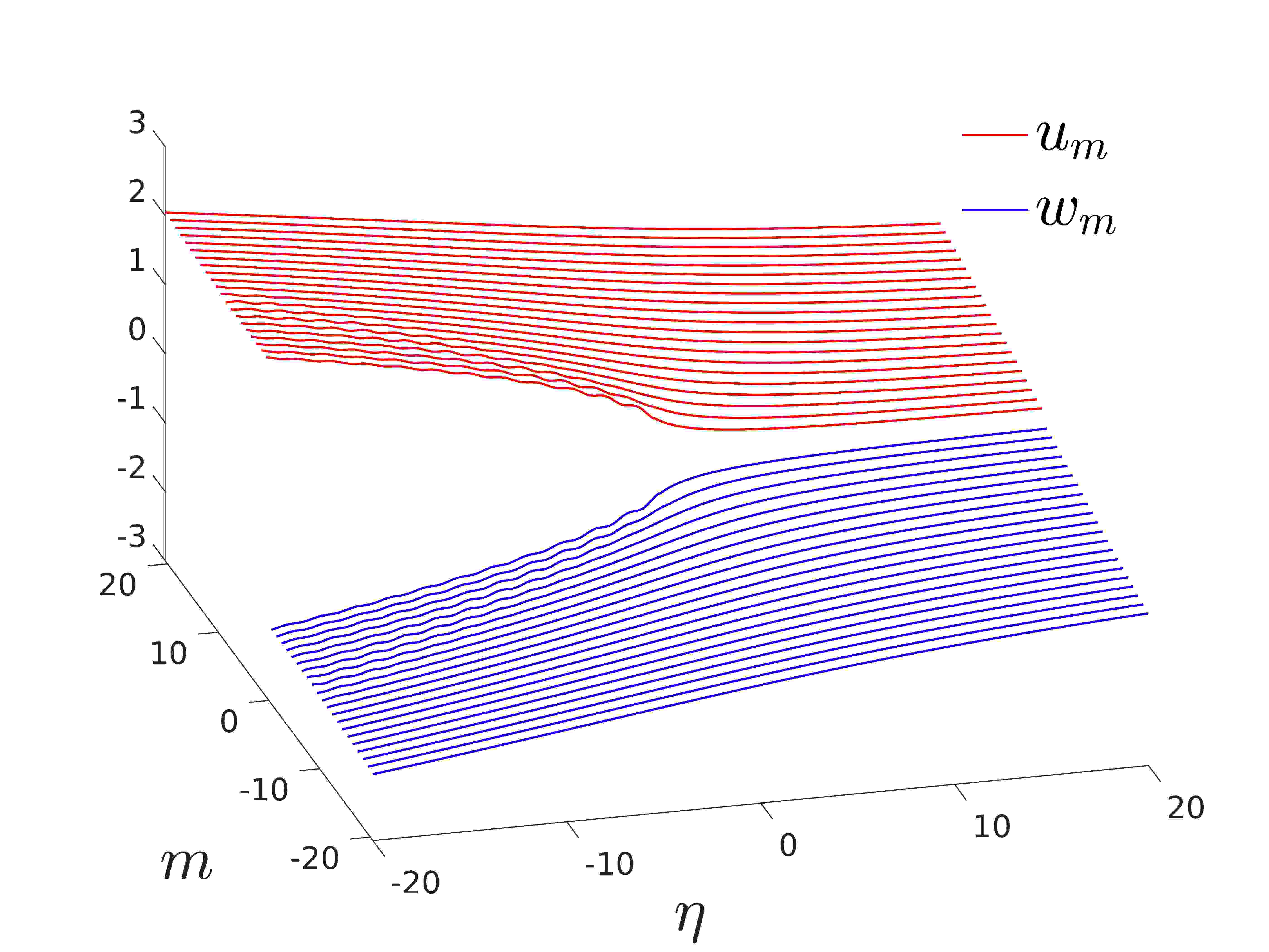
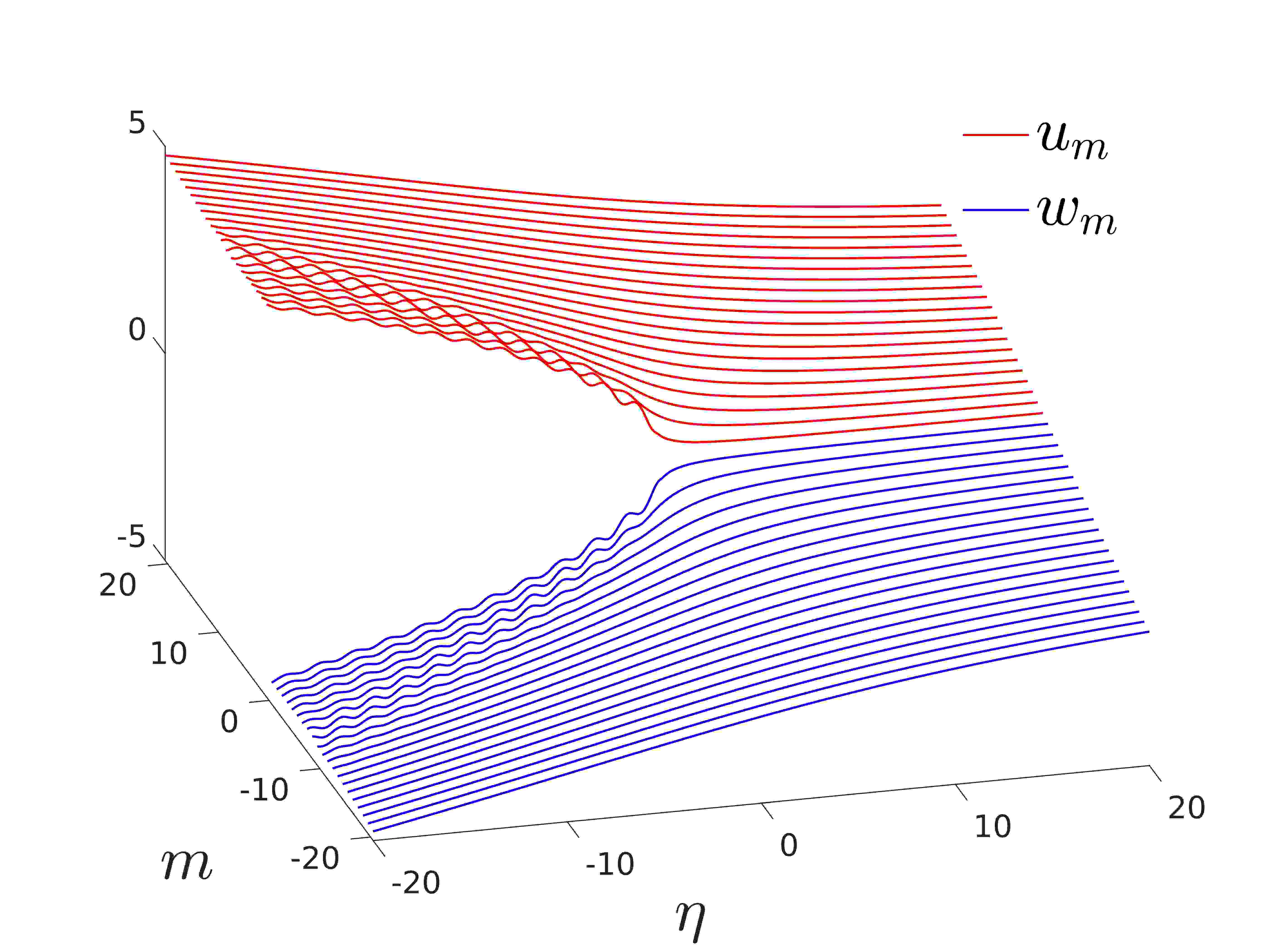
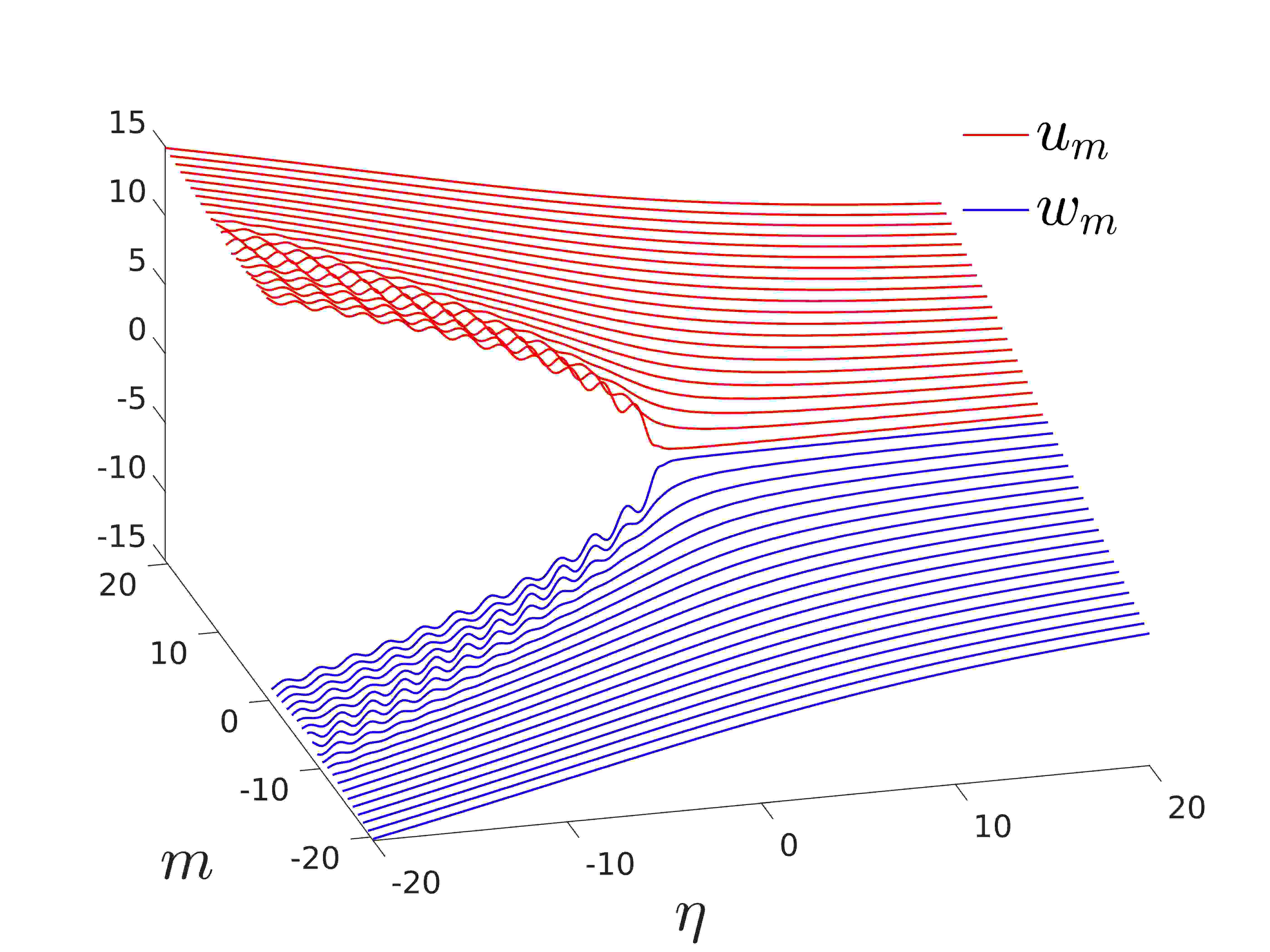
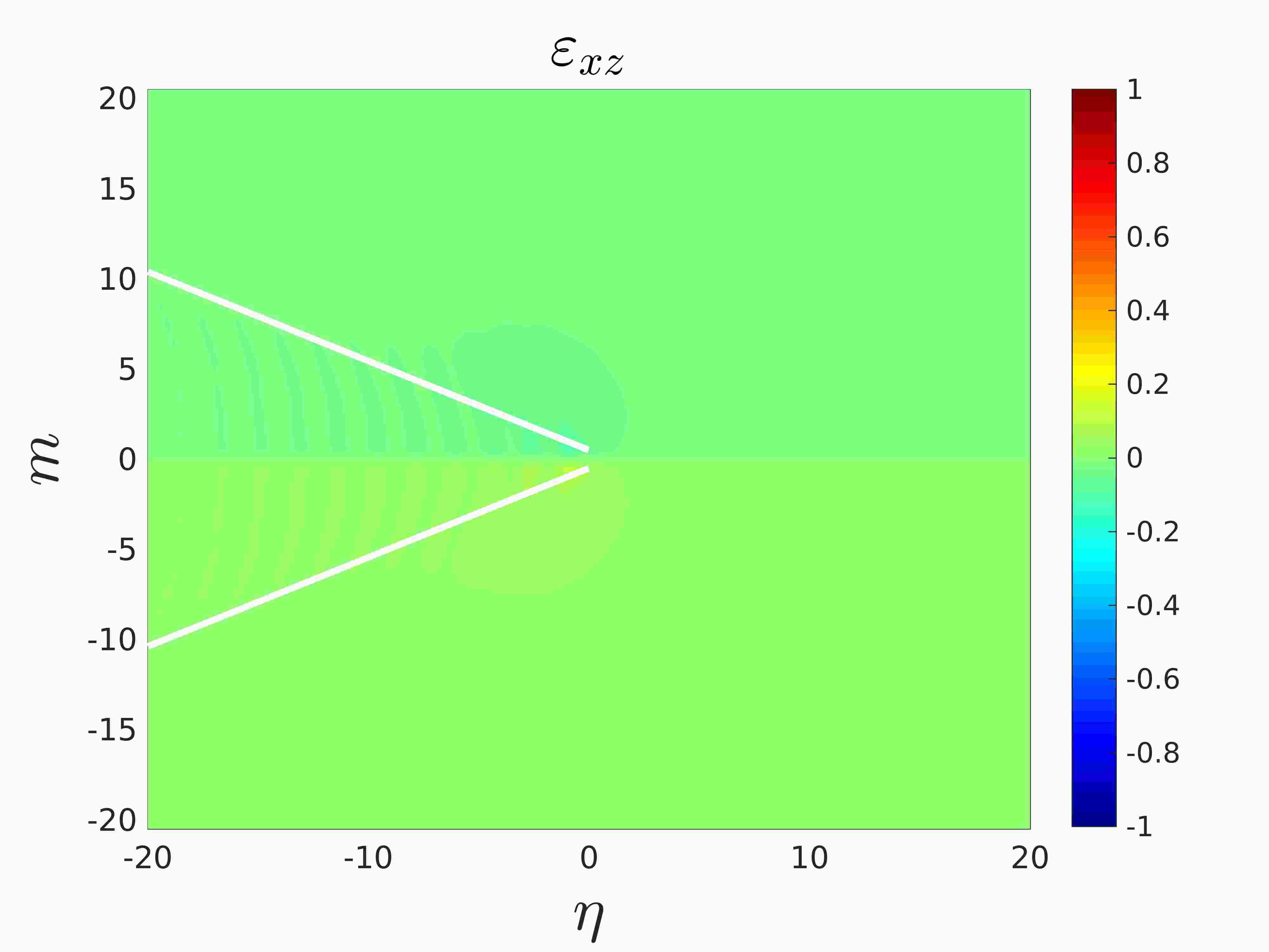
The crosses along each curve in Figure 7 also correspond to admissible regimes of crack propagation in the lattice and the associated dynamic behaviour of the structure is considered in Figures 8 and 9 for these points. In particular, Figures 8 and 9 provide information about the lattice behaviour at intermediate crack speeds () and at high crack speeds (), respectively.
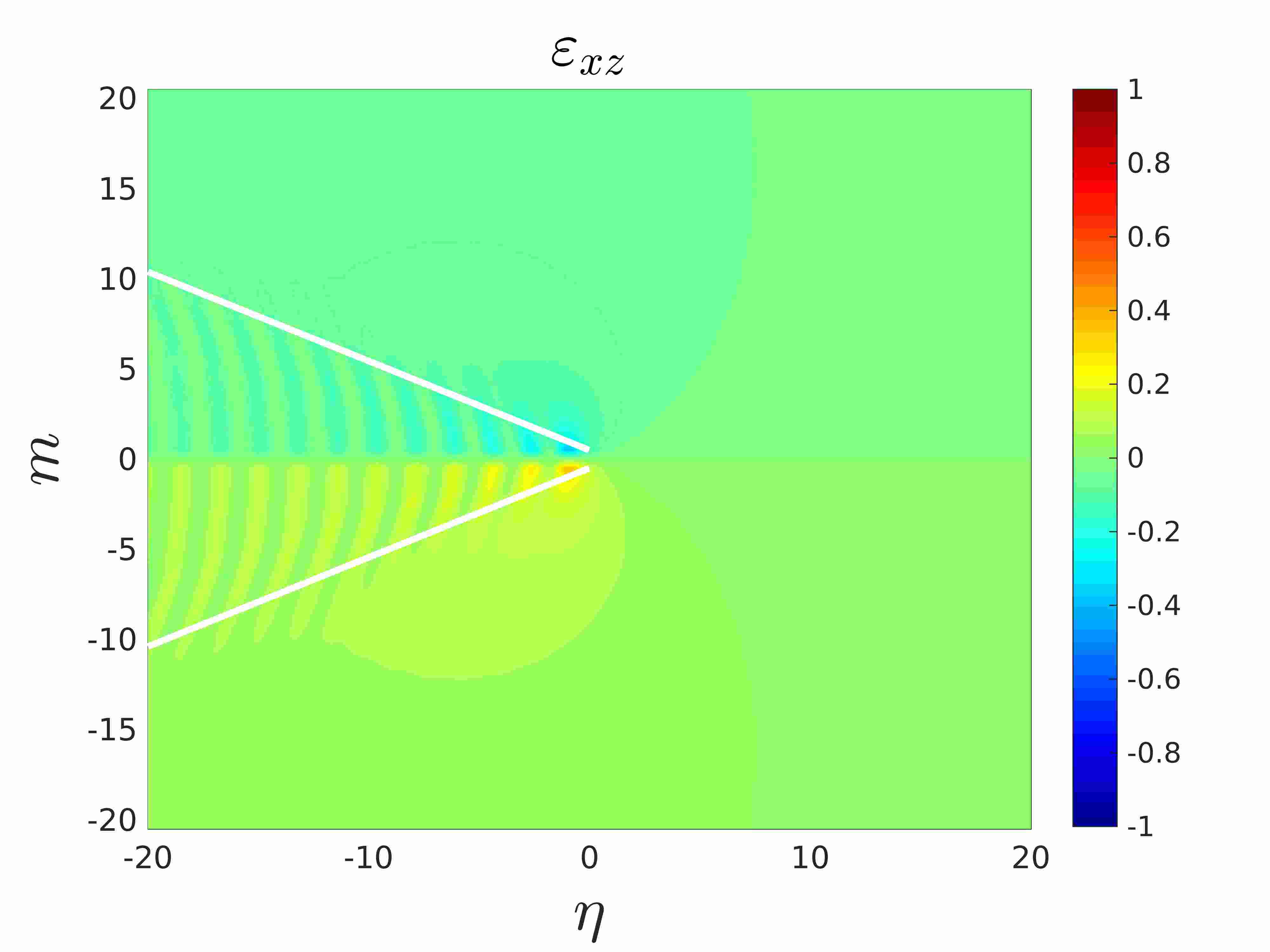
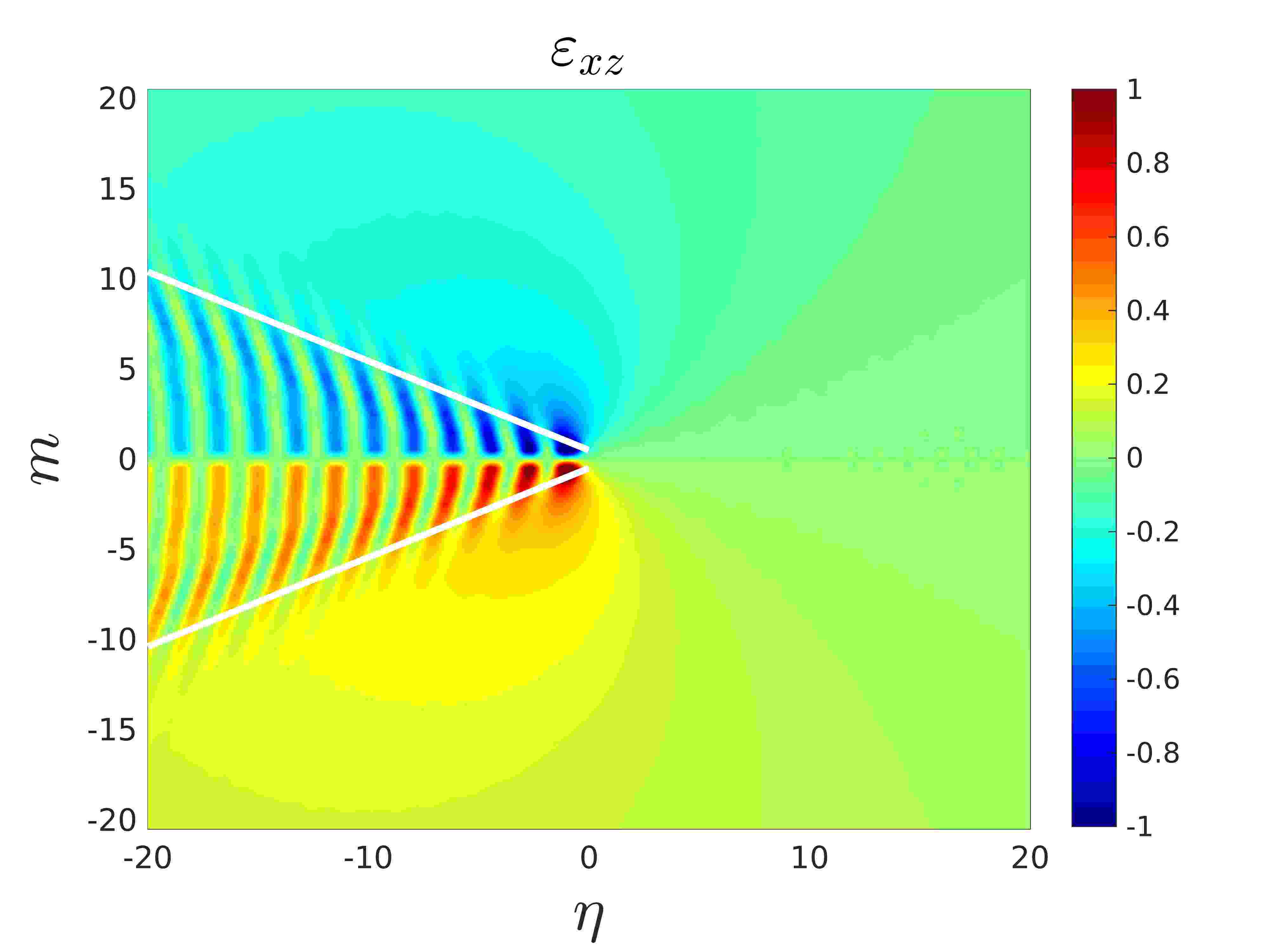
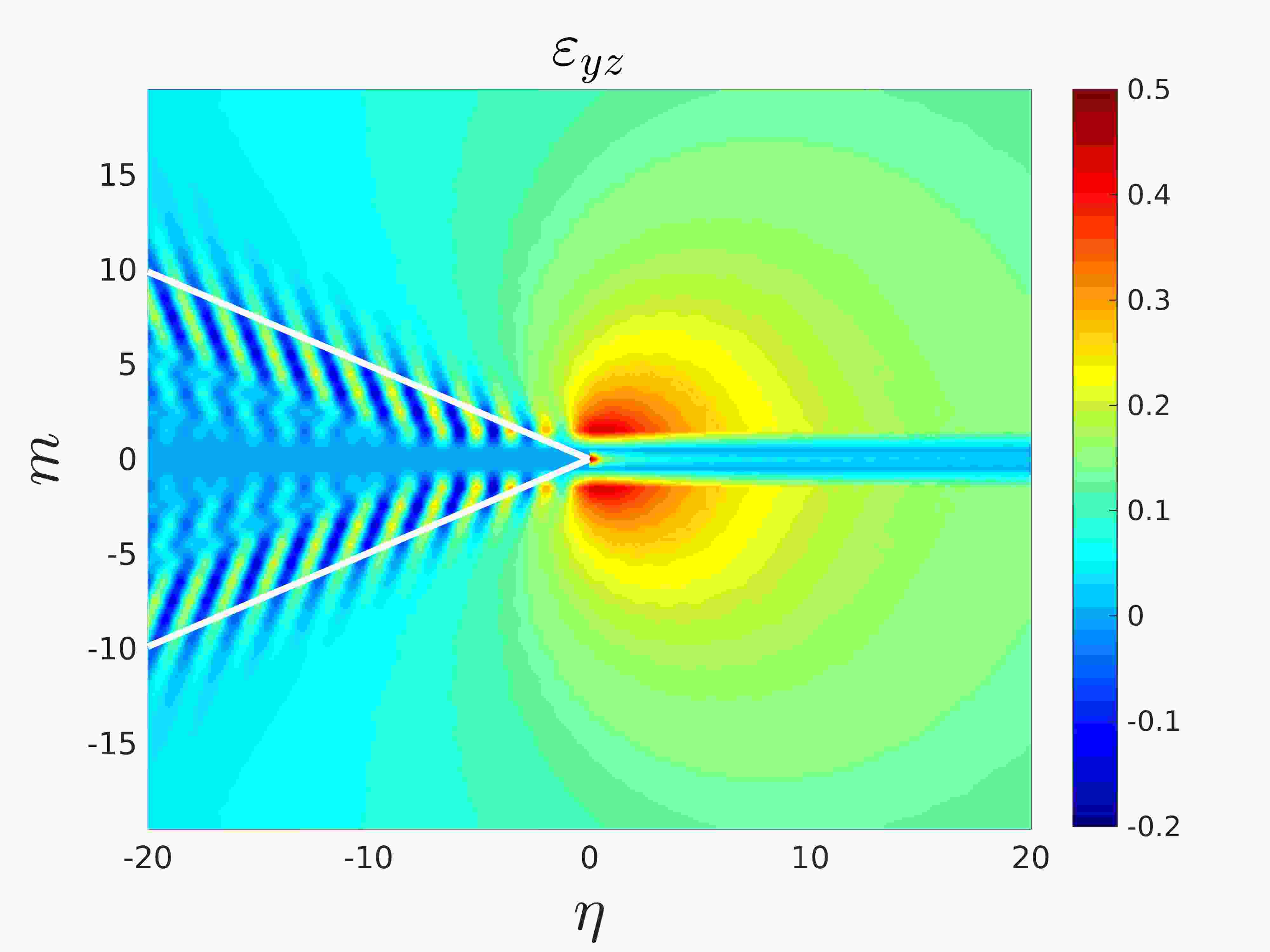
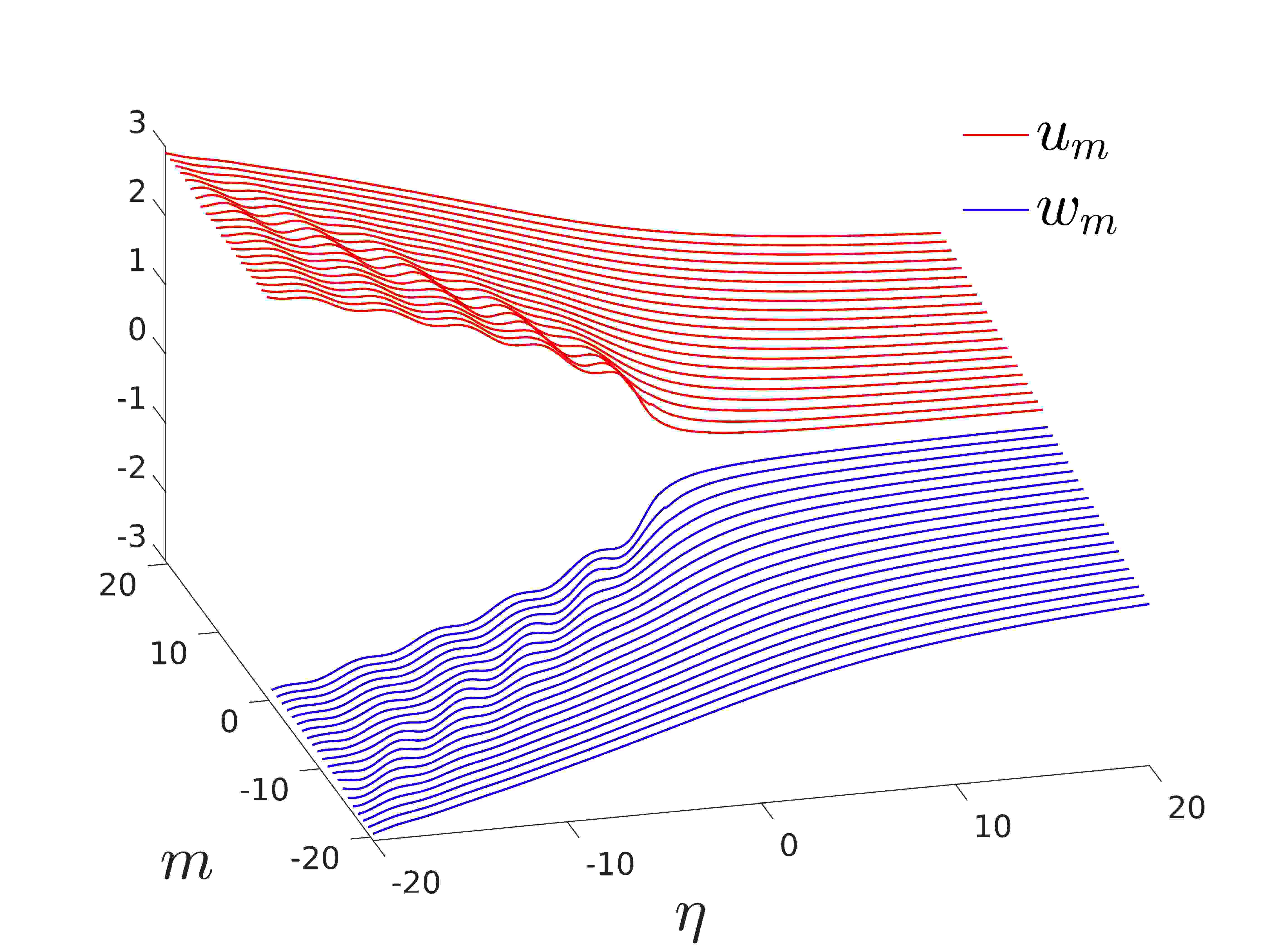
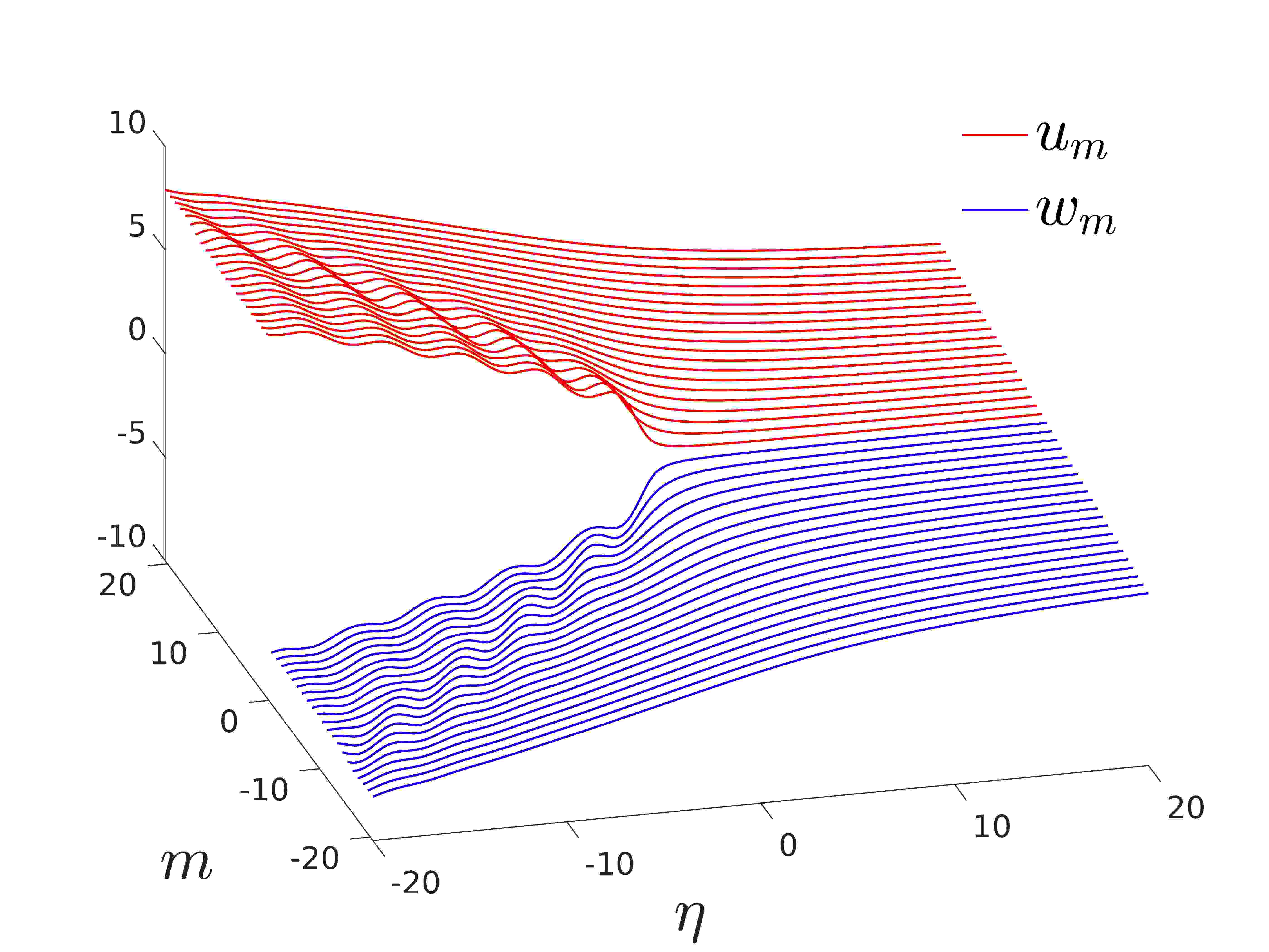
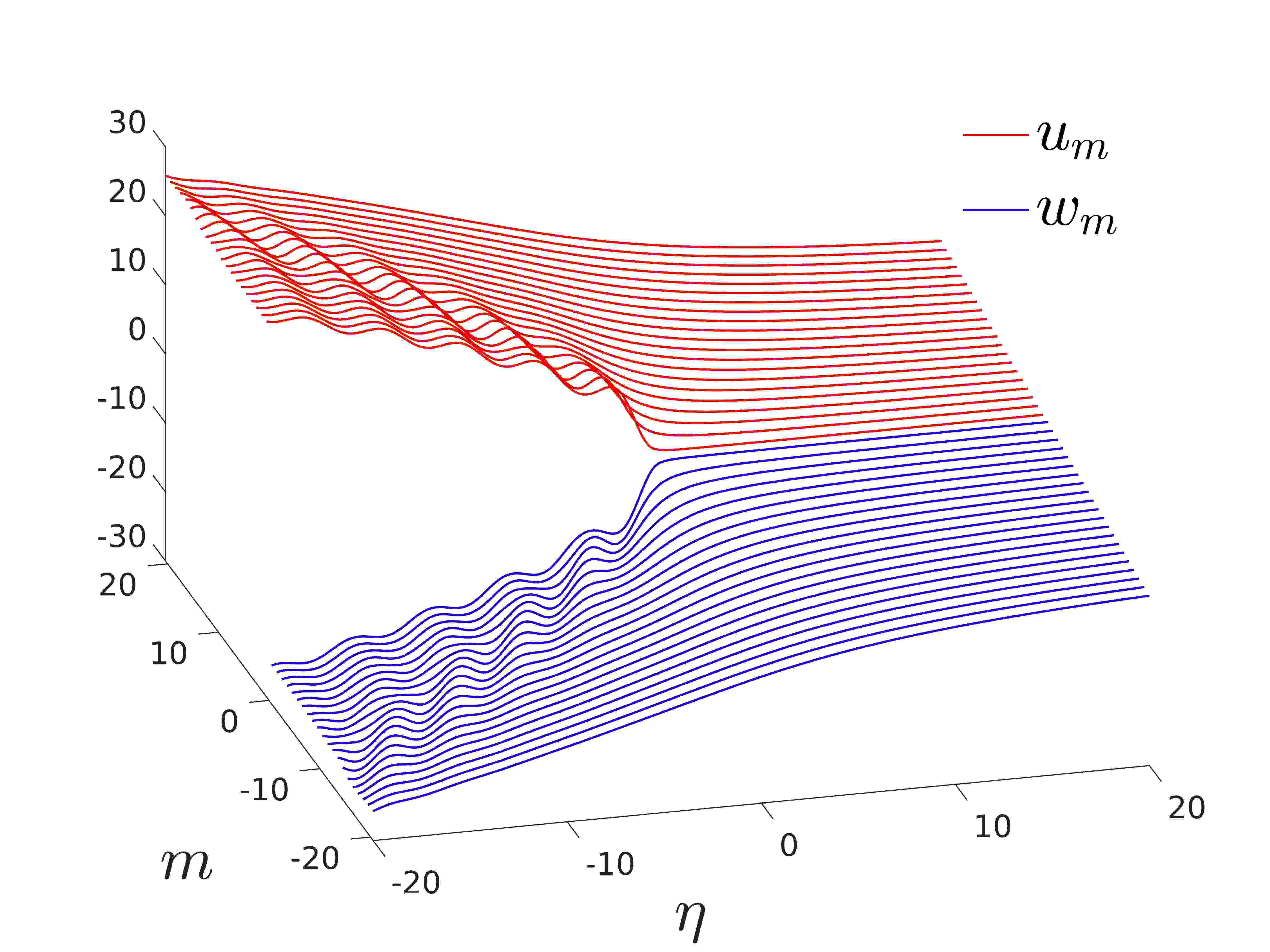
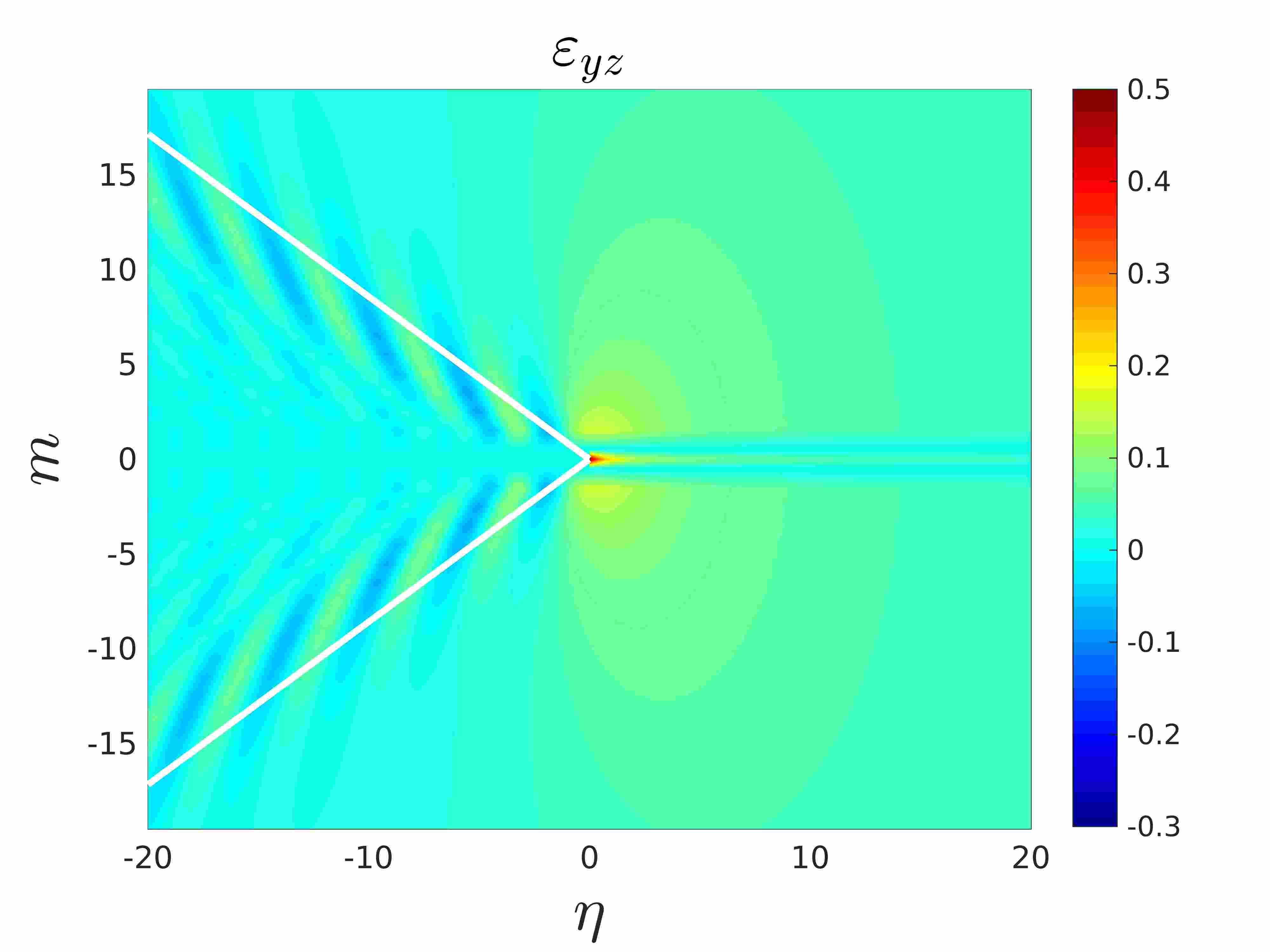
The first row of panels in Figure 8 show the lattice displacements in the vicinity of the crack tip. Since we assume the strength of the interface does not depend on , as we increase the interface stiffness we have to increase the crack opening. These figures also demonstrate that softer interfaces lead to a decrease in the amount of energy radiated by the crack tip as it propagates. This is further supported by Figure 7, where for takes its largest values from the cases presented. Consequently, the deformations behind crack tip for softer interfaces are less pronounced, as evidenced when comparing Figure 8(a) with (c).
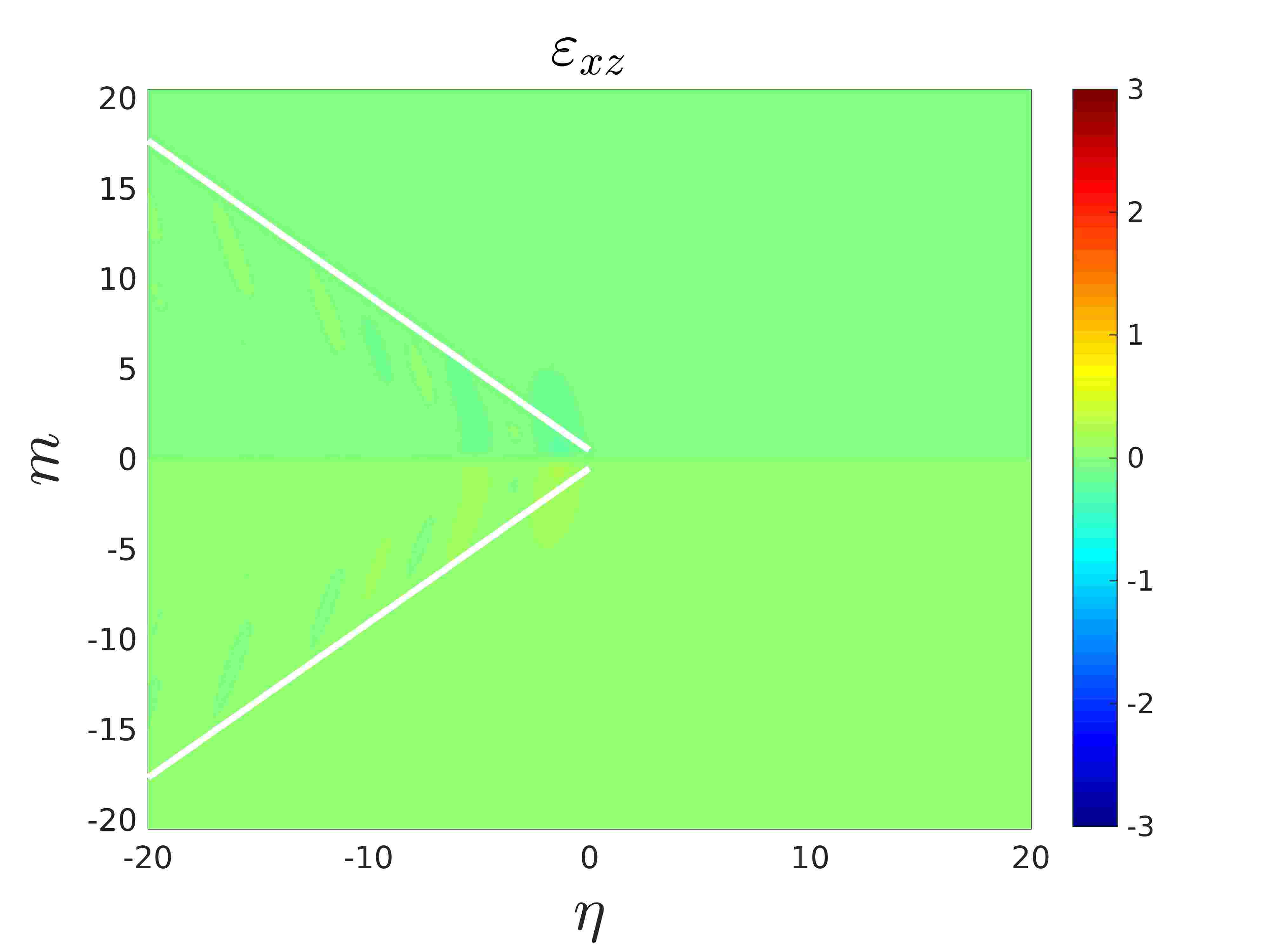
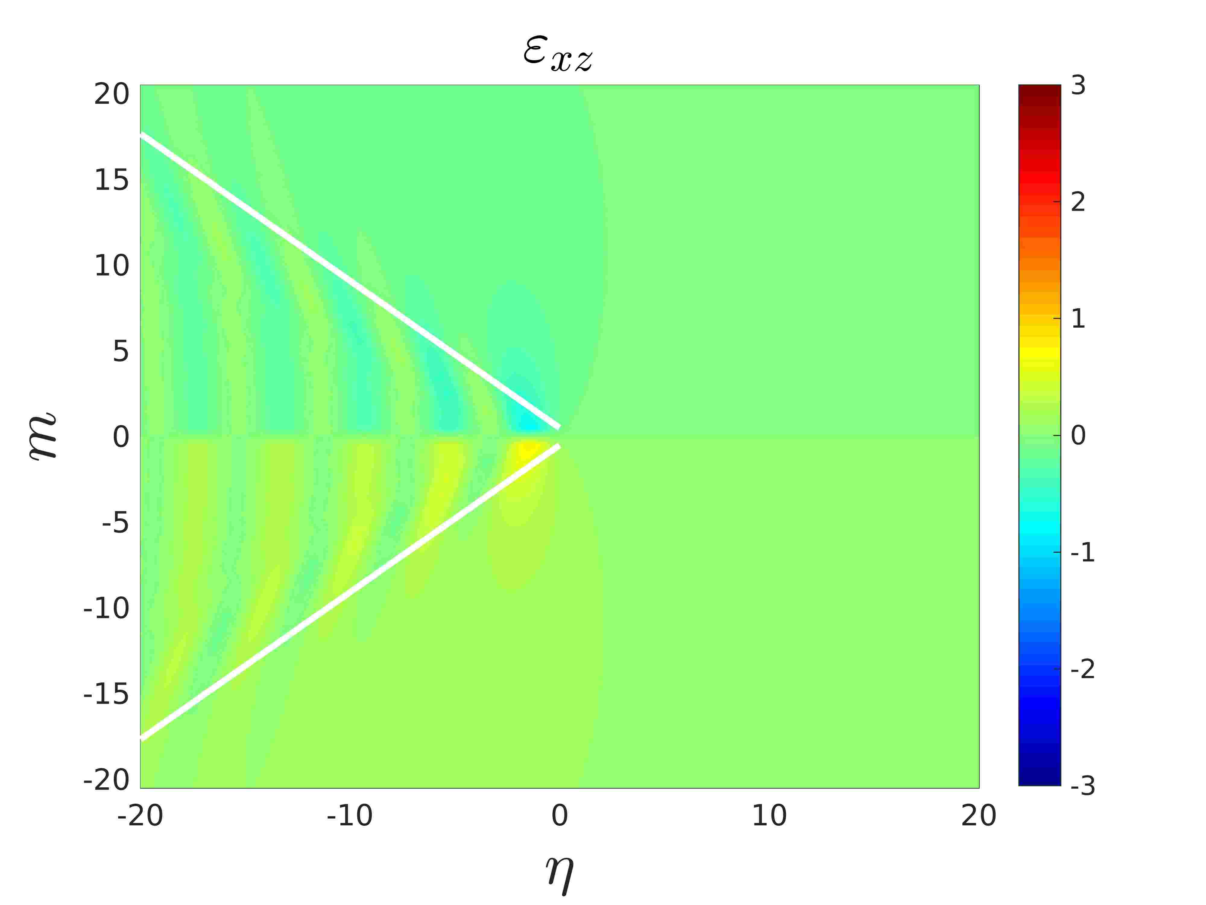
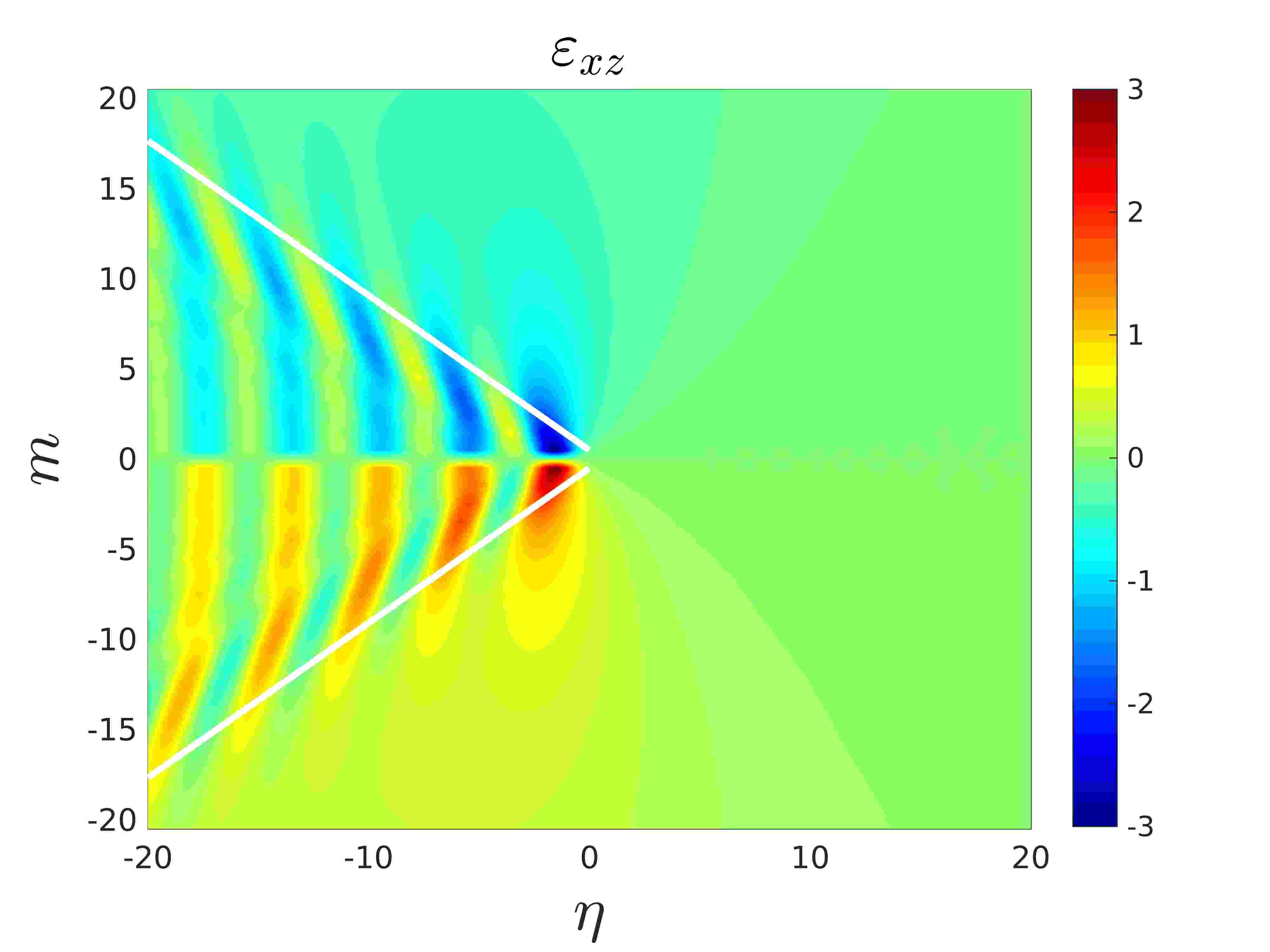
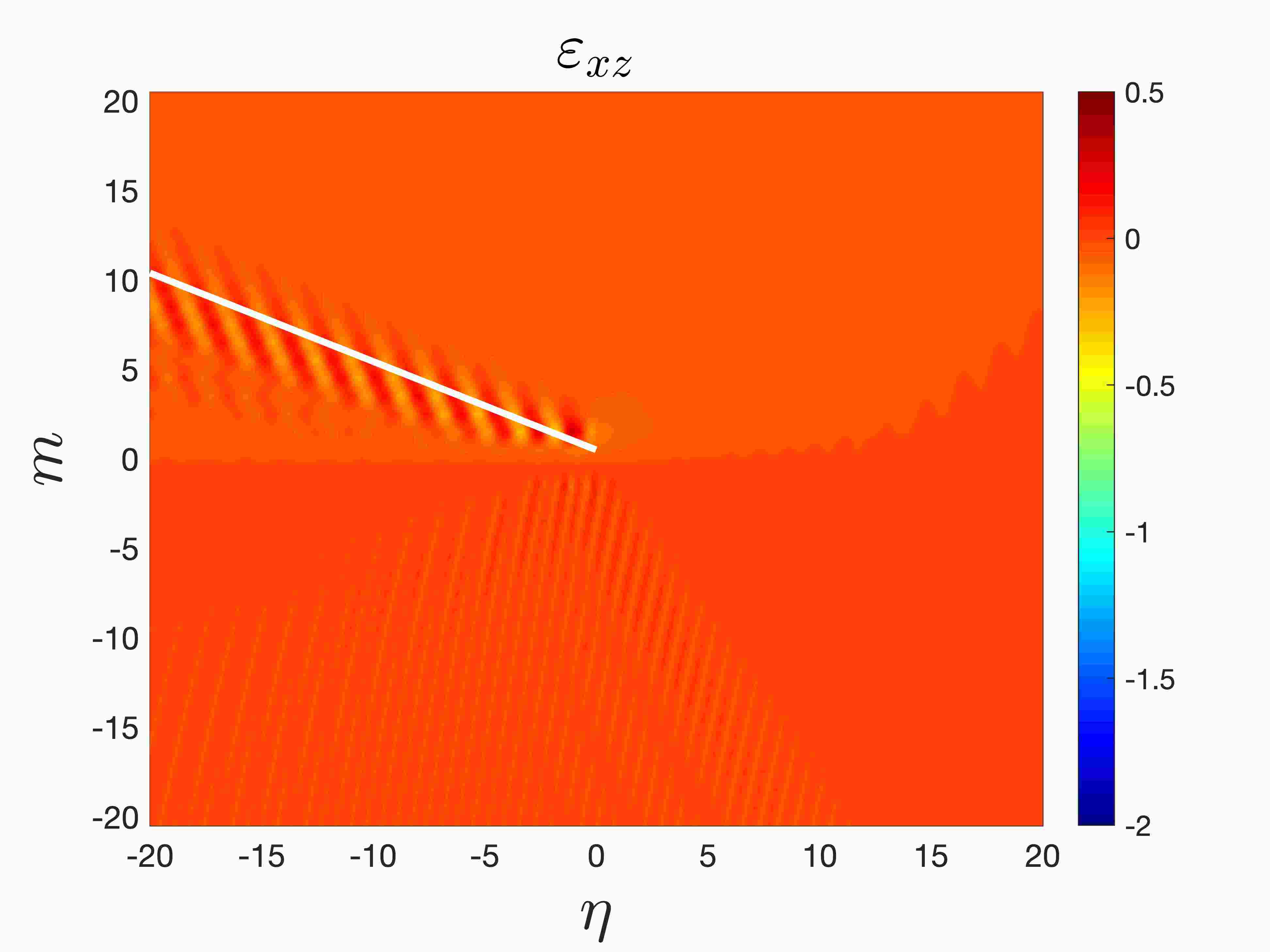
The second row of panels in Figure 8 show the strains based on (81) and (82). They give an indication of the behaviour of the lattice behind the crack tip. Located there are several ripples in the strains that are confined within the region defined by the wave radiation rays, represented by white lines in Figures 8(d)–(i). Note, as shown in Section 4.2 and the Supplementary Material SM.6, the wave radiation rays are independent of the interfacial bond stiffness , as they are linked to the rate of decay of the field in the ambient lattices that is governed by , . As a result of the structural symmetry about the crack line, these radiation rays are also symmetric about this line. Increasing causes an increase in the intensity of the deformations along the ripples in Figures 8(d)–(f) in the displacements behind the crack tip (compare Figure 8(d) with (f)). As we will show later, higher speeds will decrease the number of ripples behind the crack tip (e.g. see Figure 9). In particular, in all examples shown here, the strains in the lattice are small for soft interfaces.
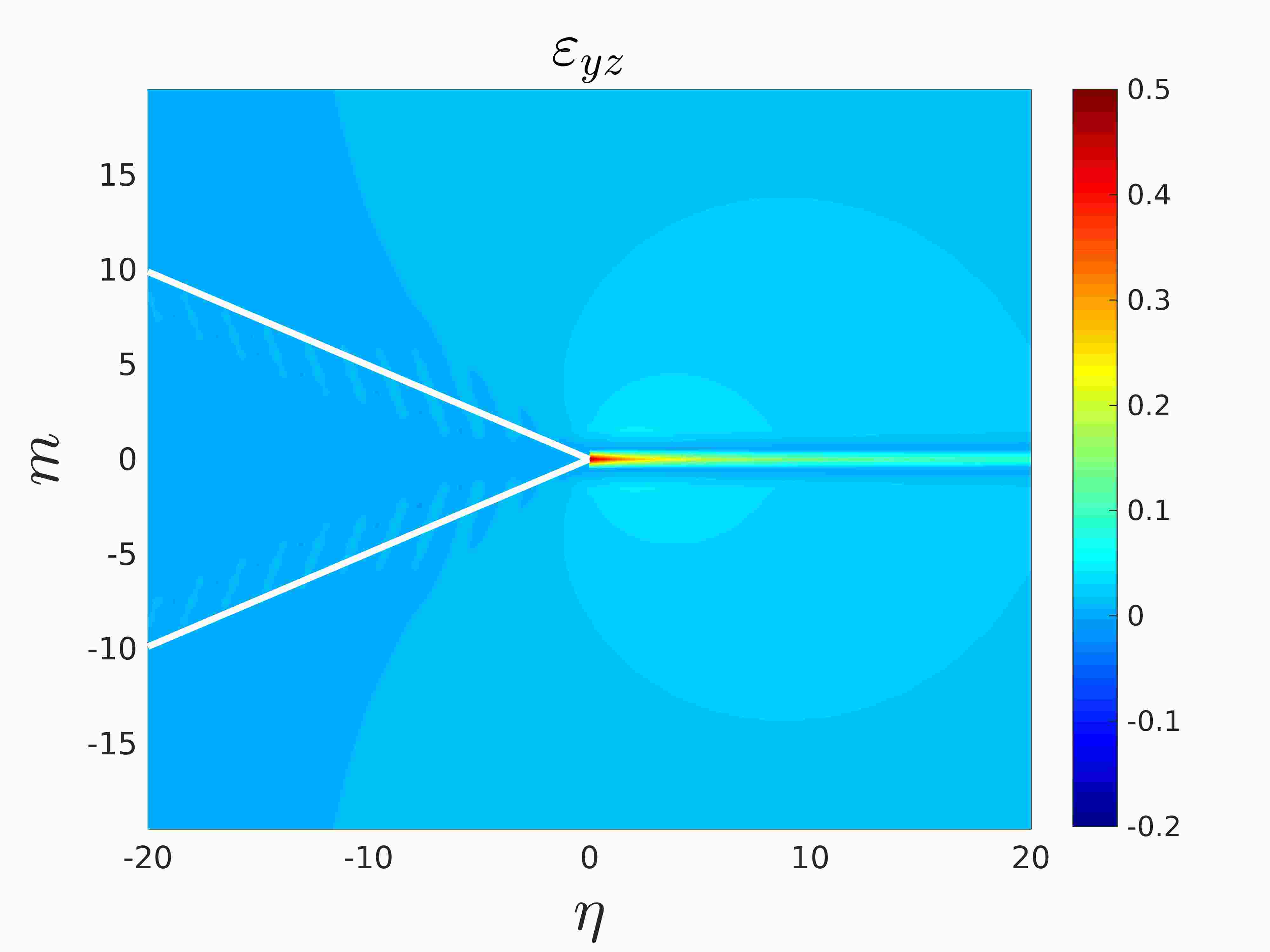
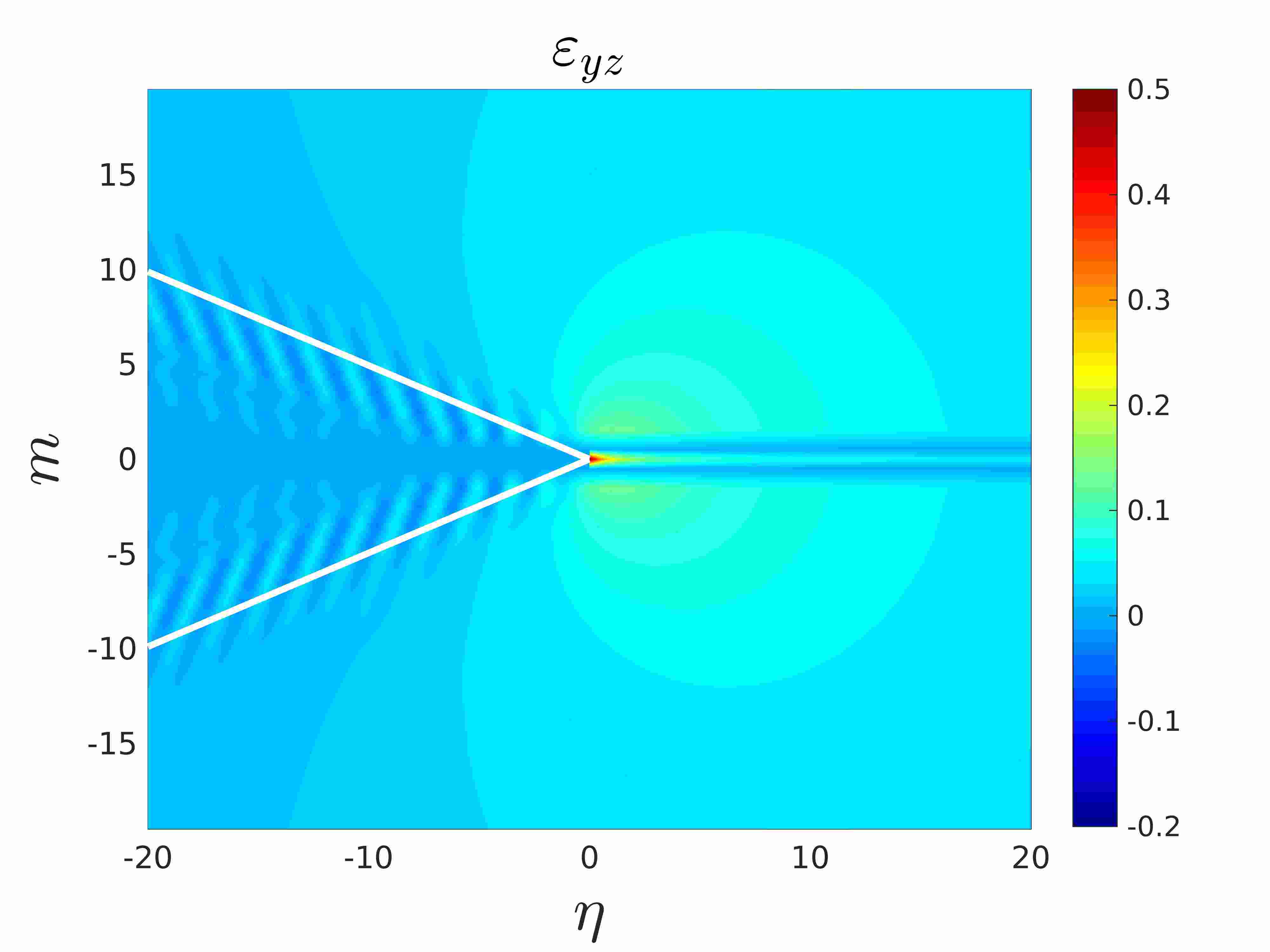
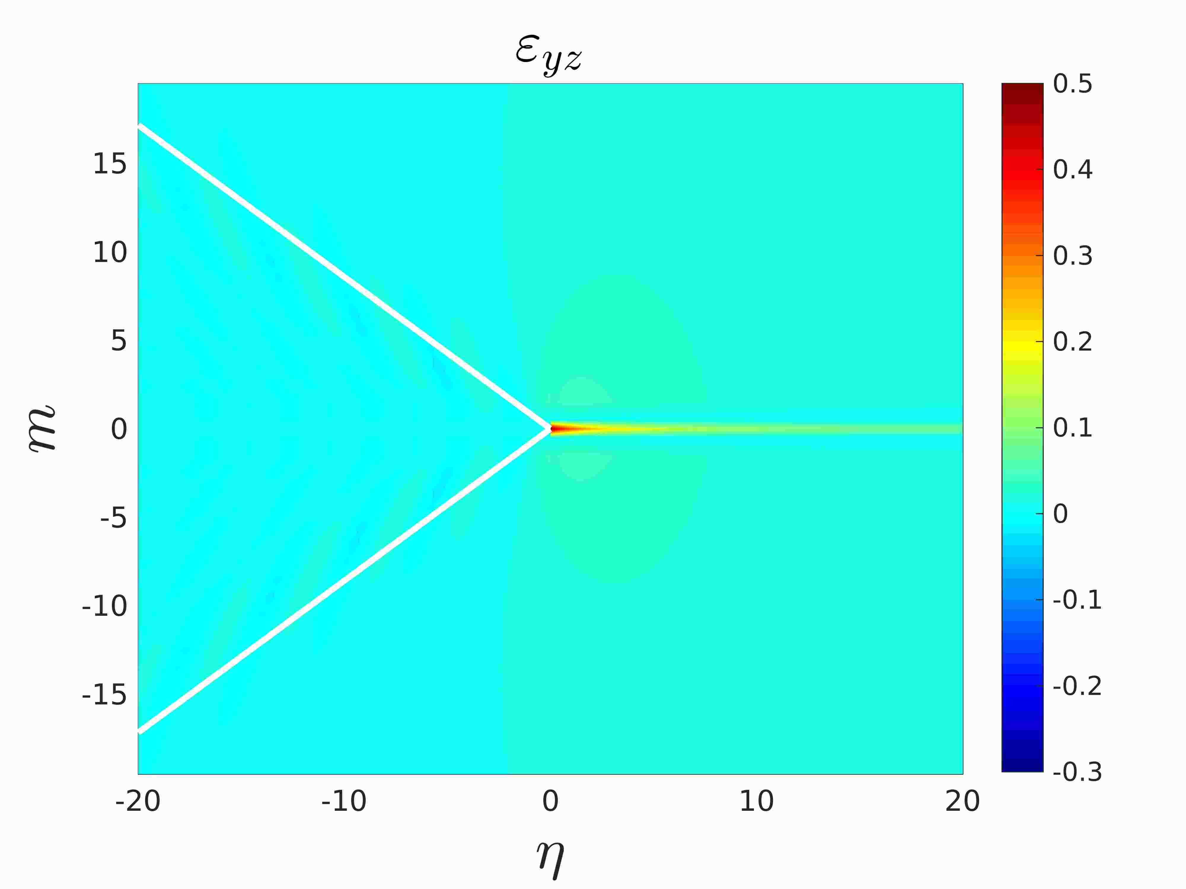
The third row of Figure 8 illustrates the behaviour of the strains based on (83). They show the strains are symmetric with respect to the crack line. Naturally, the strain concentration is near the crack tip. For lattices with soft interfaces, the most prominent strains are found in the vicinity and ahead of the crack tip (see Figure 8(g)). The bulk lattice strains are usually smaller in comparison, again confirming that propagating cracks within soft interfaces are less likely to promote the radiation of lattice vibrations.
In addition, Figures 8(h) and (i) show the emergence of a region of localised deformation in the vicinity of the crack tip. The intensity of the deformation there increases as the interface stiffness becomes larger for a fixed speed. It is clear that larger causes this deformation to be comparable with that at the crack tip. This effect could potentially lead to a solution of the problem which is not admissible for this given speed, as discussed above. The strains shown in Figures 8(h) and (i) also illustrate clearly the preferential directions for the lattice wave radiation, along which the vibration amplitude decays the slowest, and these directions coincide with the wave radiation segments predicted by (79). Further, the intensity of the waves along the radiation rays increase if the stiffness of the interface is also increased.
We note that Figure 8 shows the displacement field has a square root type growth like , , far away from the crack tip, but both strains tend to zero in the far-field of the lattice as for evident reasons. This behaviour in the remote regions of the lattice is consistent with the field in the vicinity of a crack tip propagating within the continuous bimaterial. On the other hand, along the wave radiation rays in the lattice, as discussed in Section 4.2 and the Supplementary Material, the wave amplitudes decay like .
(a)
 (b)
(b)
 (c)
(c)
(d)
 (e)
(e)
 (f)
(f)
(g)
 (h)
(h)
 (i)
(i)
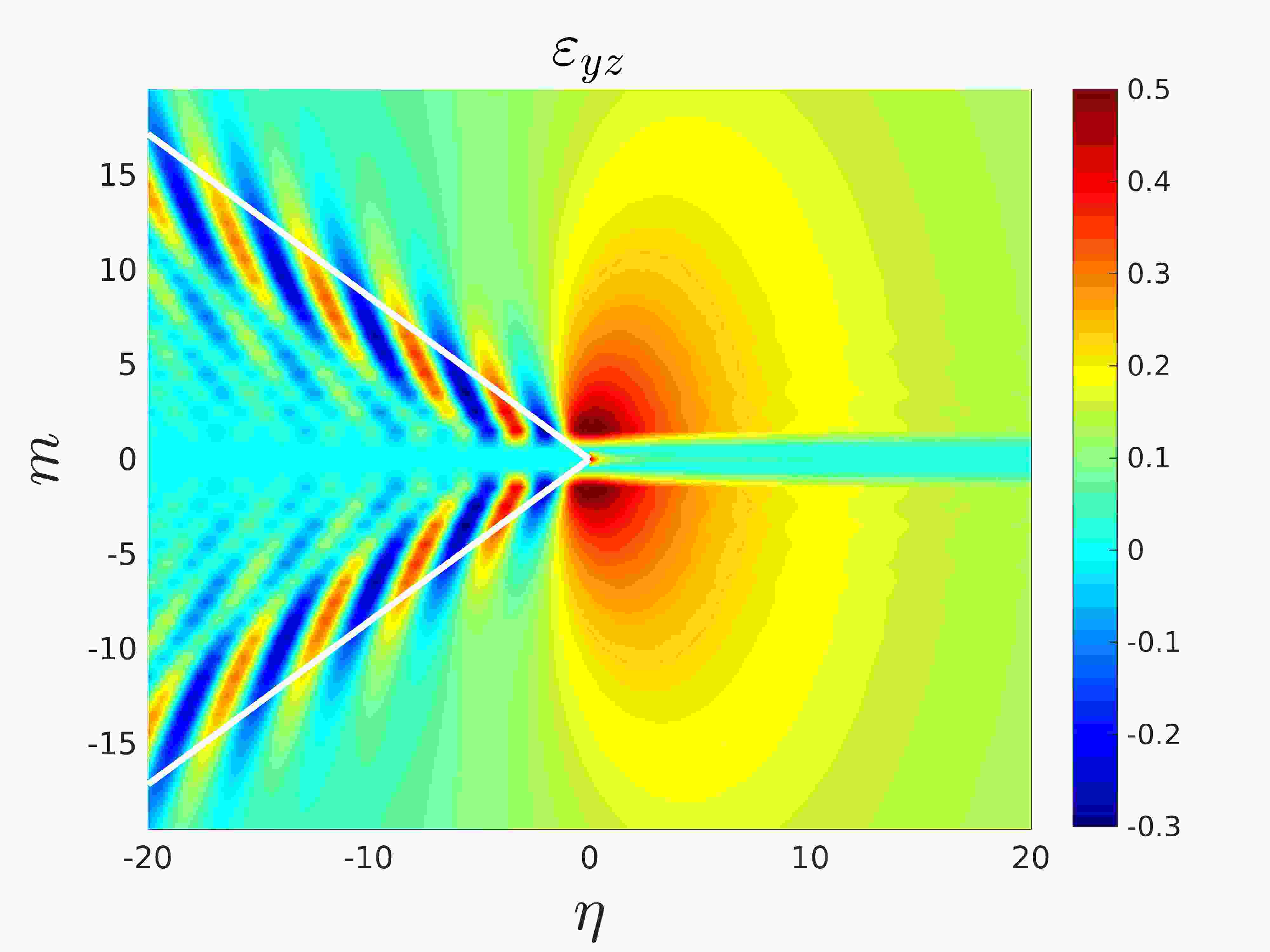
Next, we discuss the effect of increasing the fracture speed . Figure 9 shows the behaviour of the lattice with an interfacial crack for the case of . For a given , comparing the top rows of Figures 8 and 9, it is clear that increase of the failure speed leads to an increase in the crack opening (e.g. see Figure 8(a) with Figure 9(a)). In addition, the oscillations in the wake of the tip of the faster crack are now more pronounced and have a longer wavelength than those observed in Figure 8. These effects are localised to the region defined by the wave radiation rays shown in the second and third rows of Figure 9, corresponding to the results for the strain fields and , respectively, obtained using (81), (82) and (83). Note these strain fields indicate that the deformations behind the crack tip are now less localised about the crack line in comparison with the results of Figure 8.
The increase in the crack speed has also led to an increase in the area bounded by the radiation rays, within which a highly oscillatory behaviour of the lattice displacements can occur. In particular, comparing Figures 8(h) and (i) with Figures 9(h) and (i), we see that for high interfacial bond stiffness the vibrations distributed along the radiation rays have a greater intensity in the case of . It is also apparent that the likelihood of a crack path instability or roughening of the crack faces is larger for high interfacial bond stiffness and crack speeds. This is evidenced by the fact that there exists a substantial region local to the crack tip in Figure 9(i), where the the lattice deformations are very large in comparison with those in the ambient lattice.
6.2 Dissimilar lattice system exhibiting the same bulk wave speeds
Now we consider the dissimilar lattice system composed of two isotropic lattices, with the same wave speeds that may be directly connected or connected by an interface. Specifically, we will consider the parameters , and and the interfacial bond stiffnesses and 5. Here, and 5 represent the perfect join of the two lattices (i.e. a perfect interface).

Figure 10 shows the ratio as a function of the normalised crack speed . The same behaviour of the ratio observed in Figure 7 is present also in Figure 10. Note that once again the regions representing admissible crack propagation regimes appear as continuous intervals located beyond a sufficiently high crack speed. In consulting Figures 7 and 10, we see that the joining of two contrasting lattices, in both stiffness and density, reduces the energy distributed to wave radiation processes when a crack propagates between these media. This can be seen by comparing the curves in Figures 7 and 10 for the same .
The crosses along each curve in Figure 10 represent scenarios for crack propagation within the dissimilar structure at two different crack speeds. These cases are further investigated in Figures 11 and 12. There, once more the wave radiation rays are presented and are again symmetric about the crack path, despite the fact there is a clear dissimilarity between the properties of the bulk lattices in each case.
(a)
 (b)
(b)
 (c)
(c)
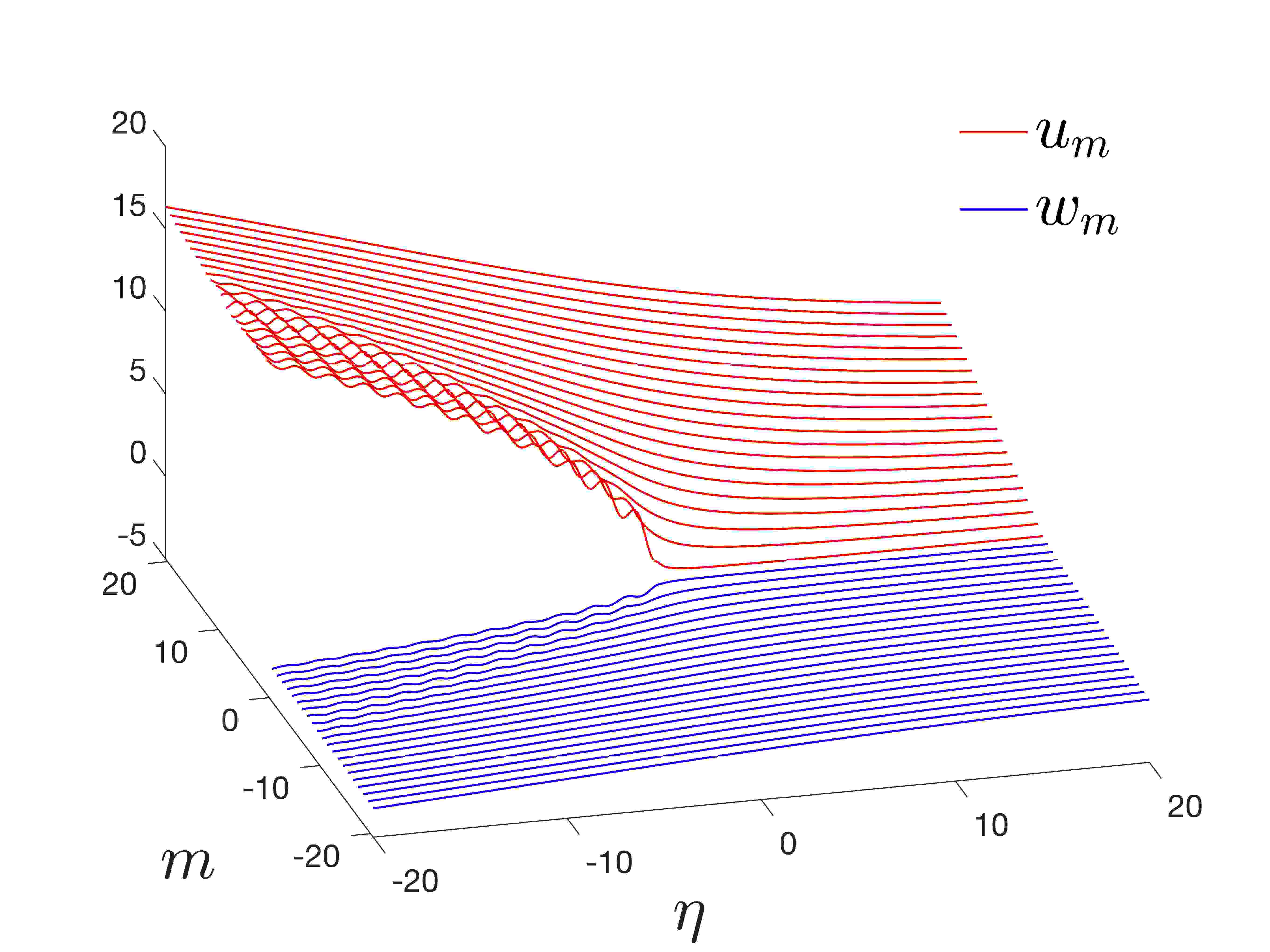
(d)
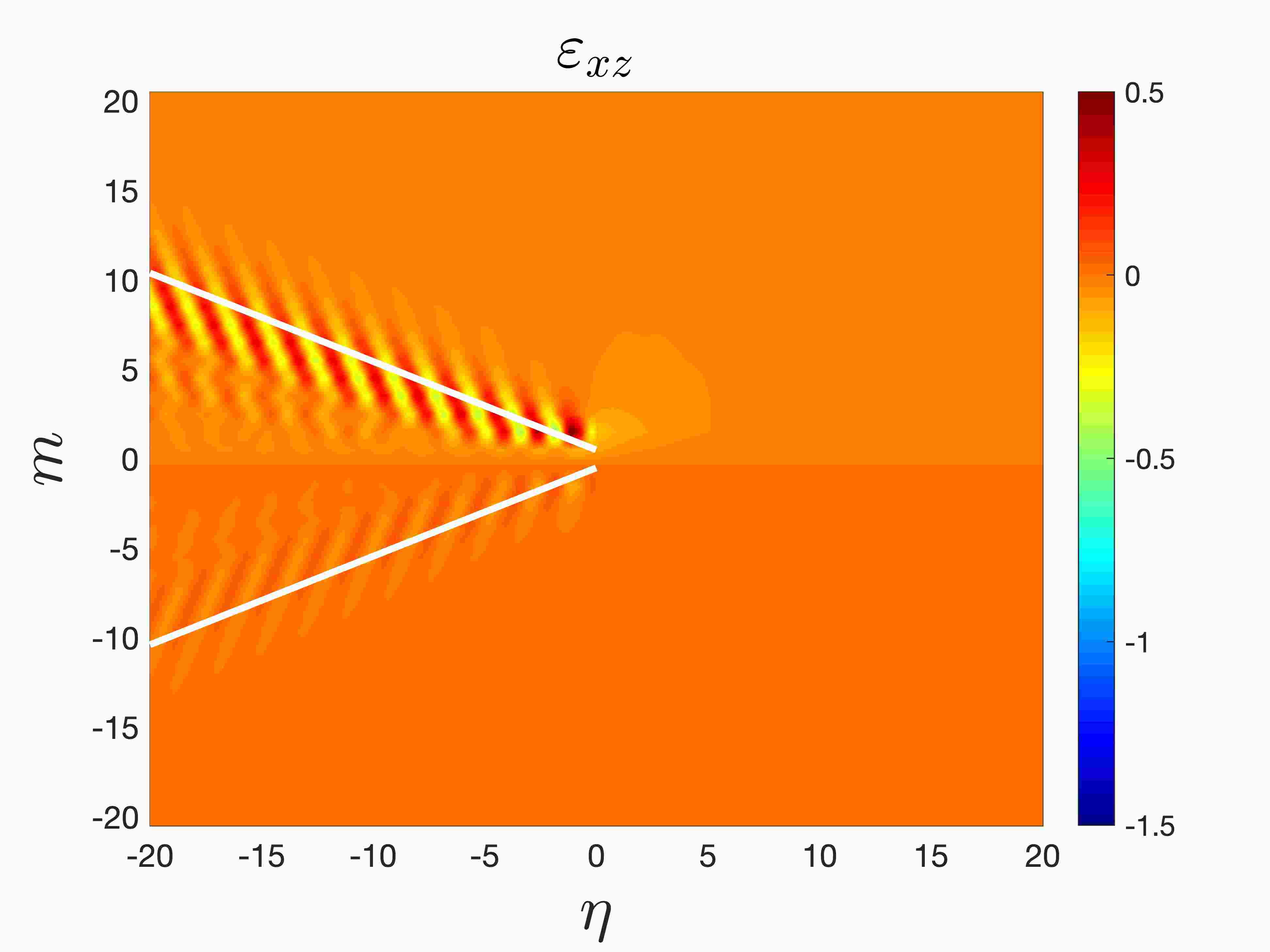 (e)
(e)
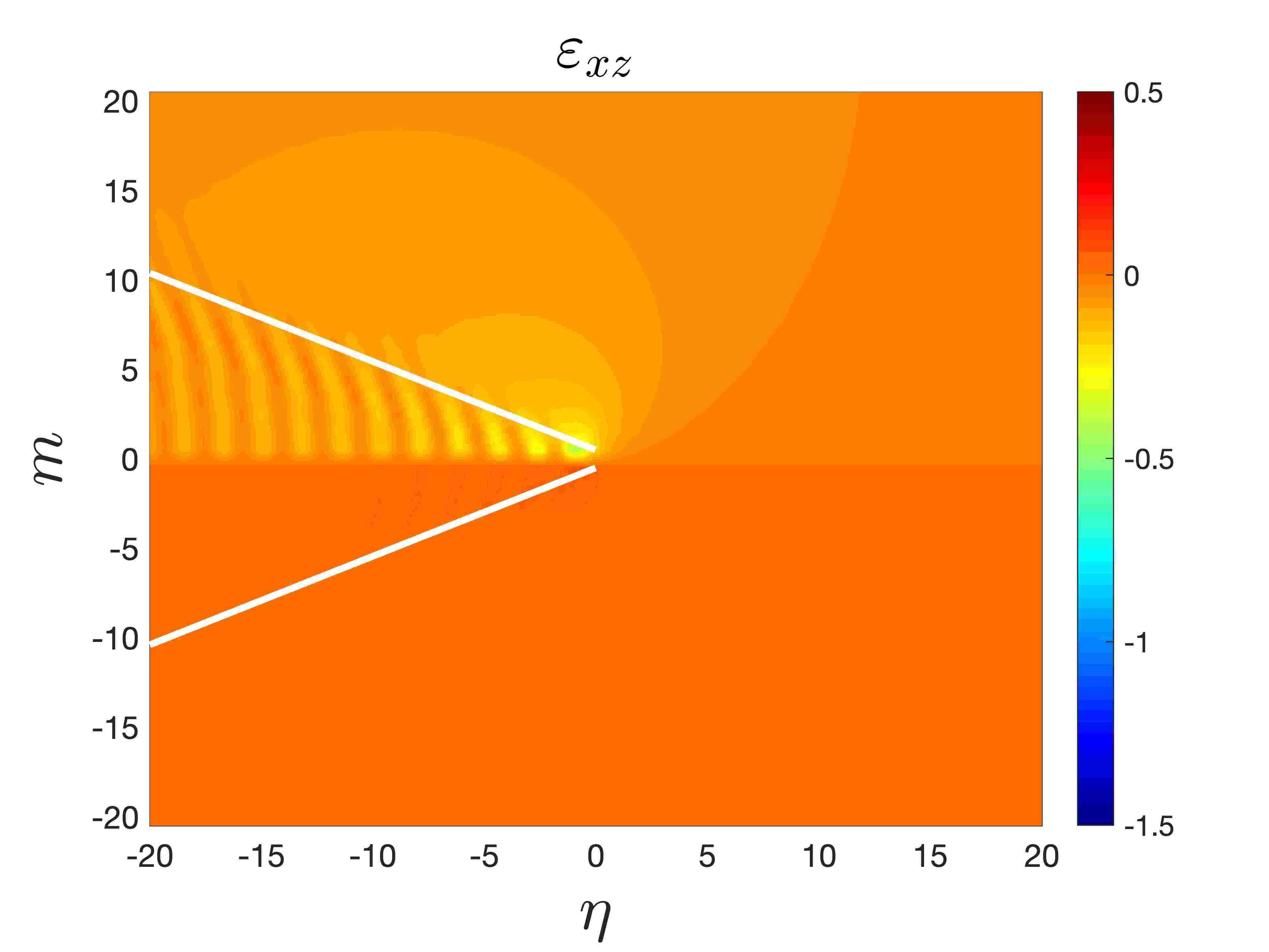 (f)
(f)
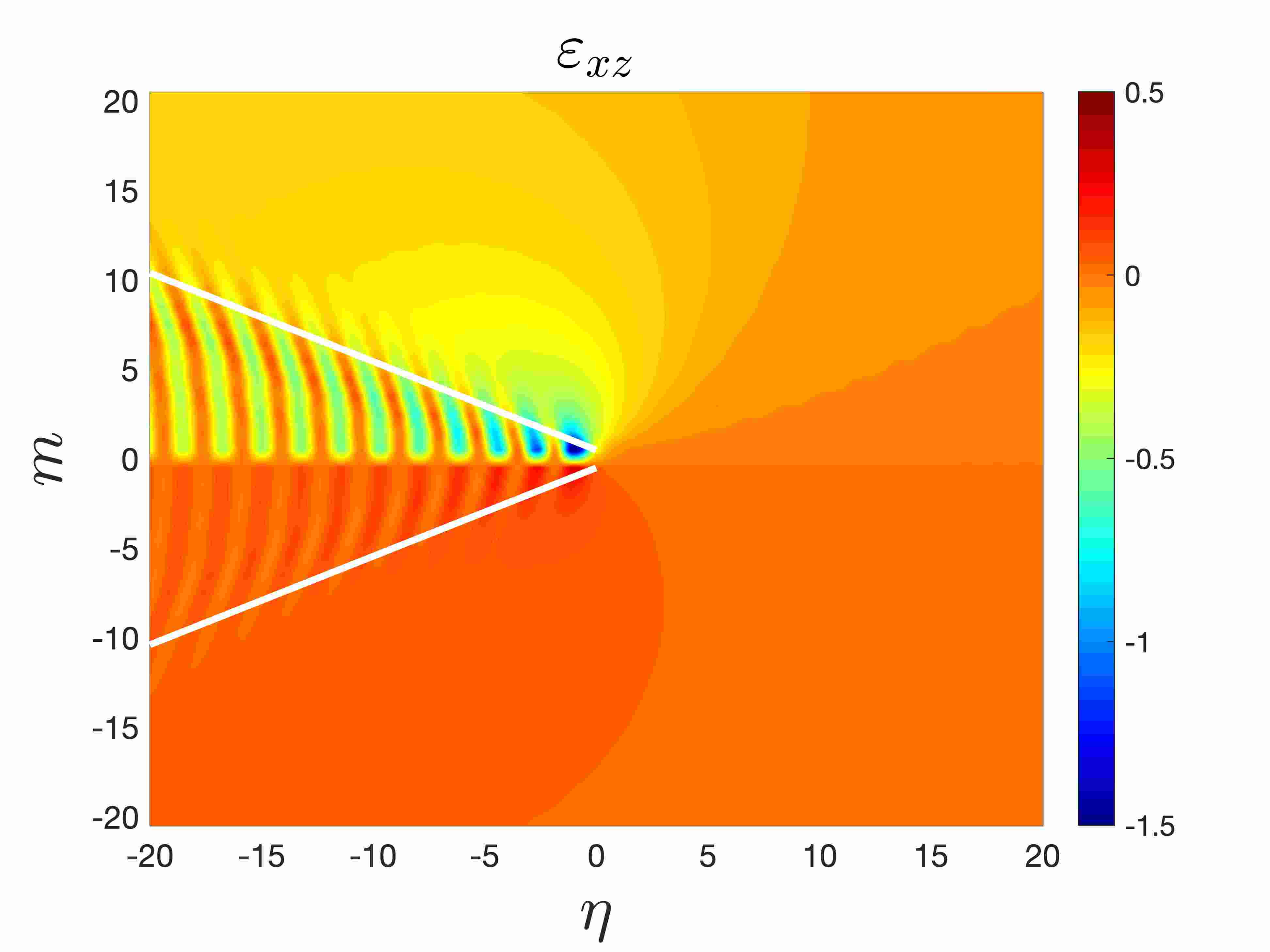
(g)
 (h)
(h)
 (i)
(i)
(a)
 (b)
(b)
 (c)
(c)
(d)
 (e)
(e)
 (f)
(f)
(g)
 (h)
(h)
 (i)
(i)
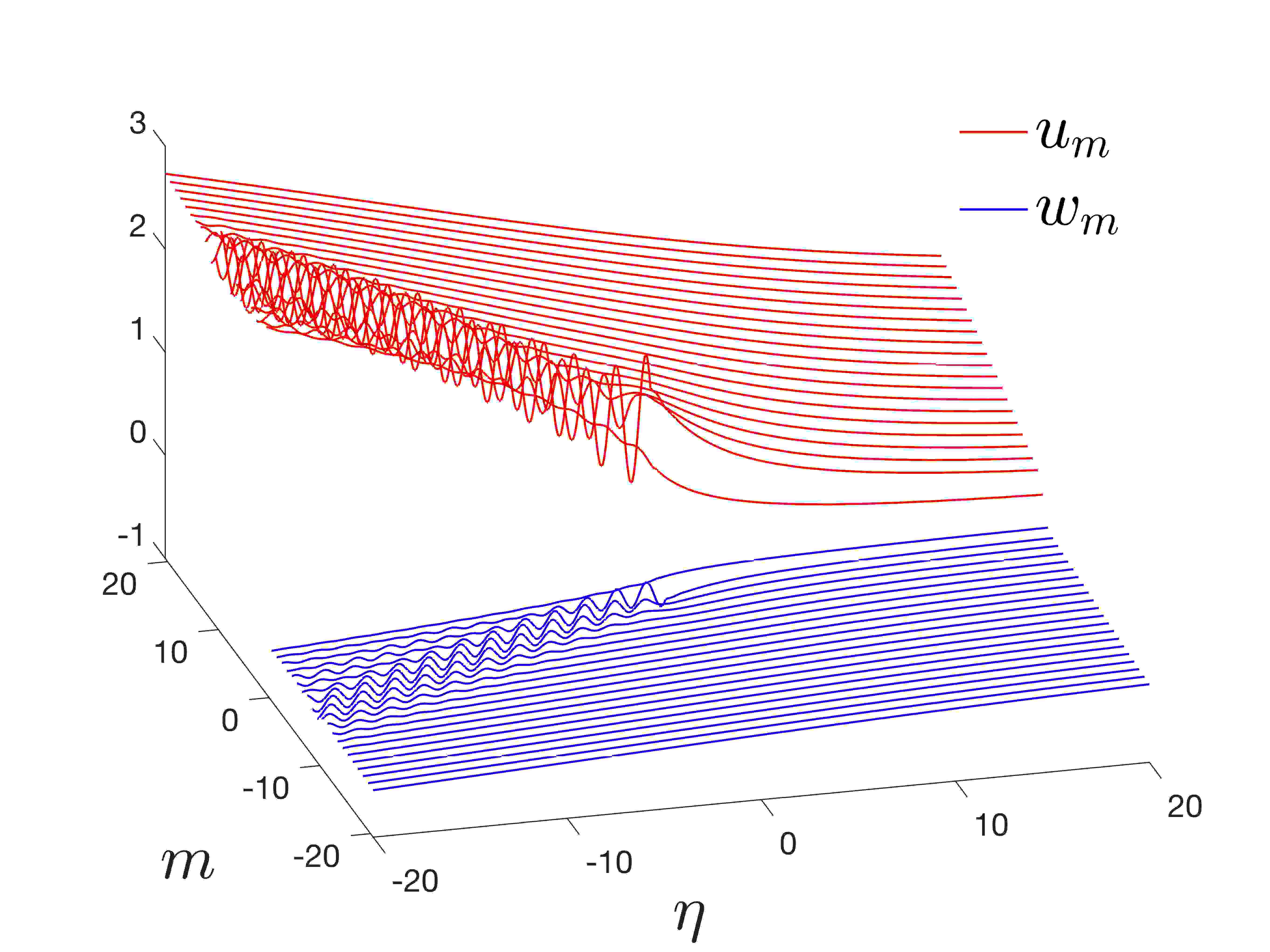
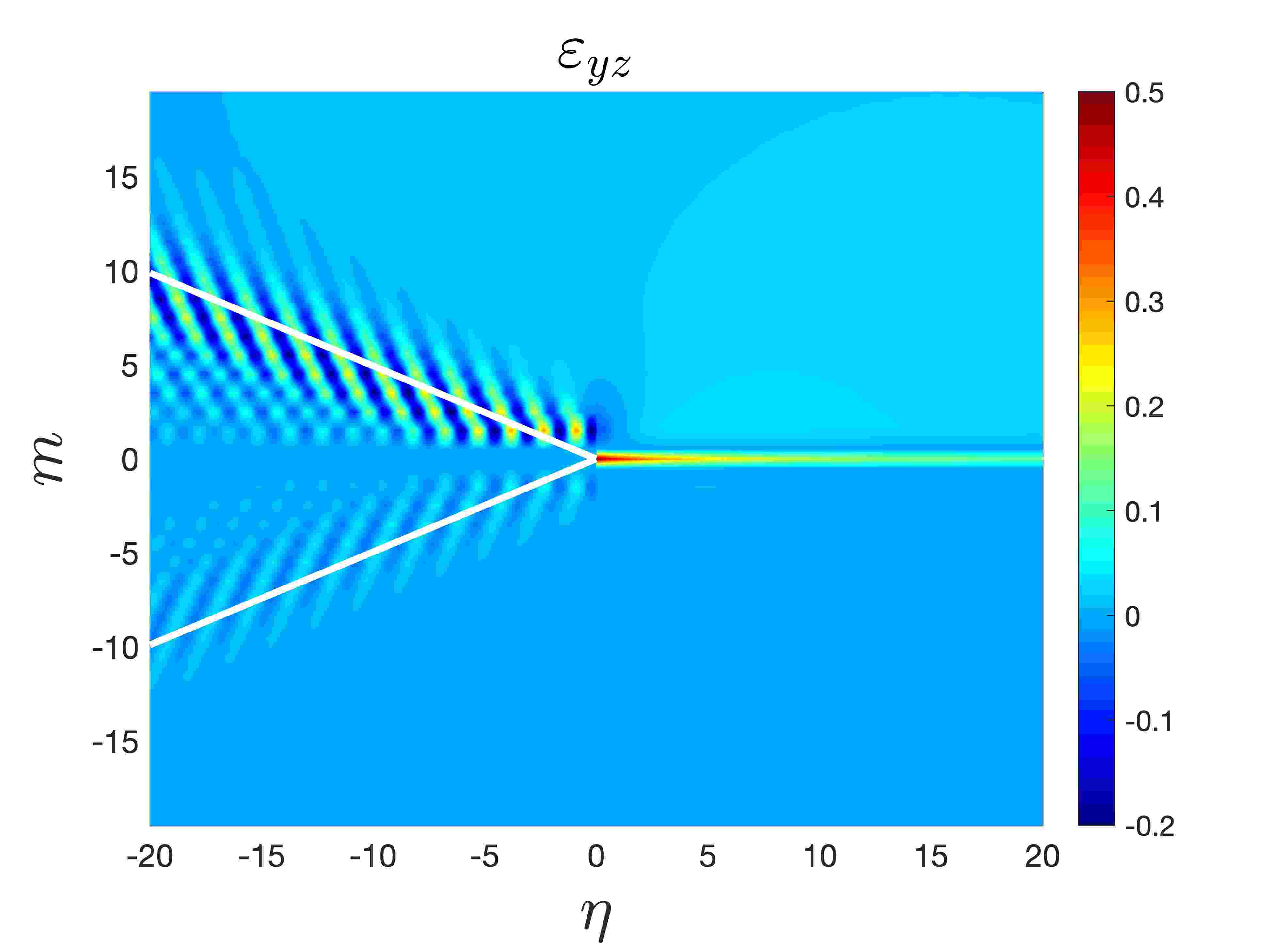
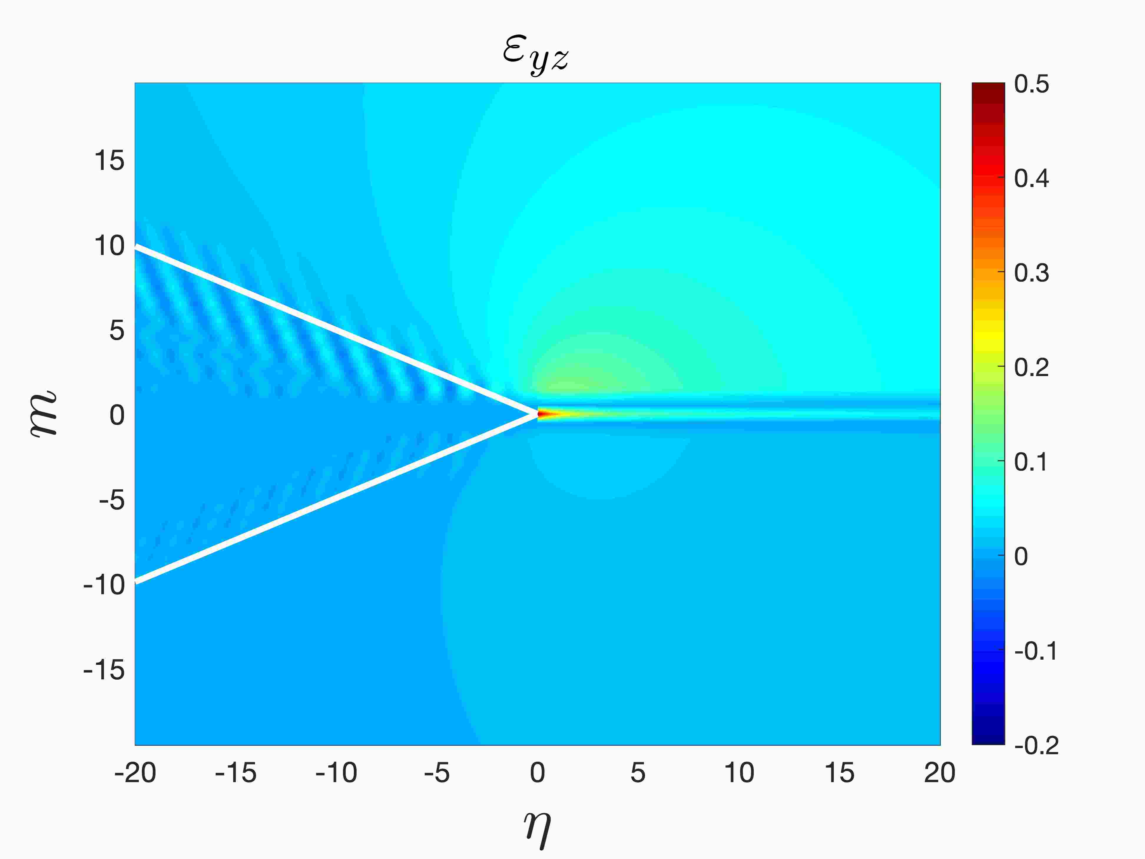
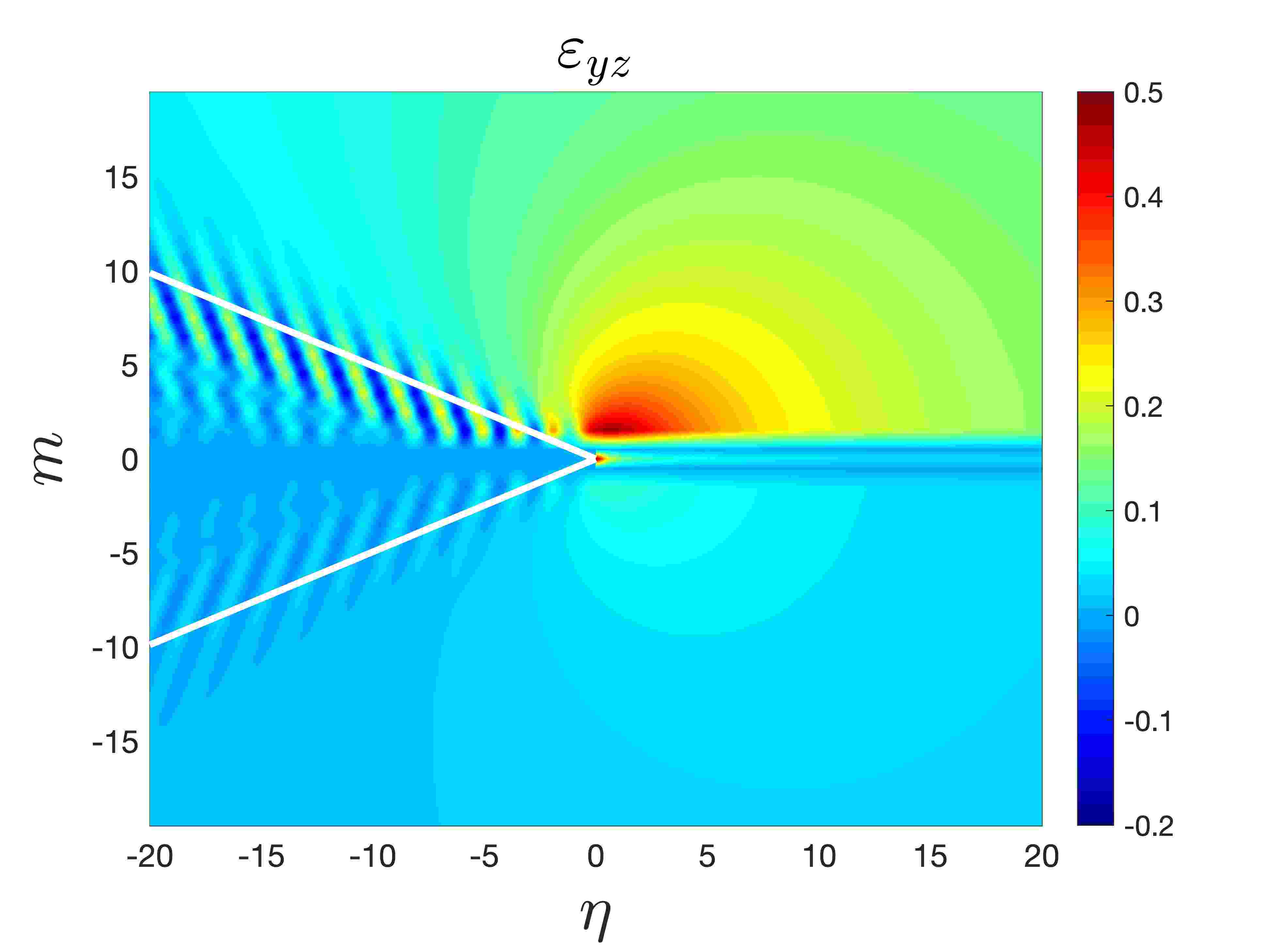
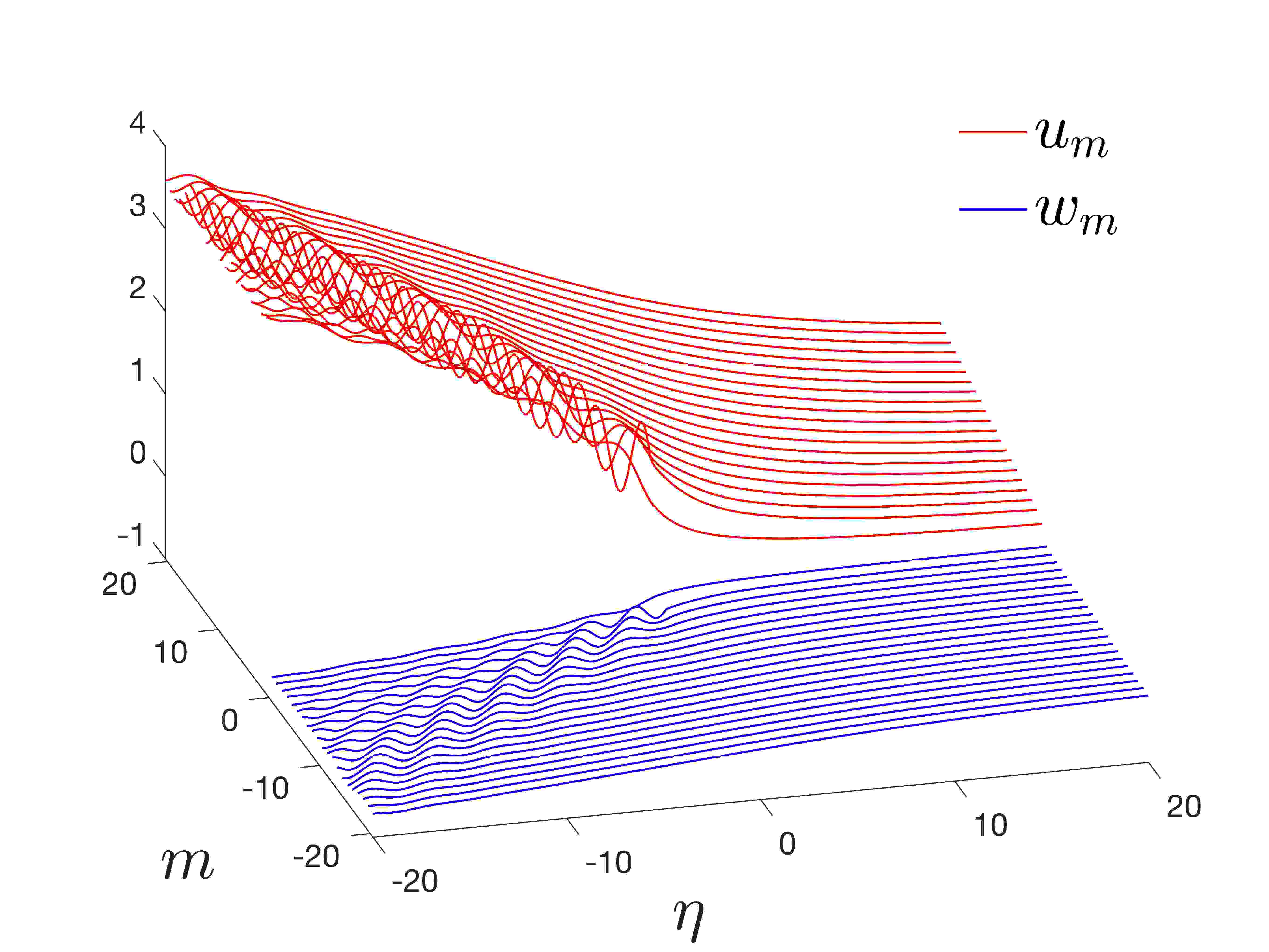
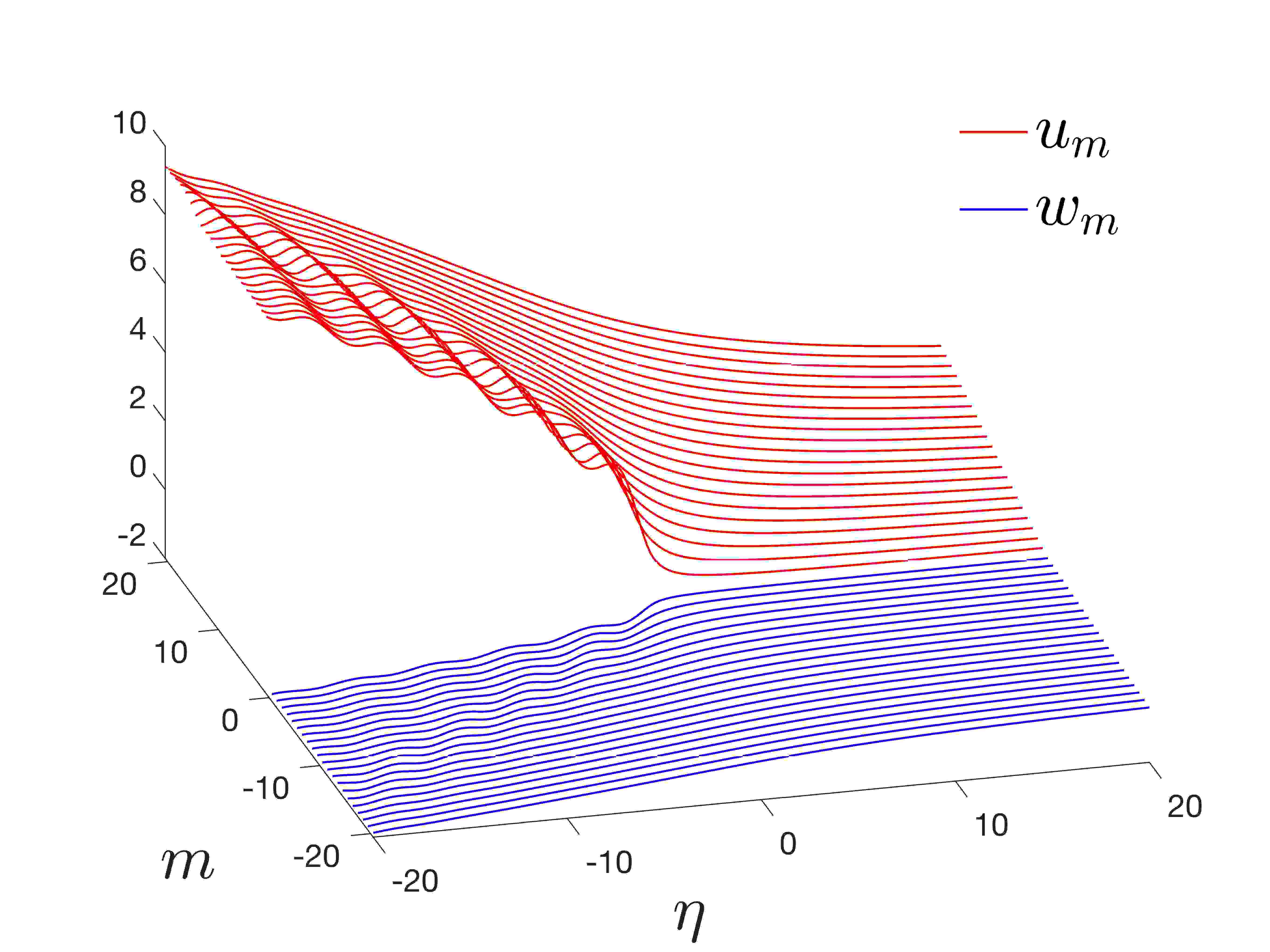
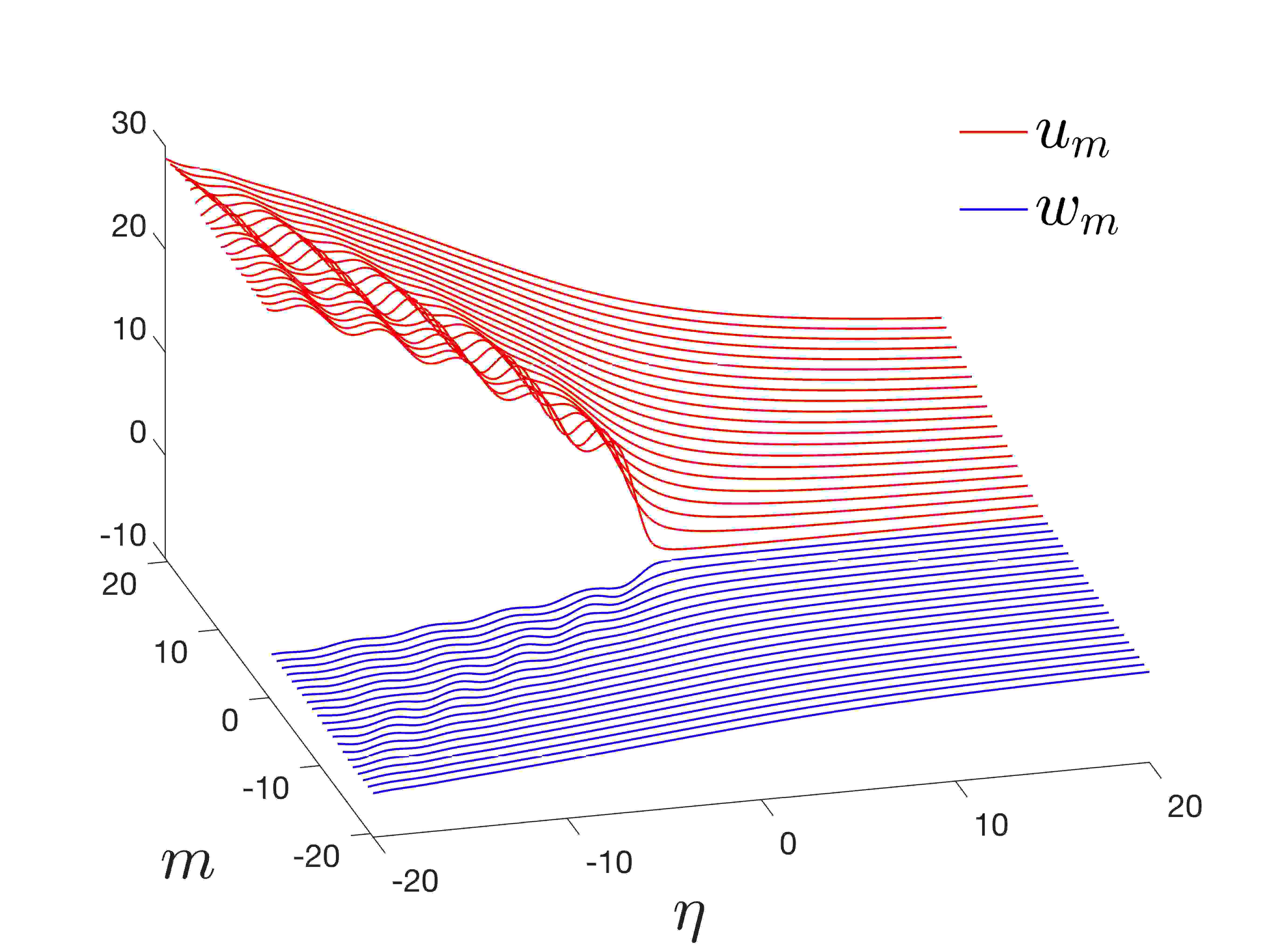
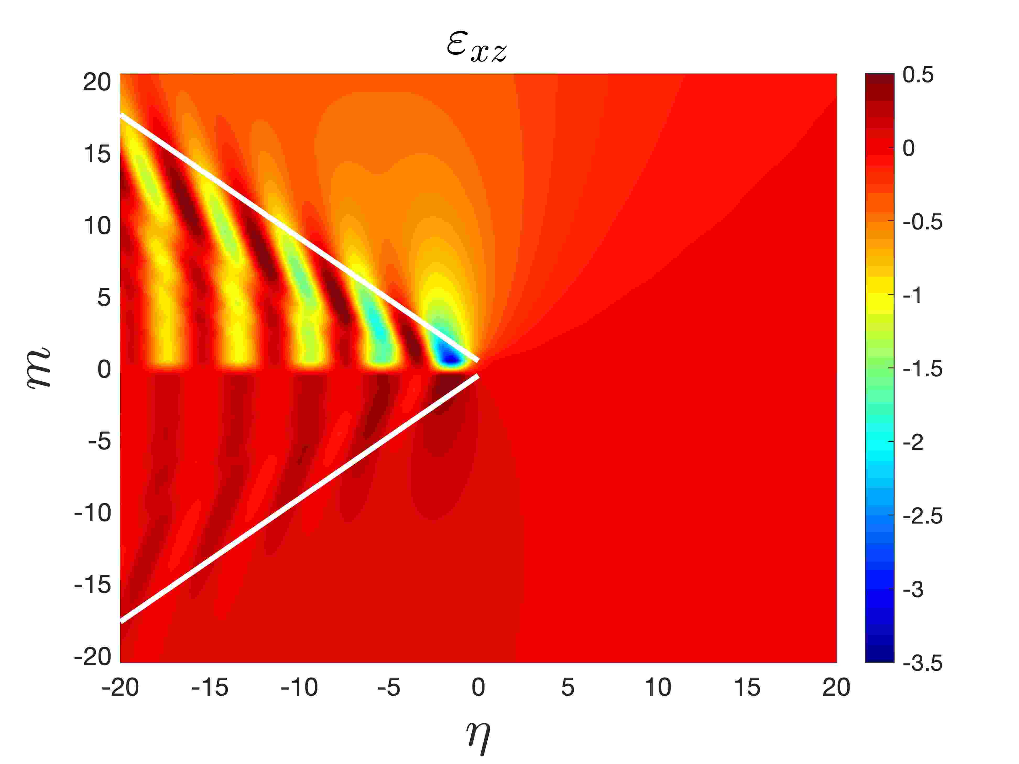
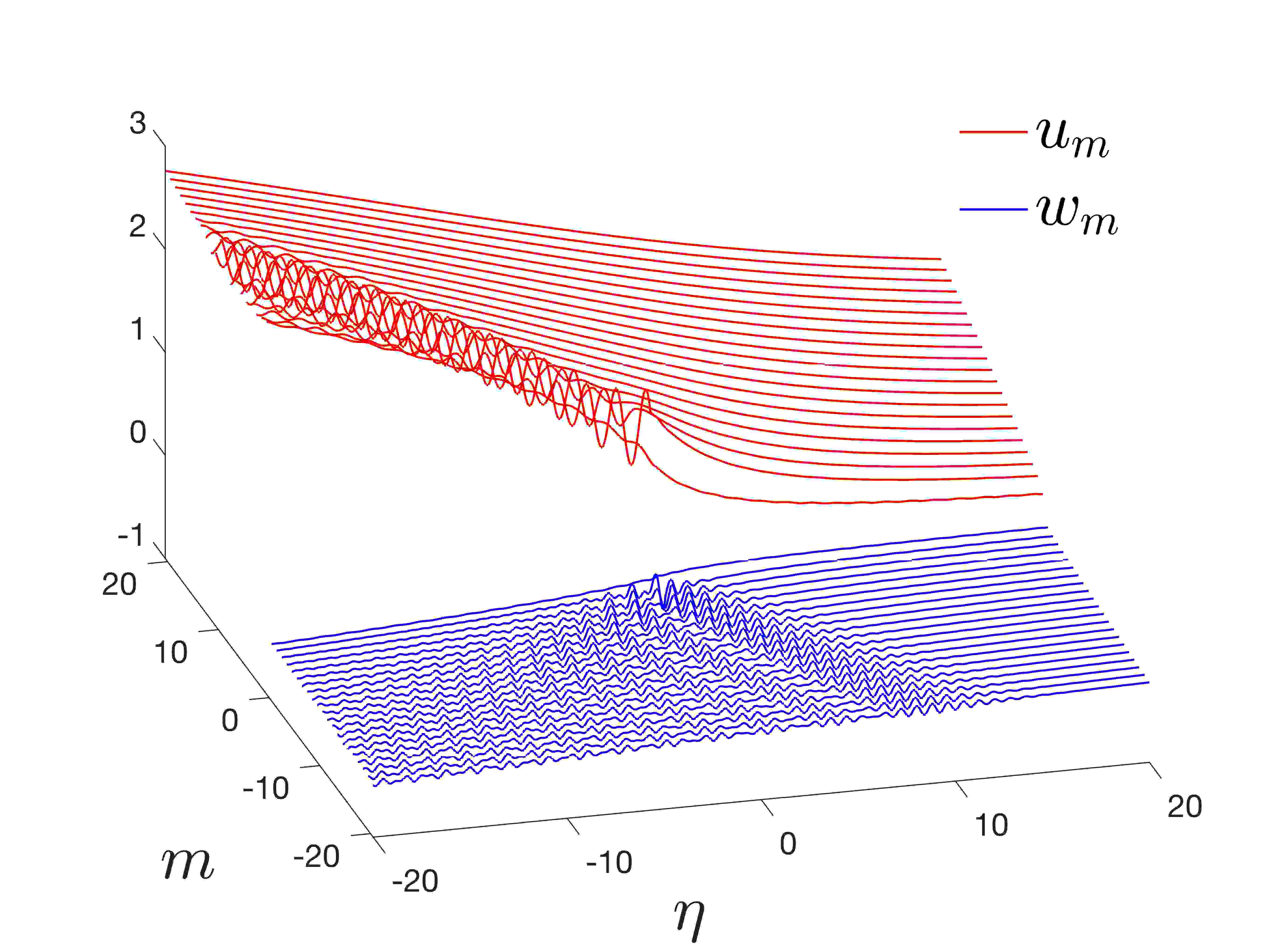
Figures 11(a)–(c) show the lattice displacements for . There is a substantial difference in the displacements between the upper and lower lattices, as expected, that results from their dissimilarity. Here, the lighter and softer upper lattice deforms more than the heavier, stiffer lower lattice during the failure process. There is also evidence that soft interfaces lead to large deformations, induced by vibration, behind the crack predicted by the solution. Such an example is shown in Figure 11(a) and this solution is admissible.
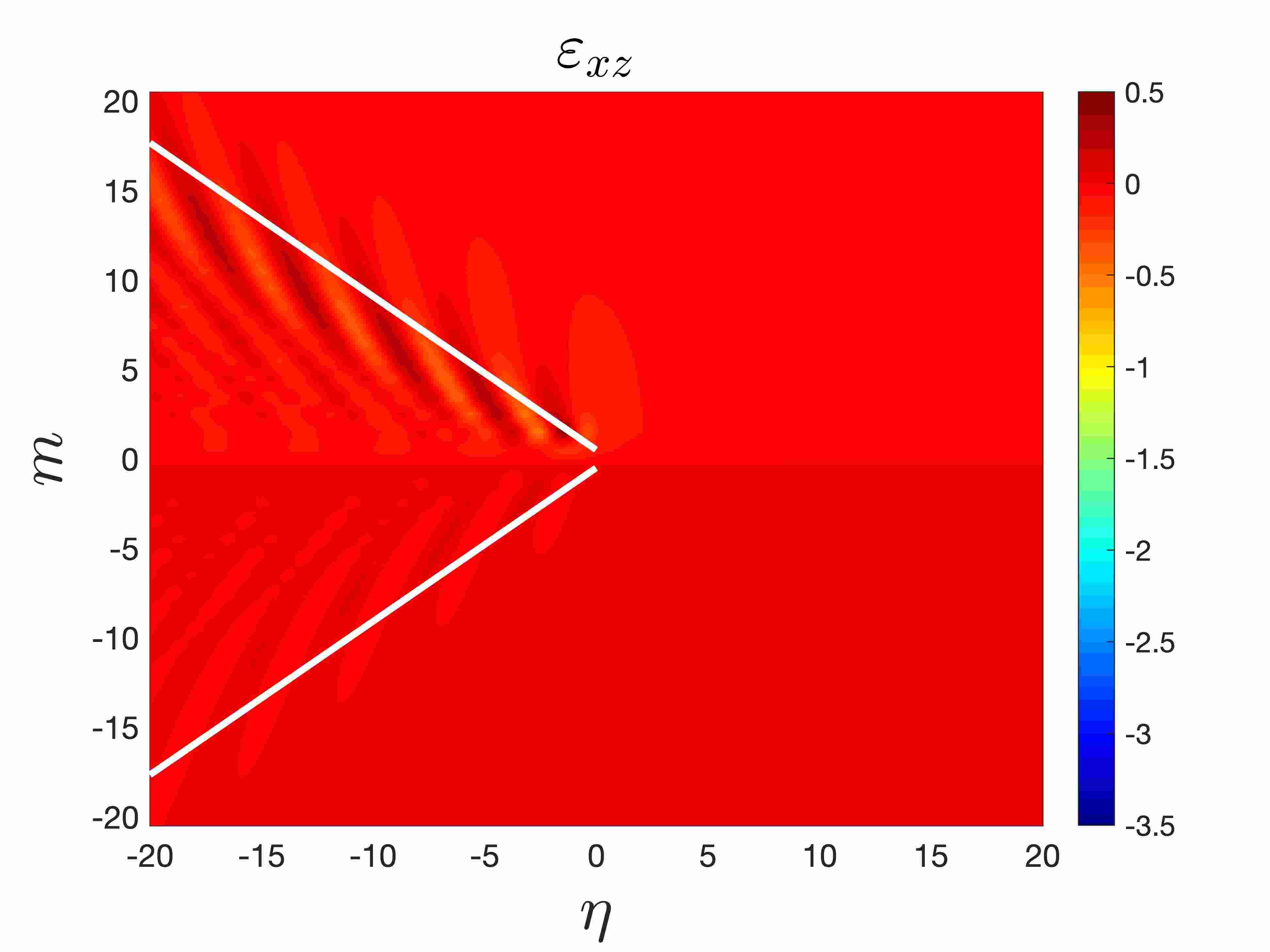
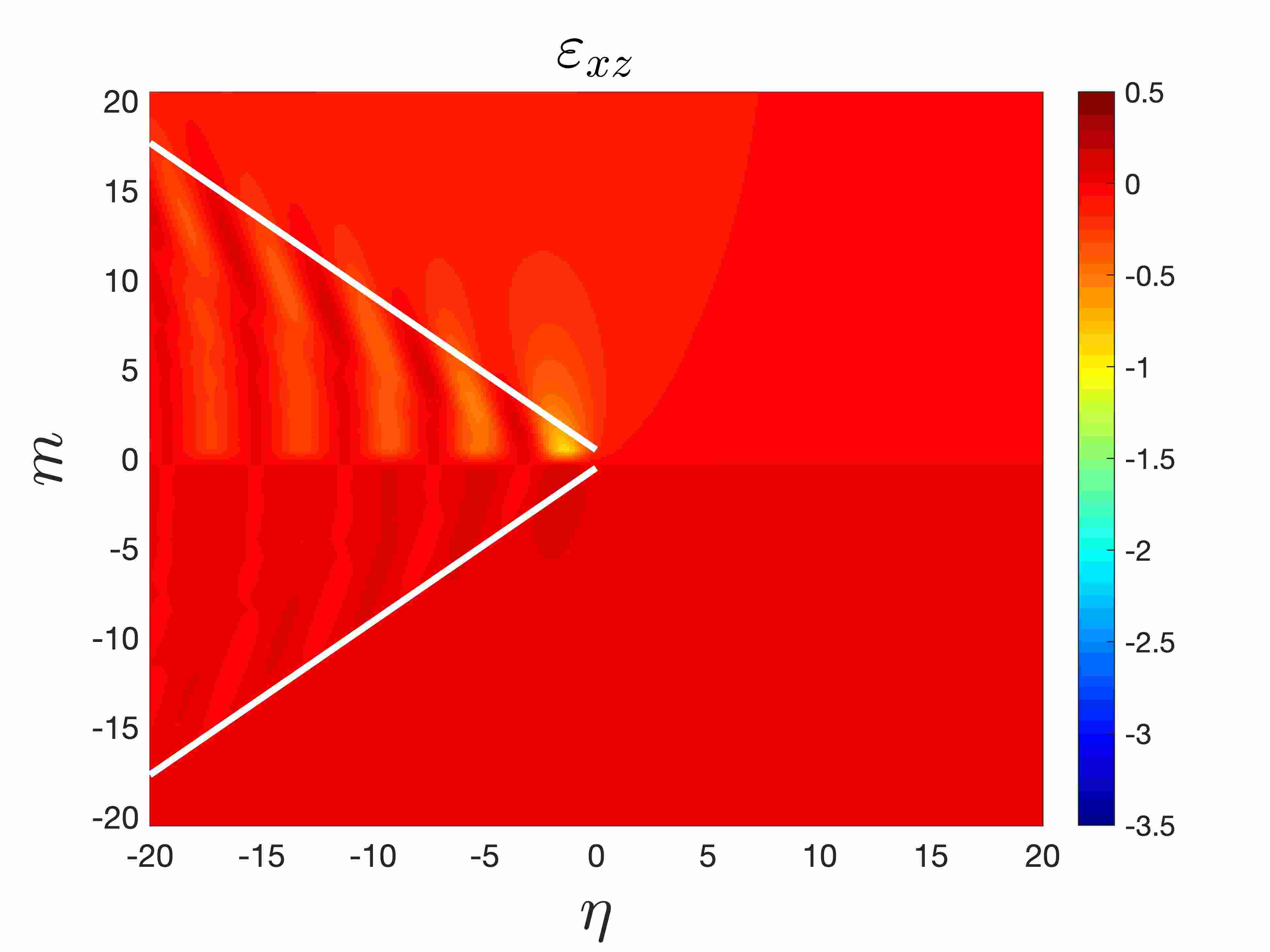
The difference in the behaviour of the upper and lower lattices becomes more apparent when one considers the distribution of strains , as shown in Figures 11(d)–(f). There, as in Section 6.1, vibrations appearing in the wake of the crack tip in the upper lattice are concentrated inside the region enclosed by the crack and the wave radiation ray. The increase in the interface stiffness cause prominent oscillations in the strains that are almost perpendicular to crack faces in the vicinity of far behind the crack tip. These local effects may be attributed the behaviour of the acoustic modes outlined in Section 3, where the lattice with free boundary is considered and waves travelling parallel to the free boundary were identified. In the failure problem considered, those effects are coupled with the those concerning waves propagating along the internal boundary of the dissimilar lattice. Thus, in the problem of the propagating crack, travelling waves must decay to zero in the direction perpendicular to the lattice as .
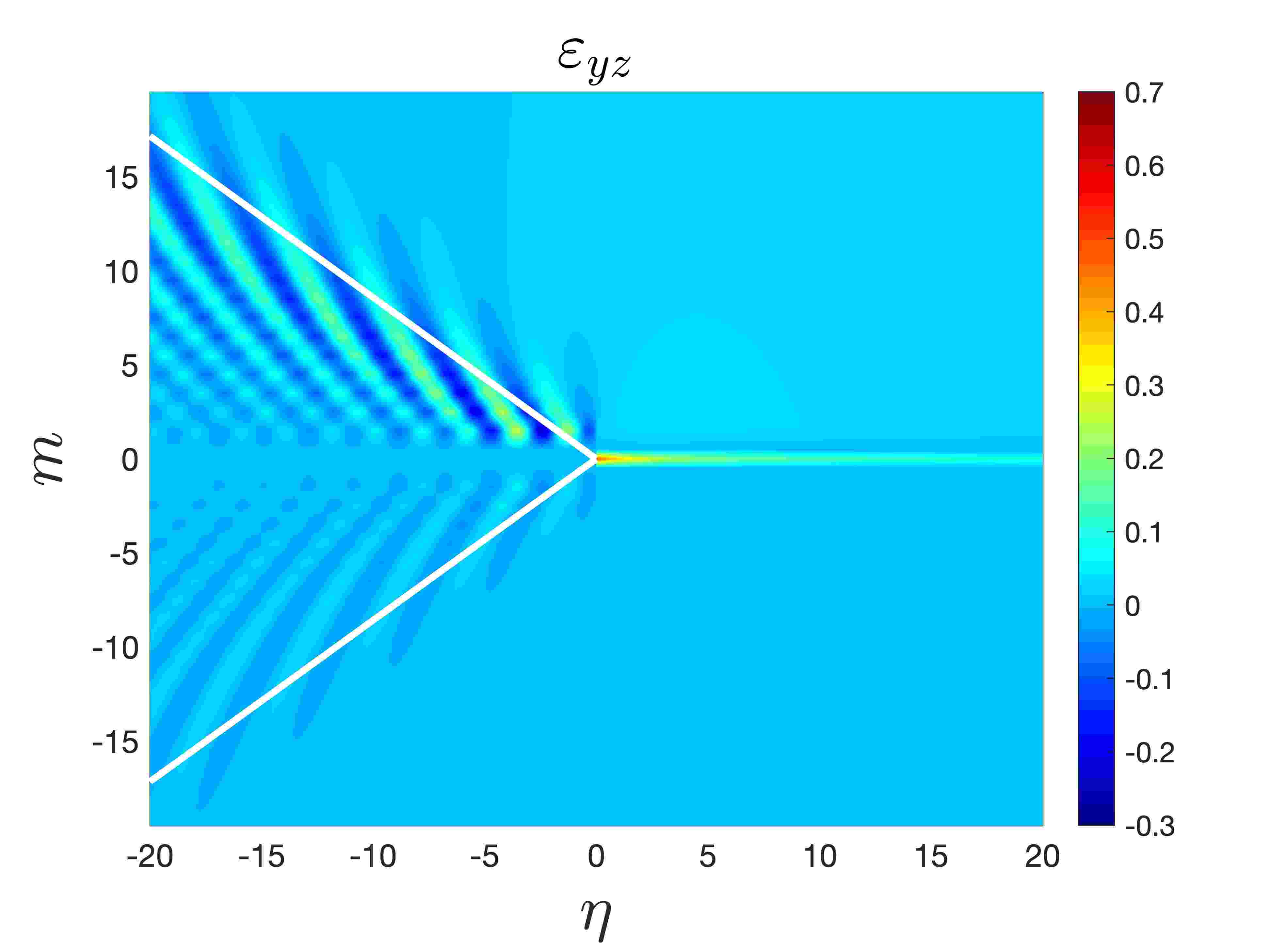
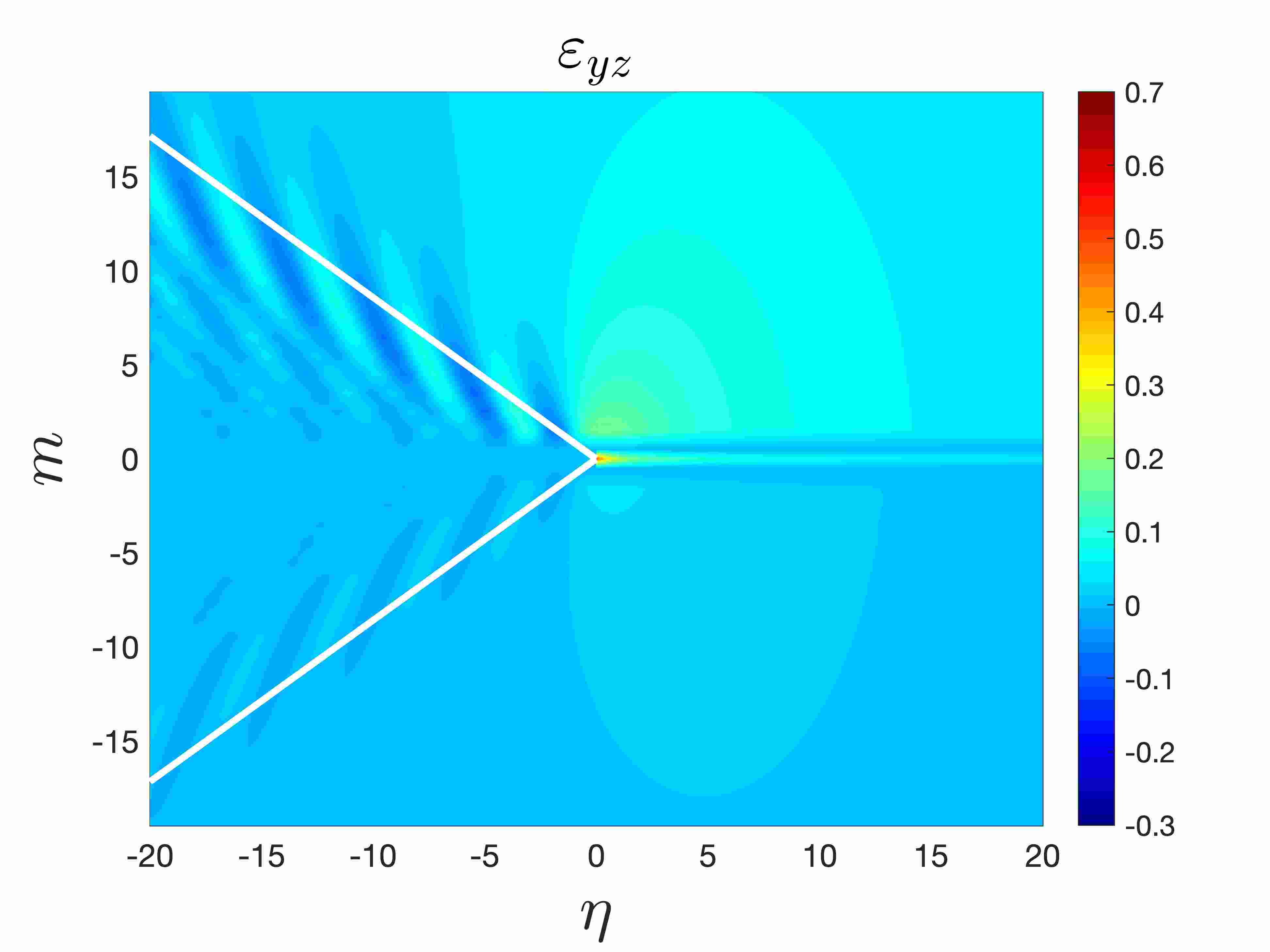
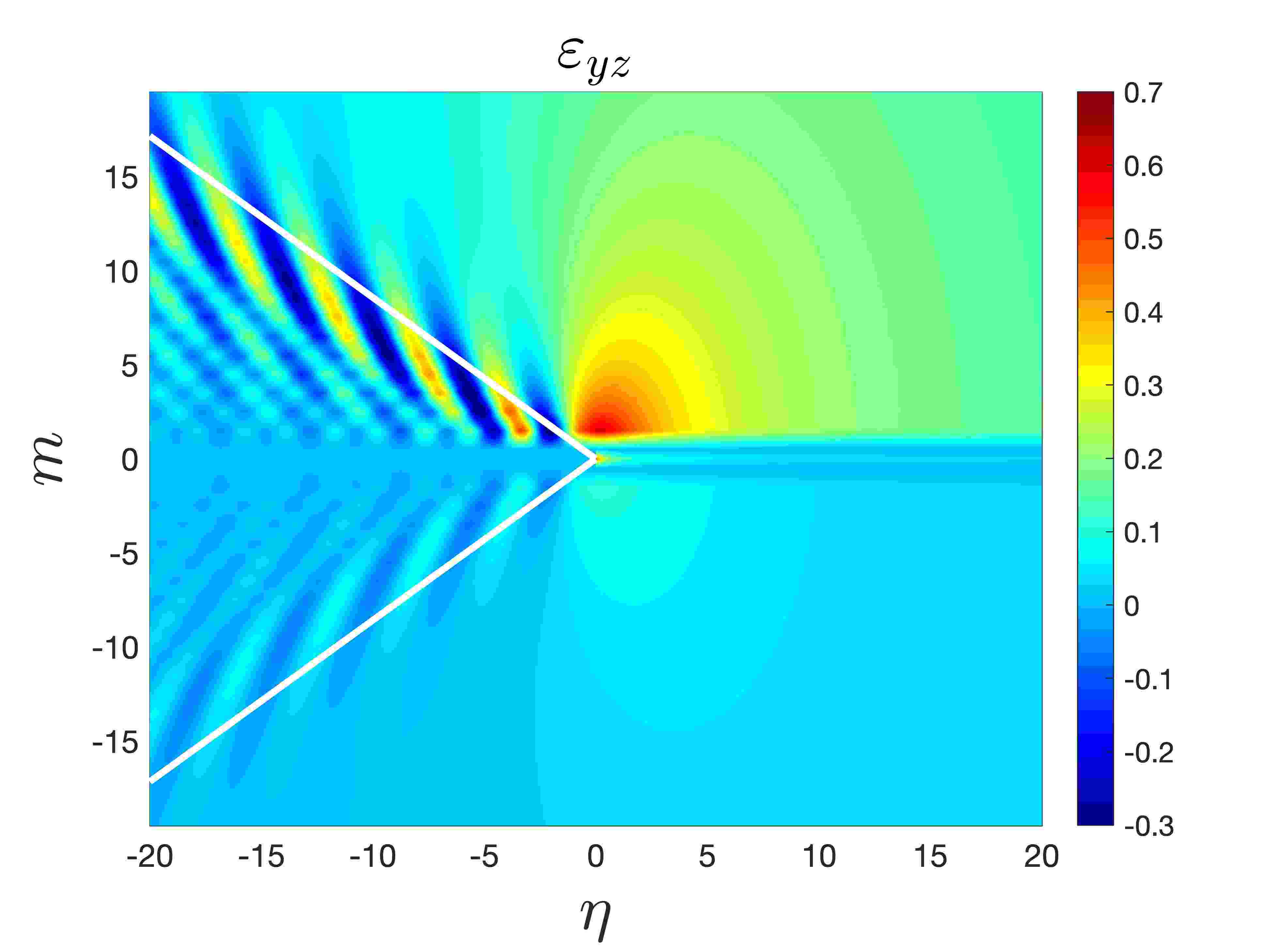
Figures 11(g)–(i) show the the strains , where the effects brought by the far-field waves propagating parallel to the crack in the lower lattice are suppressed. However, these strains reveal the preferential directions taken by the vibrations propagating along the wave radiation rays and whose intensity increases with increase of the interface stiffness.
Note that Figures 11(g)–(i) show that due to the dissimilarity of the lattices and their responses, the strain is also concentrated at the crack tip and ahead of the crack. For soft interfaces this effect is the most prominent as the bulk lattice effects are quite small in comparison. As the stiffness of the interface is increased, effects such as micro-structural vibrations and localised deformations within in the bulk lattices become more noticeable. In particular Figure 11(i) shows the emergence of a region local to the crack tip possessing comparable deformations. In fact, our definition of admissibility allows for such a phenomenon. Indeed, if one checks the admissibility conditions (29) along the interface, then they will be satisfied. If simultaneously, the toughness of this upper lattice is much higher than the interface toughness then the fracture will occur along the interface only. However, if the toughness of the upper lattice is comparable to the interface such a scenario may lead to the deflection of the crack into the softer lattice.
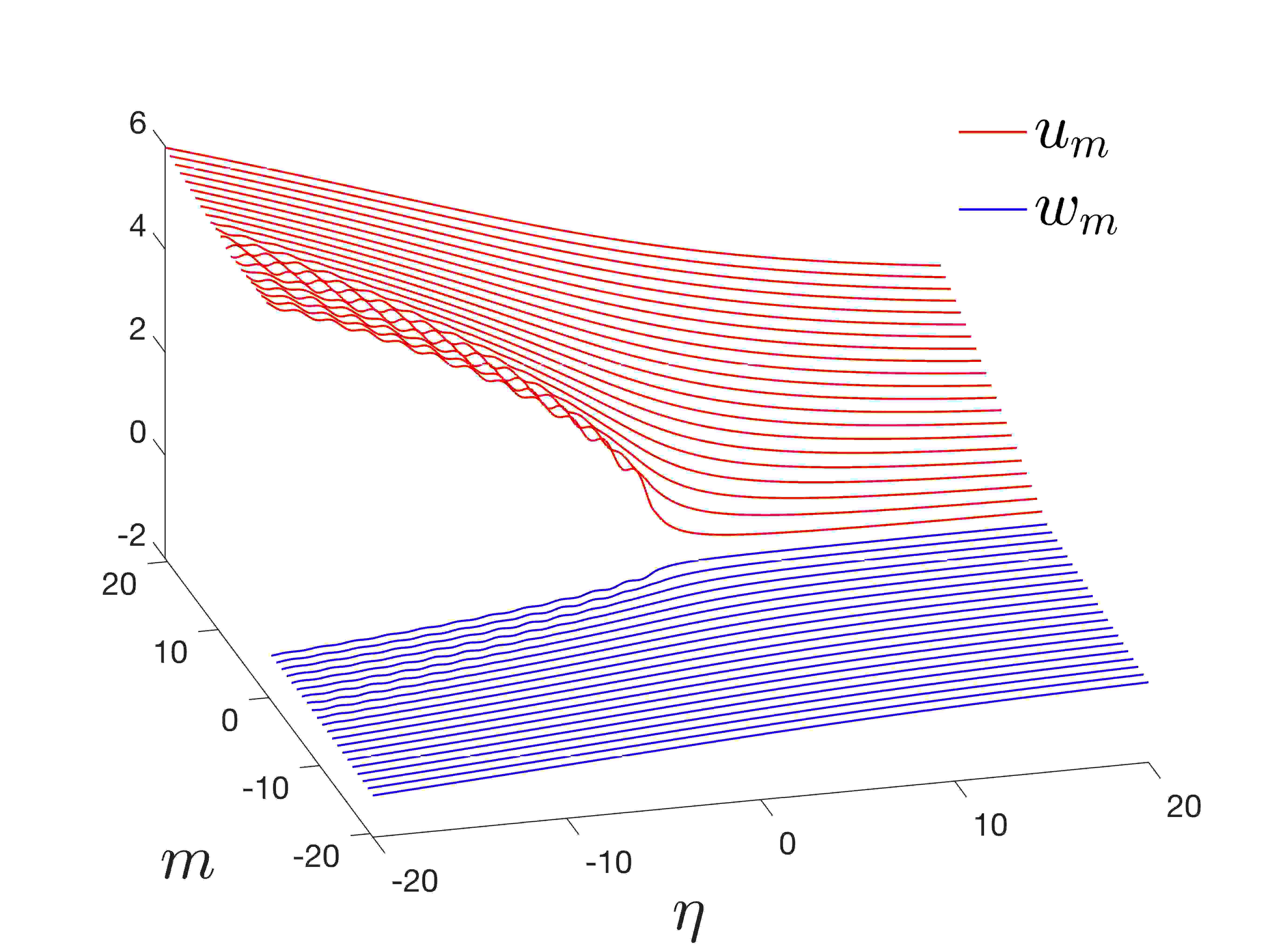
In Figure 12, we consider the dissimilar lattice behaviour when a crack propagates with a higher speed. As in Sections 6.1, increasing to the crack speed leads to more significant lattice deformations and a wider crack opening, as evidenced by lattice displacements Figures 12(a)–(c). Similarly to Section 6.1, the increase of the crack speeds leads once again to wave radiation rays, symmetric about the crack path and separated by a larger angle than in Figures 11. In comparison with that case (see Figures 11(e), (f) and 12(e), (f)), this results in a weaker localisation of the field in the upper lattice. The effect is also observed for the strains in Figures 12(h) and (i). For the lower lattice, we again encounter vibrations with a wavefront perpendicular to the crack and that decay slowly in the same direction. In addition, the vibrations induced by the crack propagating at high speed have a longer wavelength than those identified in Figure 11.
6.3 Essentially different dissimilar lattice system with an interface
Next, we investigate the case when the upper and lower lattices possess different wave speeds and are either perfectly connected or connected through an imperfect interface.

The computations are now performed for a lattice system characterised by and . We again choose the interfacial bond stiffness to be , 1 and 5. Here, the cases and represent the perfect joining of a soft and stiff lattice at and , respectively, (see Figure 1).
We first consider the behaviour of ratio for these structures in Figure 13. As a function of , this ratio possesses similar properties as those described in the previous sections. Here for , by comparison with Figures 7 and 10, it appears the lattice dissimilarity leads to a reduction in the size of the speed intervals for admissible propagation regimes satisfying (29). In addition, for the high interfacial bond stiffness the resulting admissible speed regimes are represented by a collection of disjoint intervals, as evidenced by the case in Figure 13. The overall size of the union of these intervals is again less than the size of the continuous interval describing the admissible regimes in Figures 7 and 10 for . As shown in Figure 13 for , these disjoint intervals may also coincide with the non-smooth behaviour of . Once more, each curve in Figure 13 is supplied with crosses at two particular speeds corresponding to admissible regimes for failure that are further investigated in Figures 14 and 15.
(a)
 (b)
(b)
 (c)
(c)
(d)
 (e)
(e)
 (f)
(f)
(g)
 (h)
(h)
 (i)
(i)
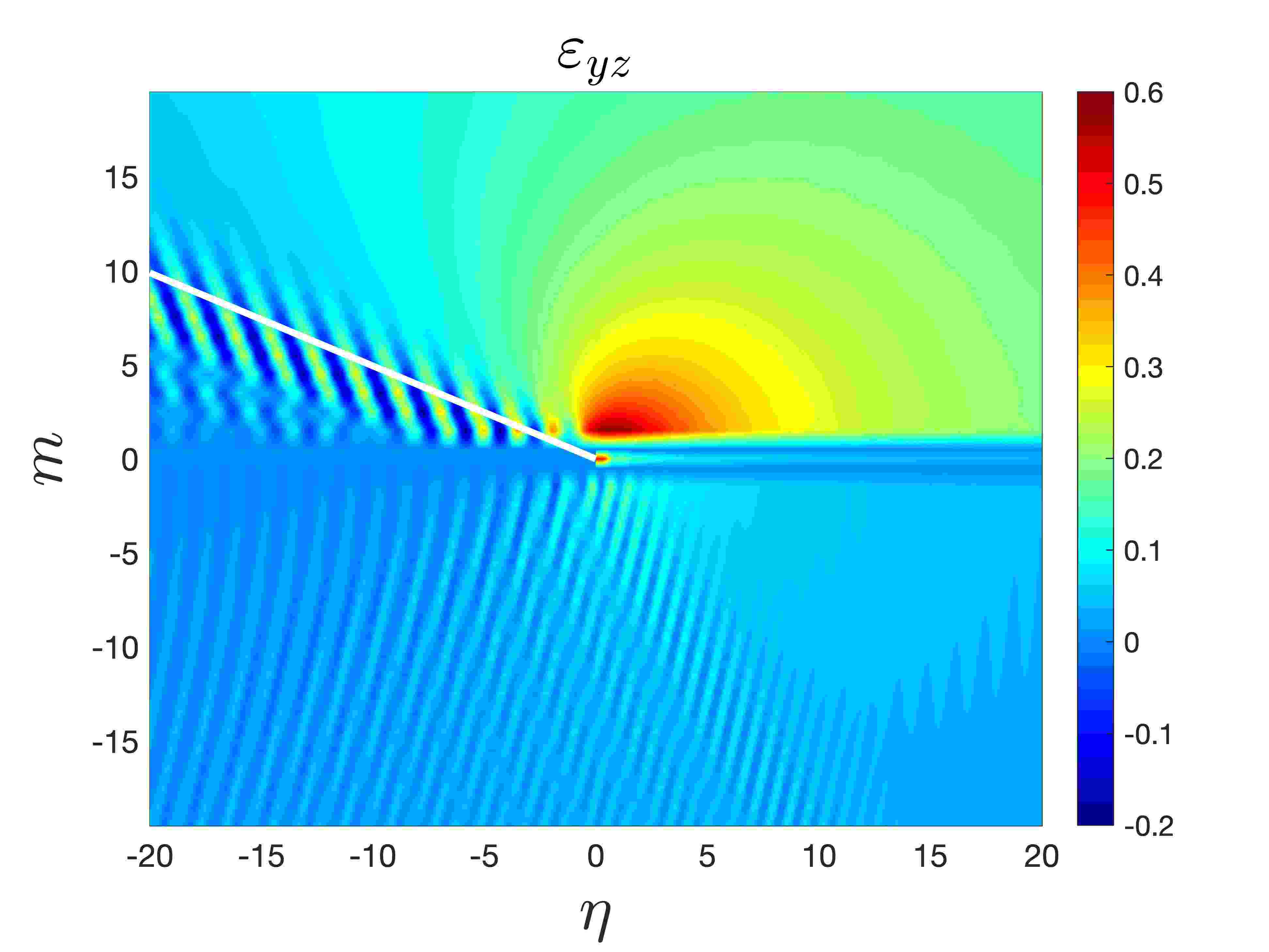
(a)
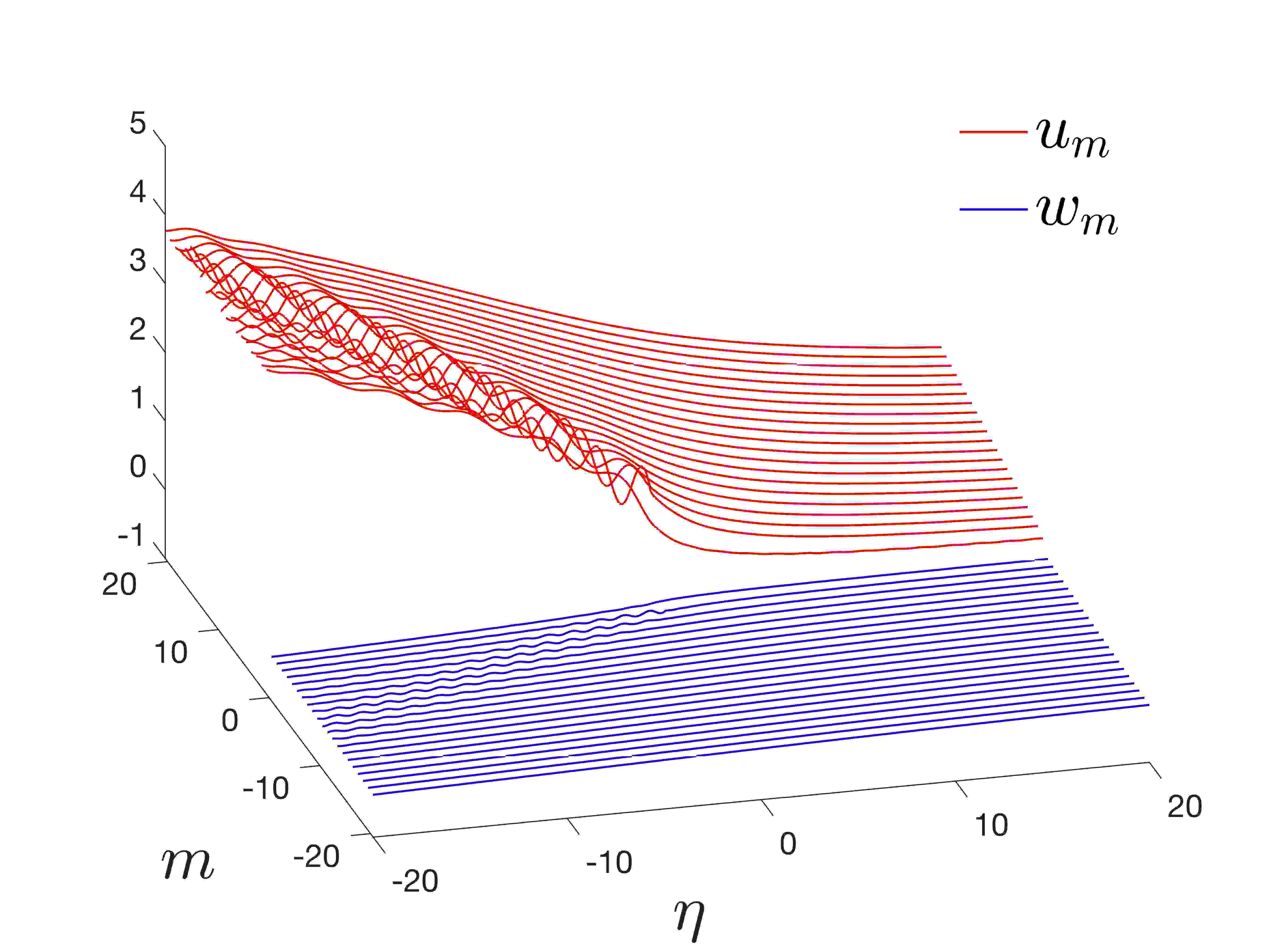 (b)
(b)
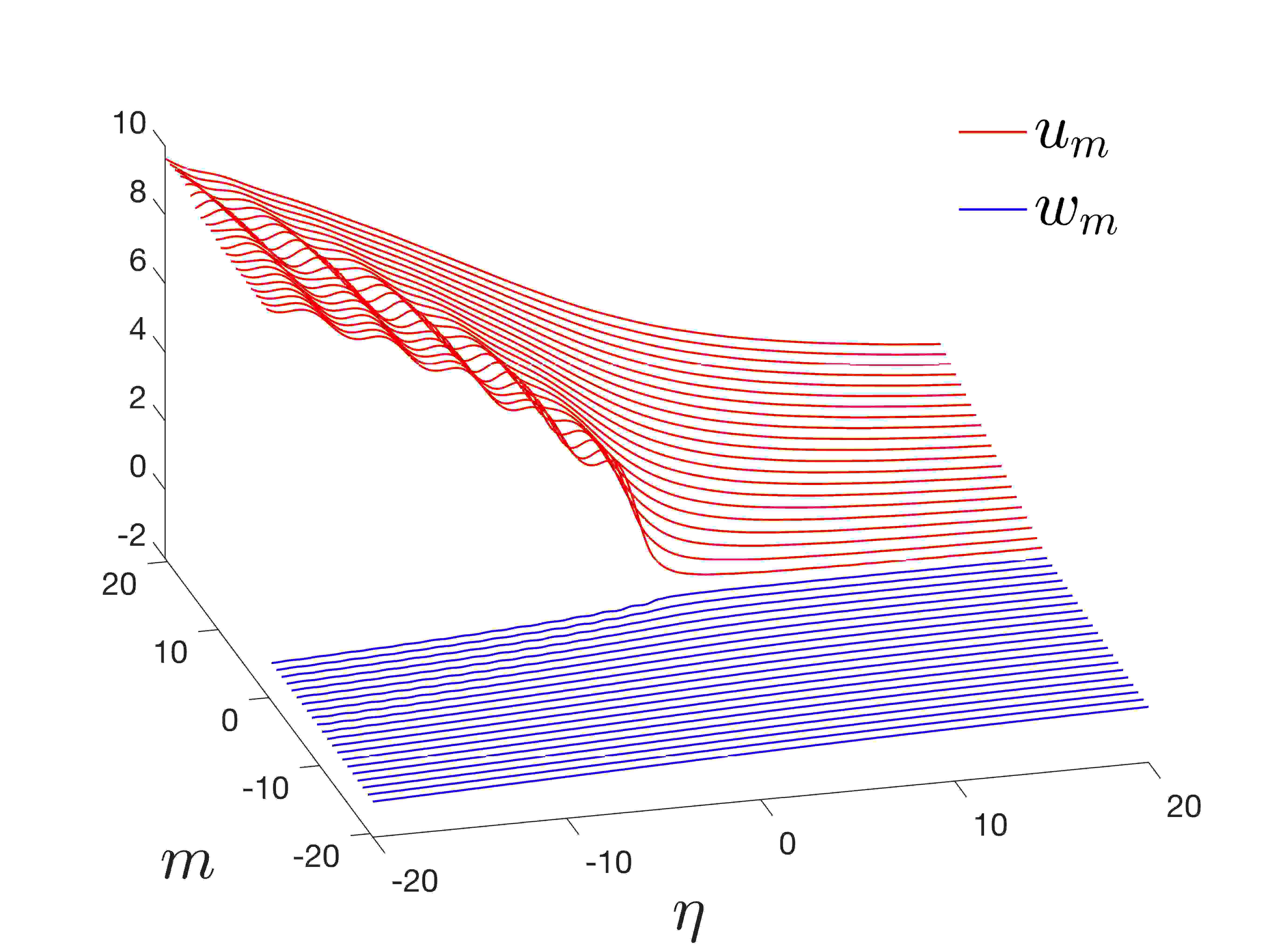 (c)
(c)
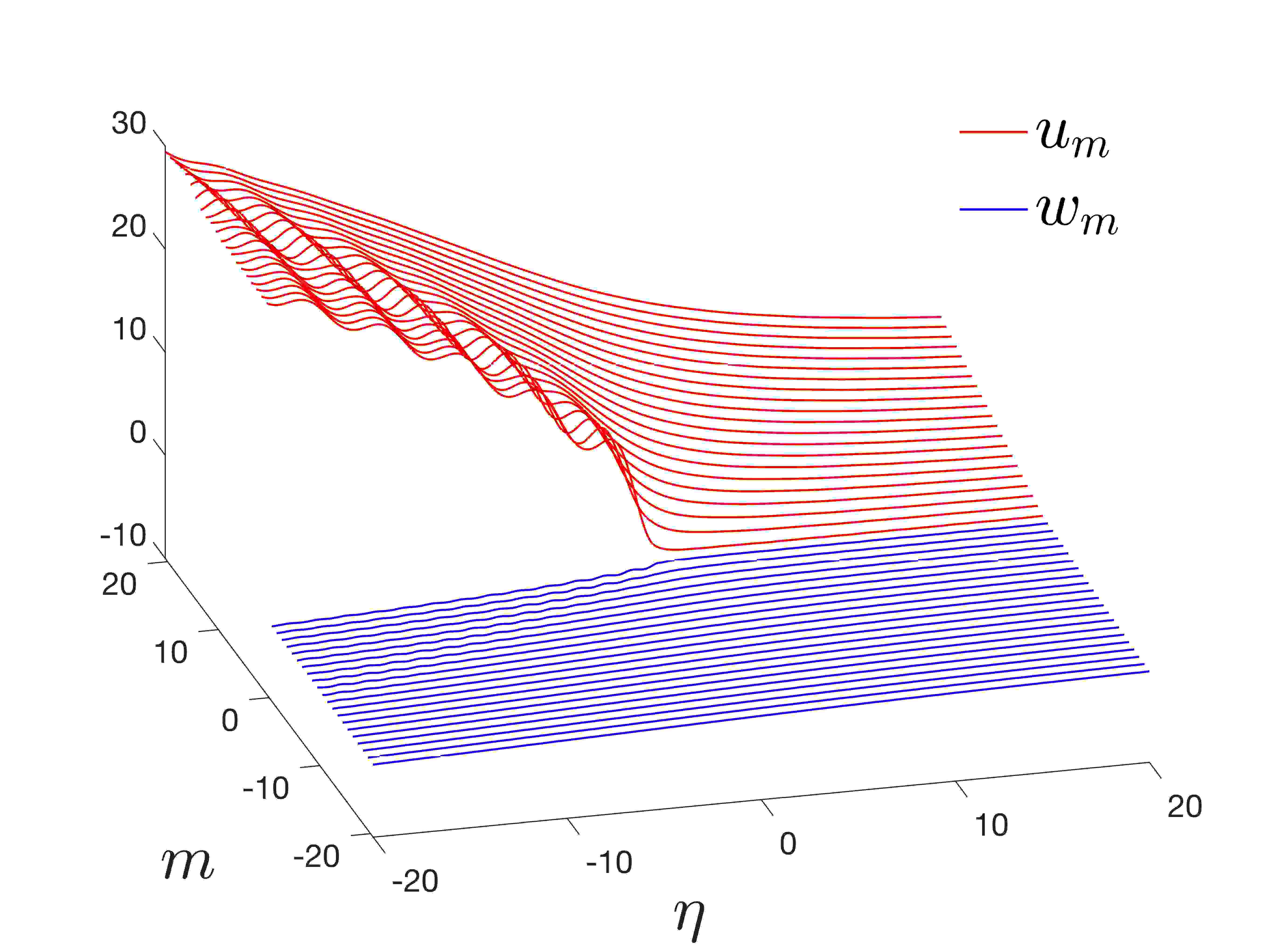
(d)
 (e)
(e)
 (f)
(f)
(g)
 (h)
(h)
 (i)
(i)
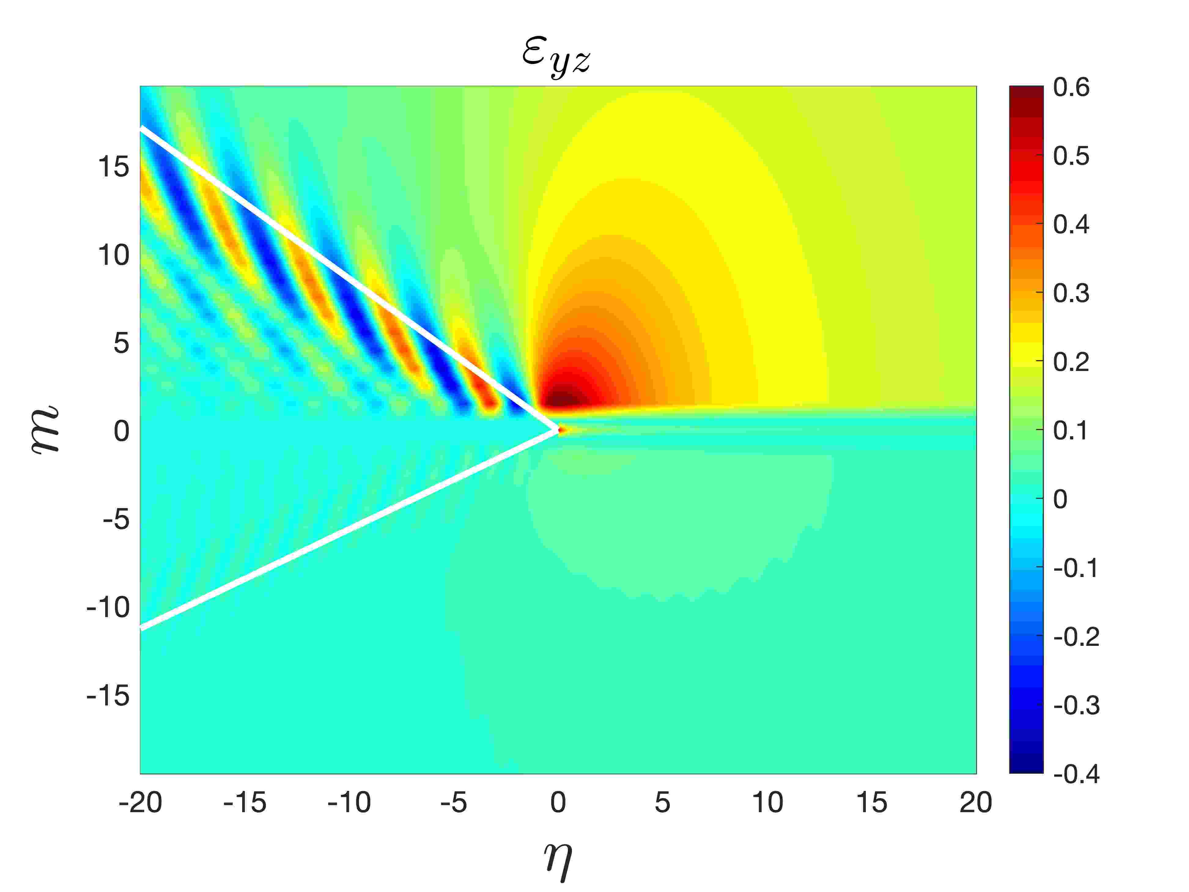
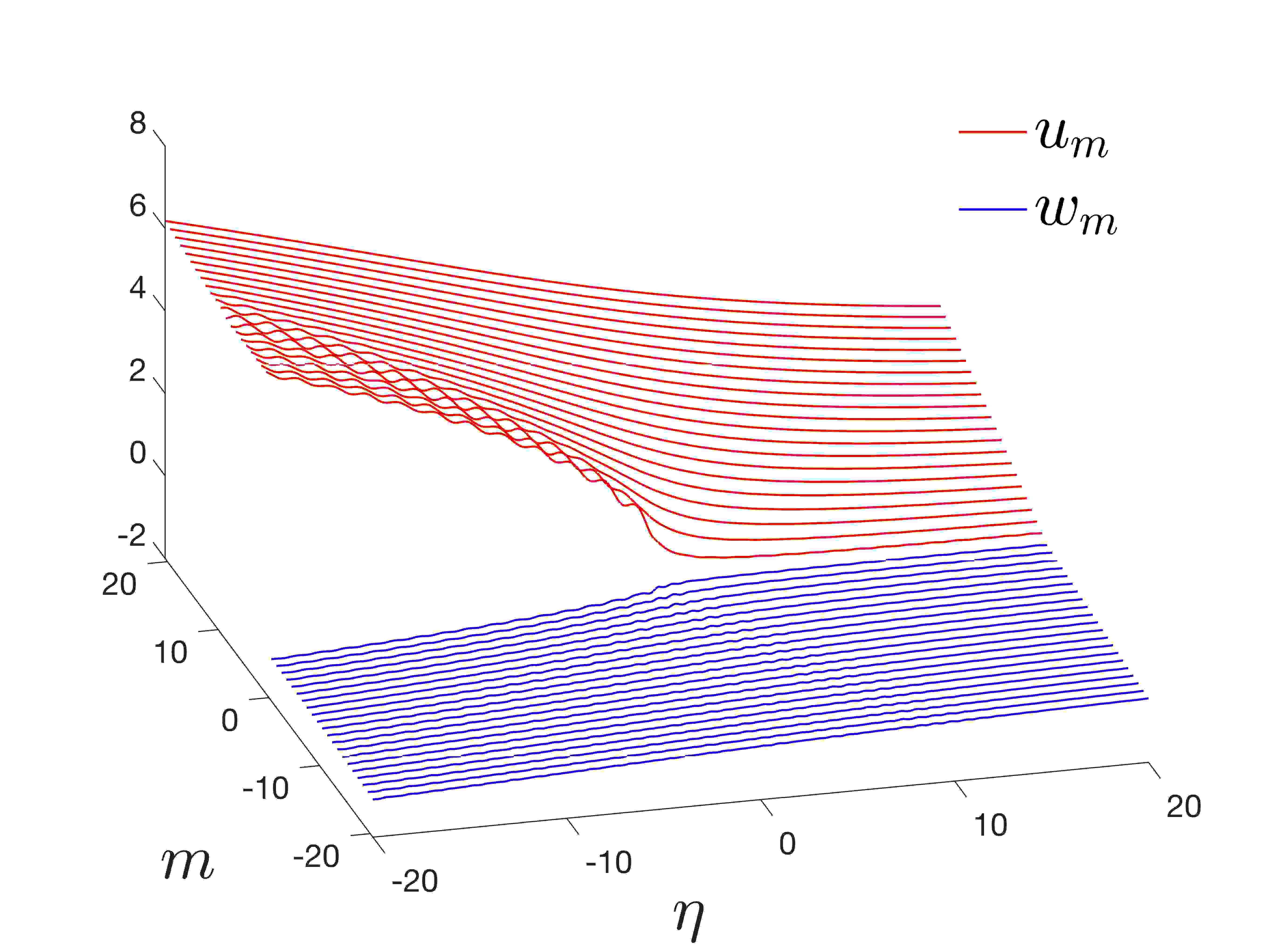
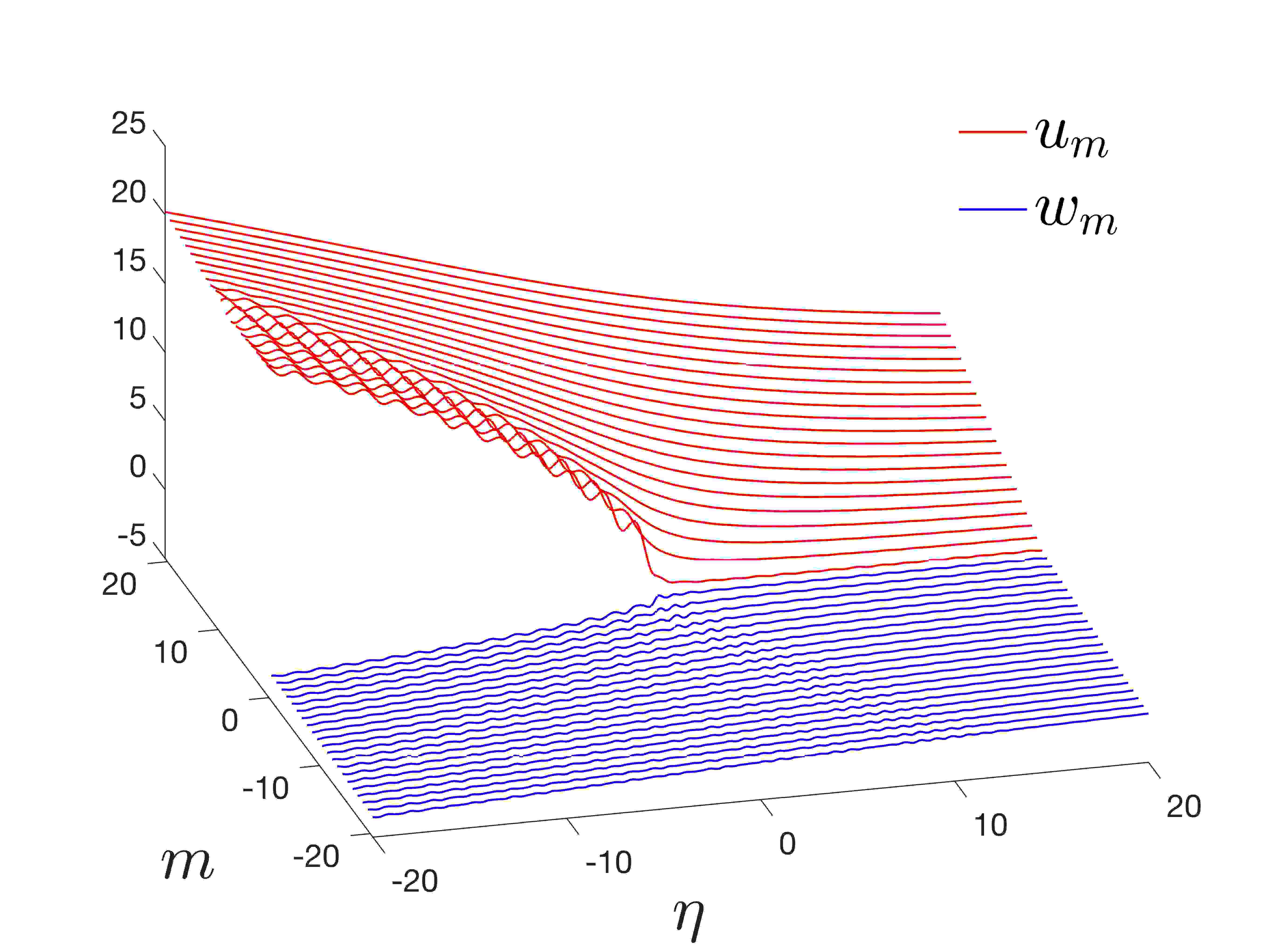
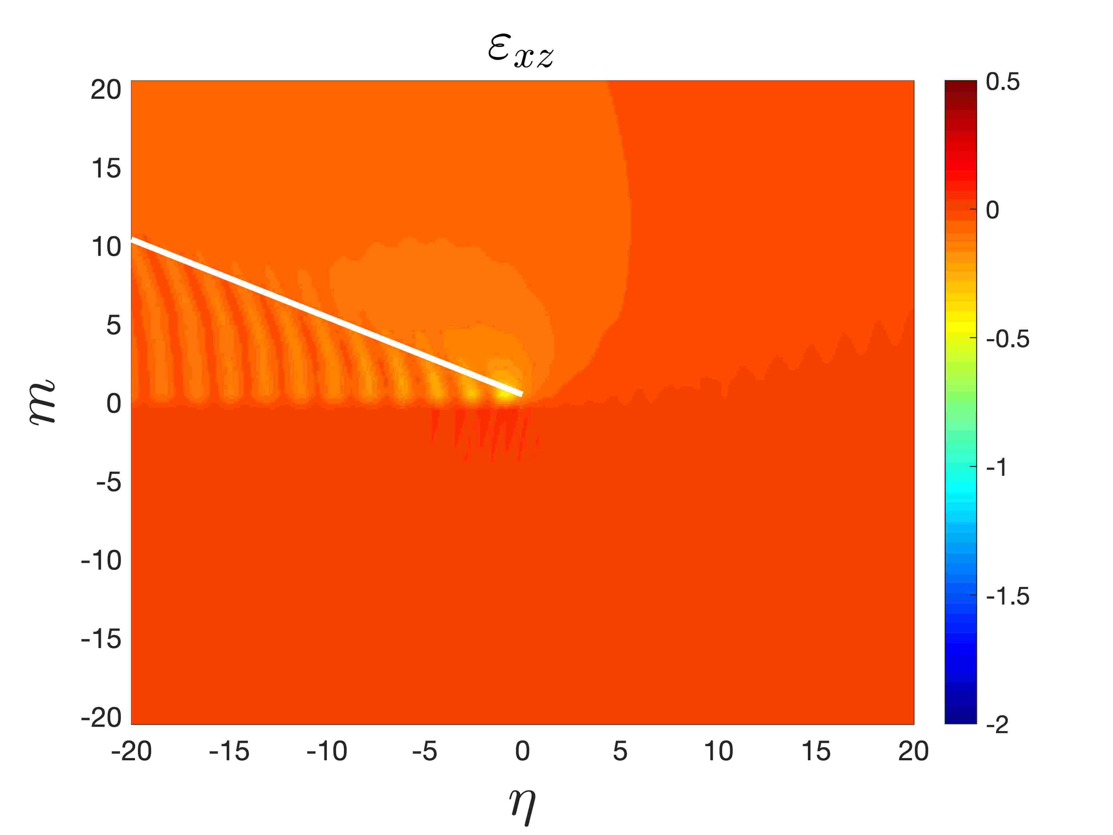
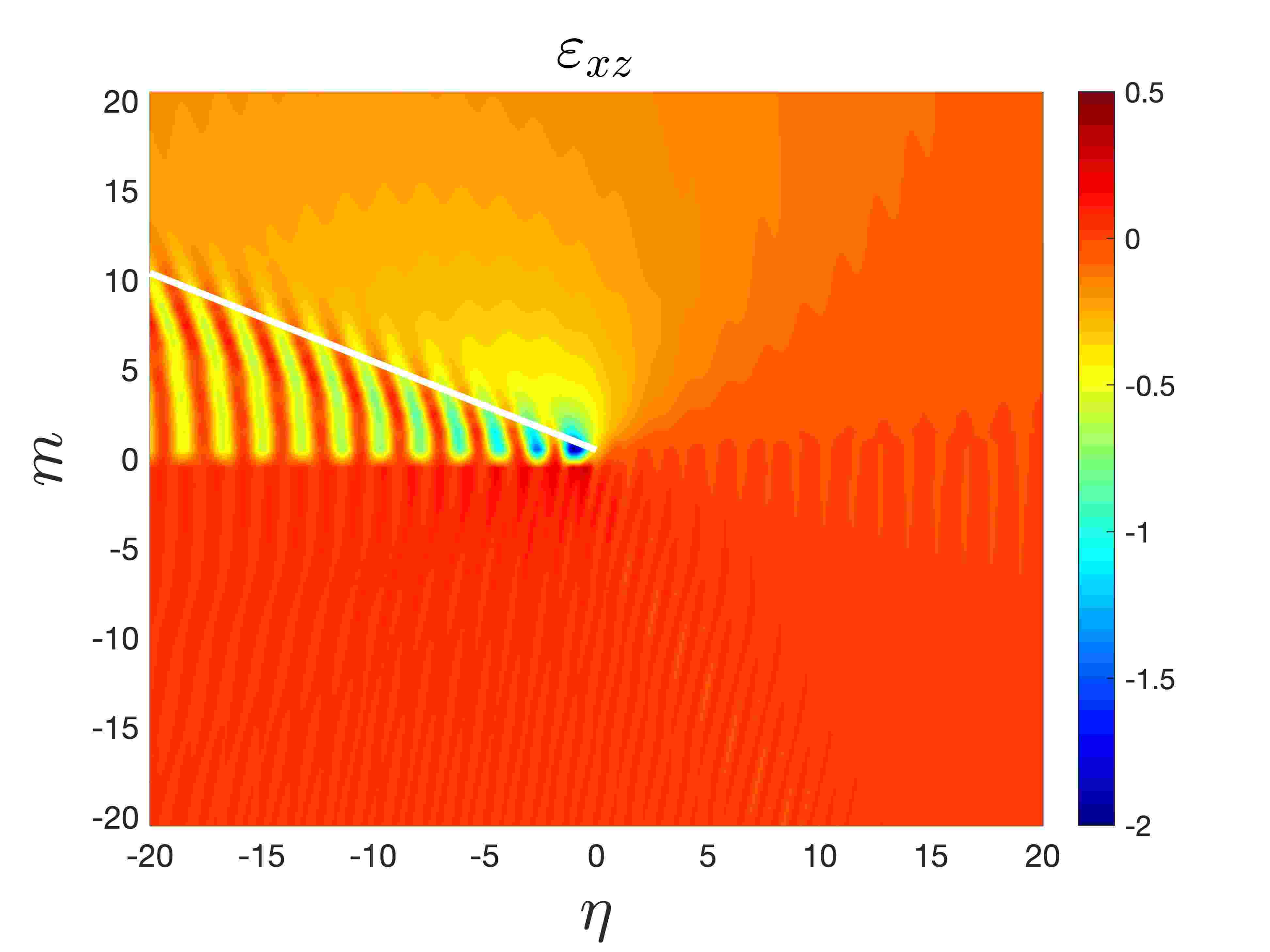
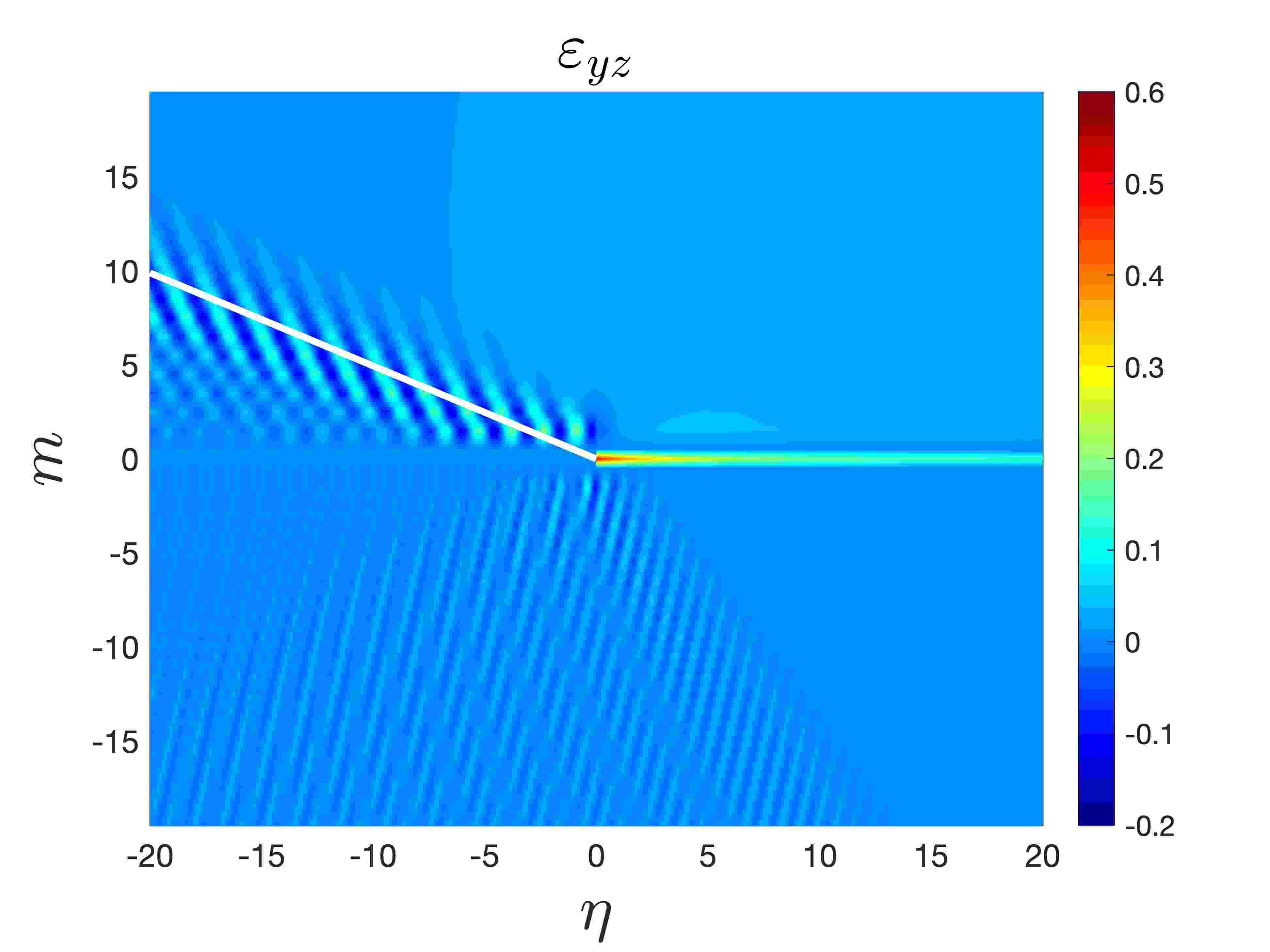
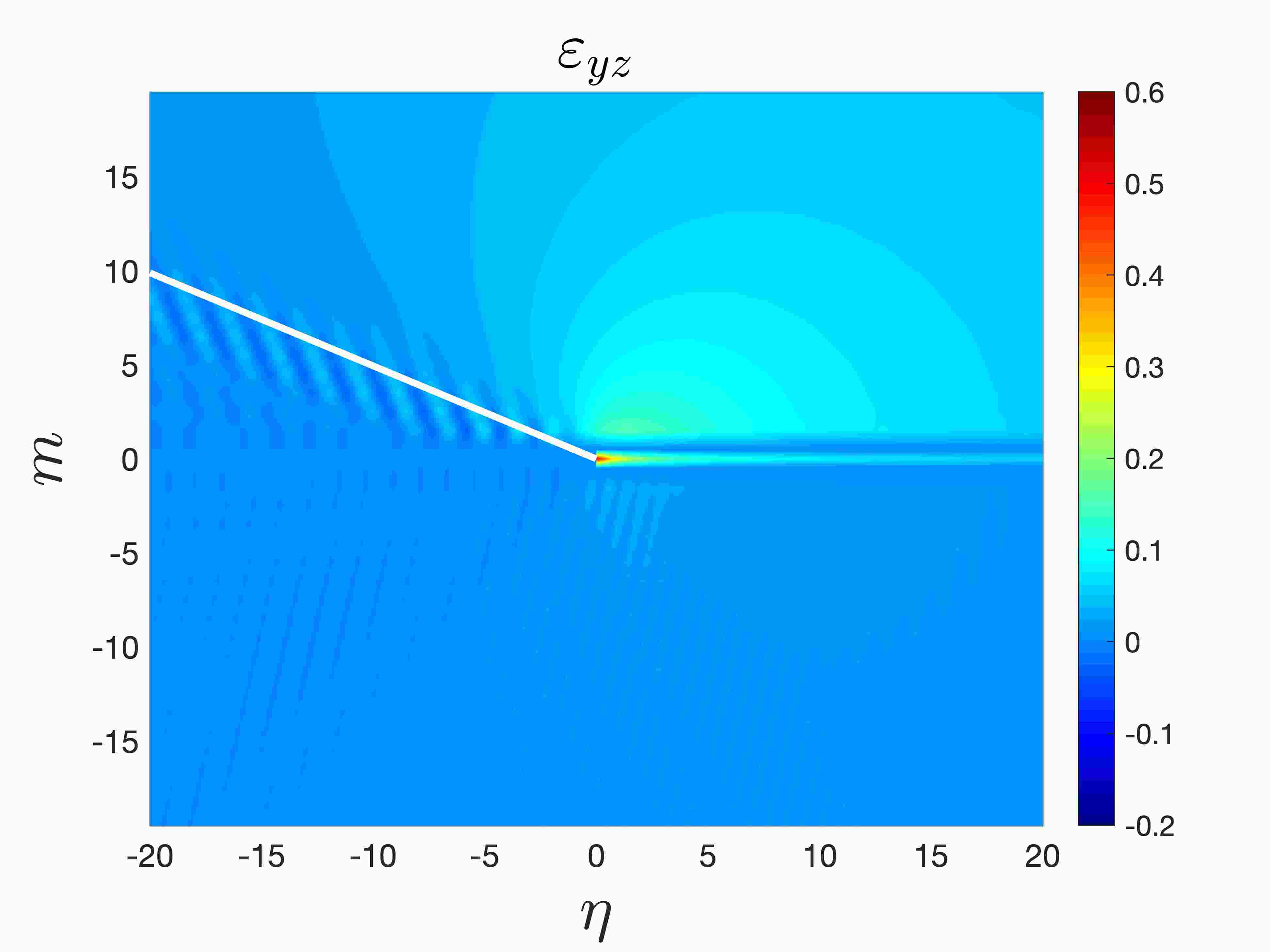
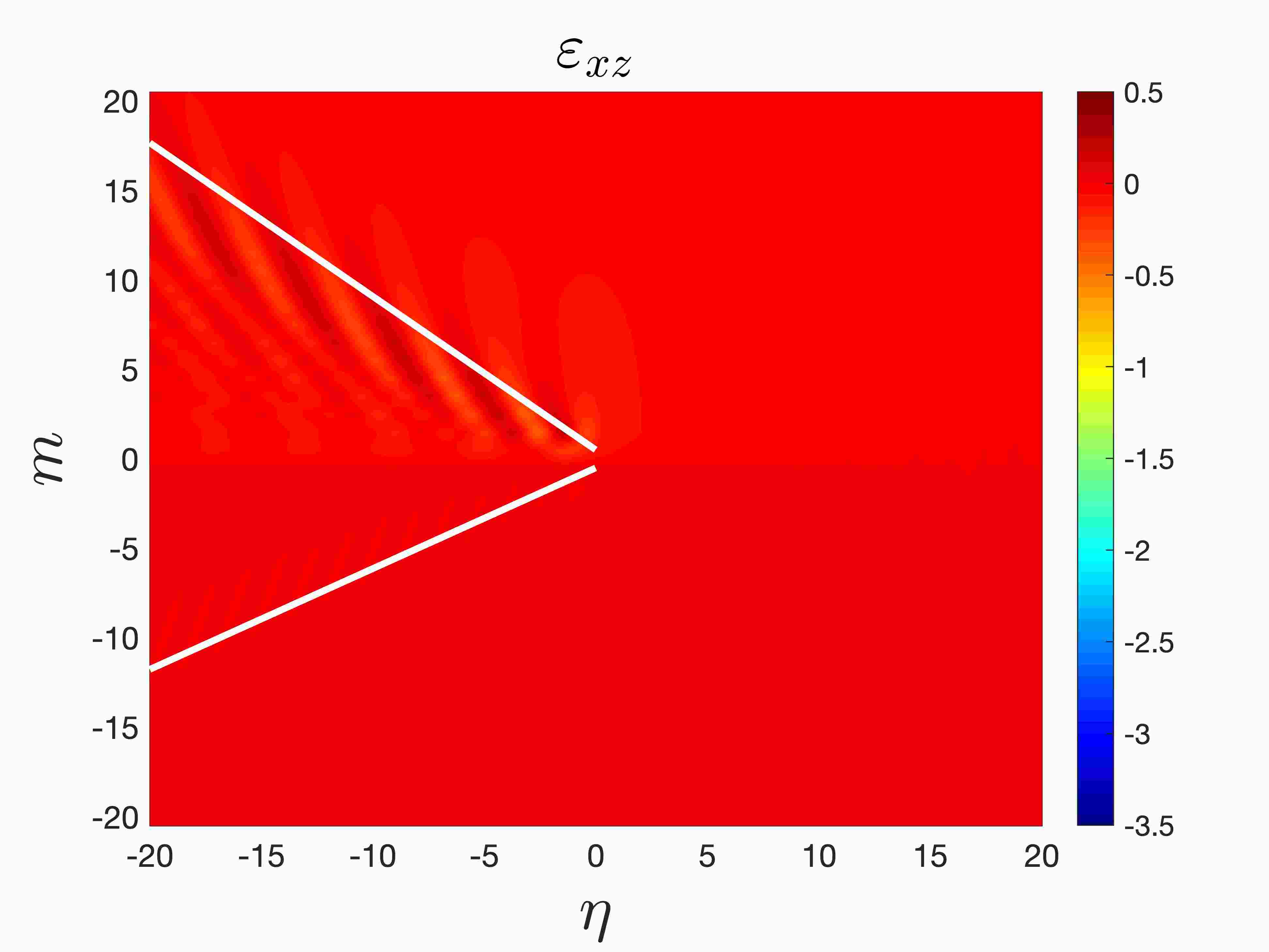
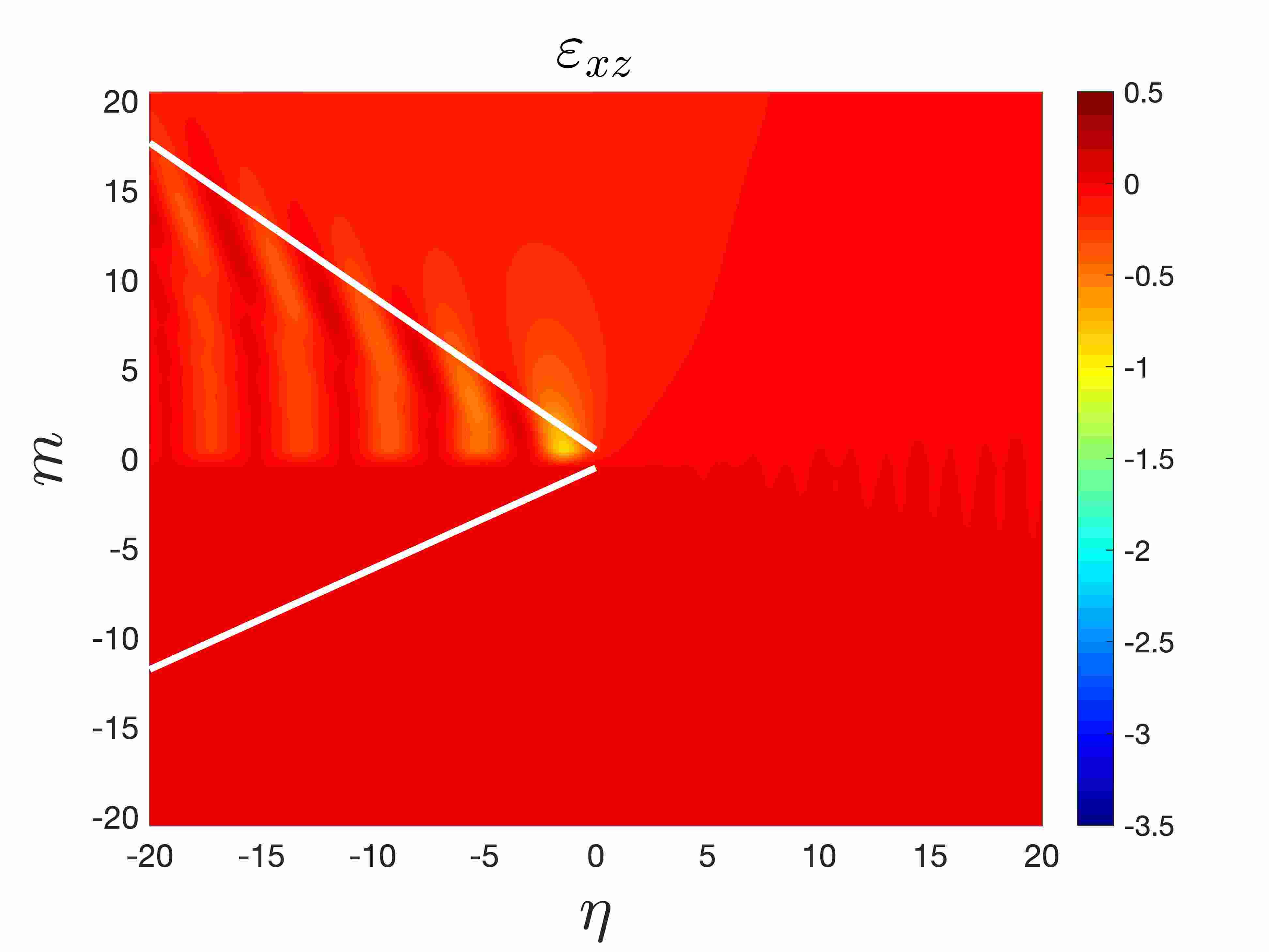
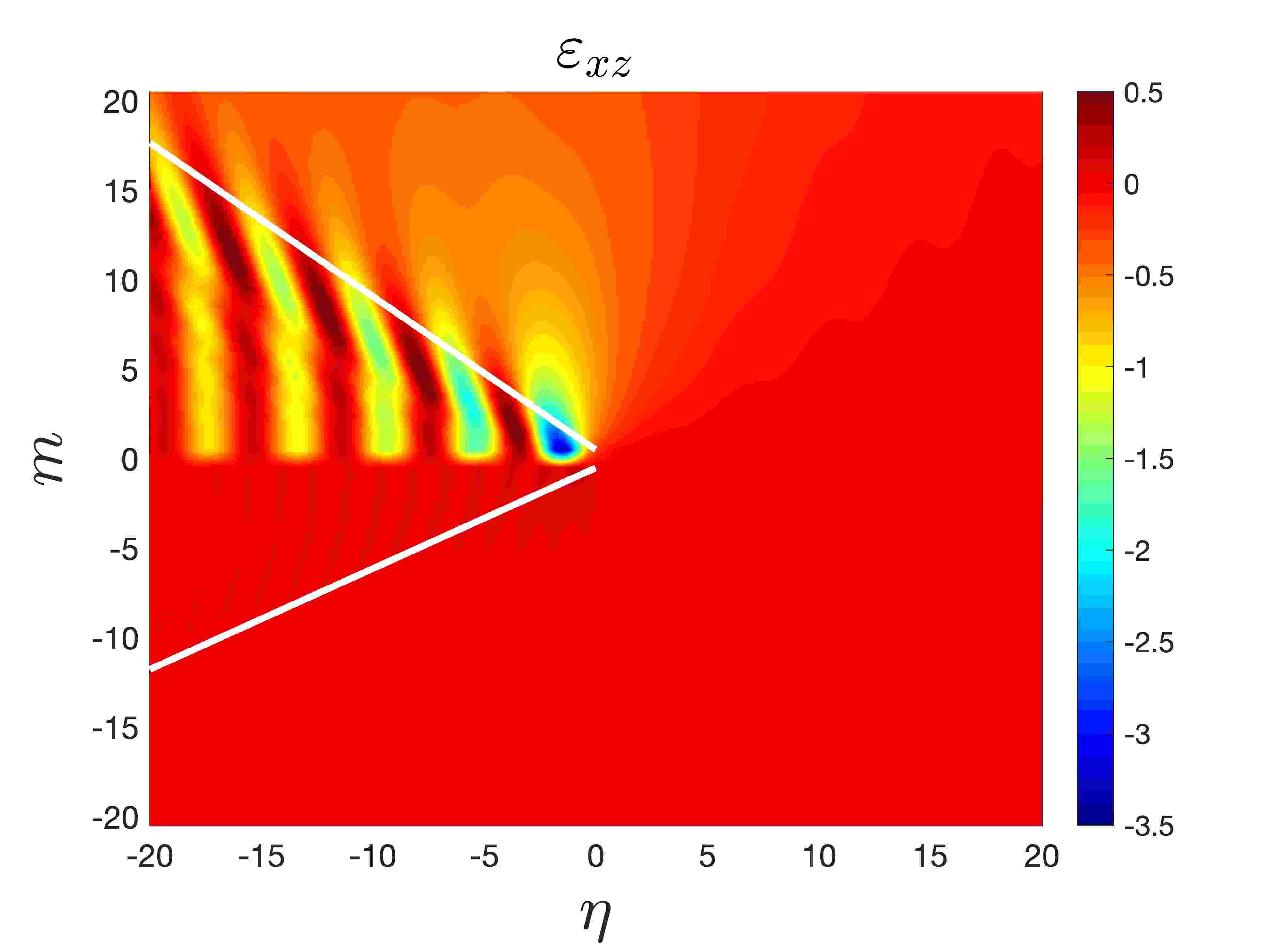
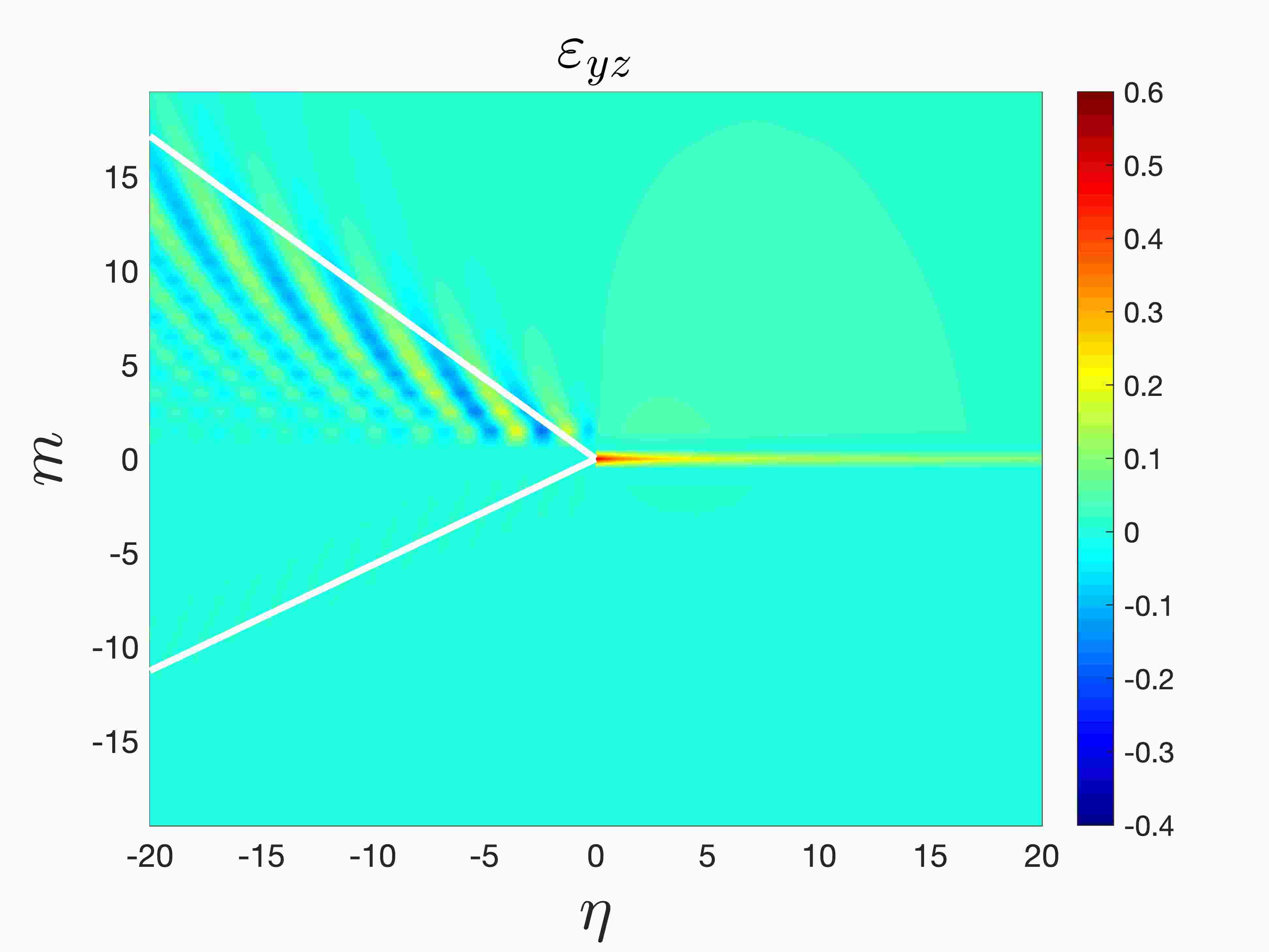
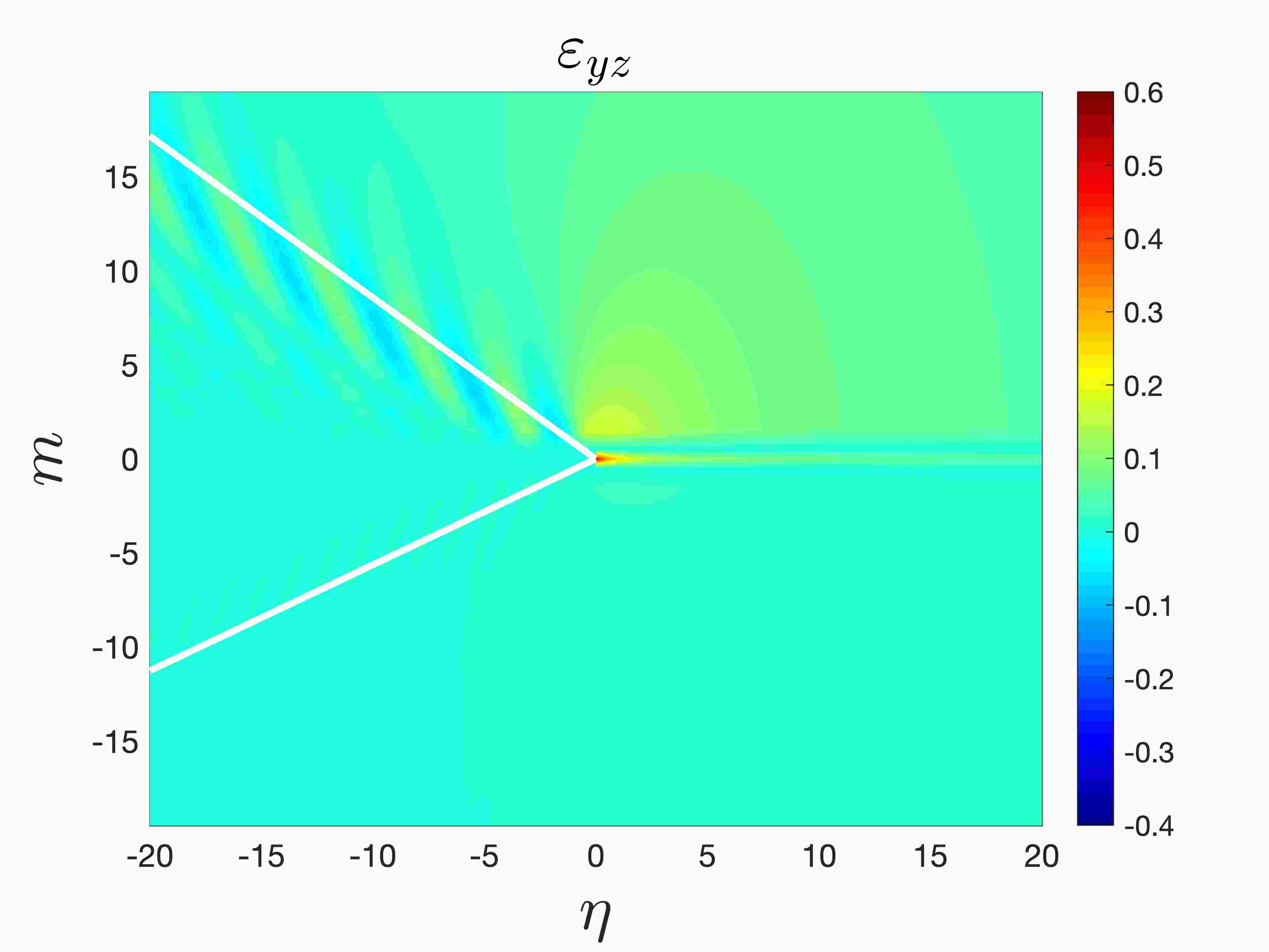
Figures 14(a)–(c) show the resulting displacement plots for the dissimilar lattices for the lowest speed considered. These clearly demonstrate that the softer lattice undergoes larger deformations than the stiffer lattice and again the deformation is no longer symmetrical about the crack path. This is also reflected in the results concerning the strain fields and shown in Figures 14(d)–(f) and (g)–(i), respectively.
These figures show the upper lattice admits a ray along which waves are radiated into the bulk, whereas the lower lattice does not possess such a ray. Indeed, it corresponds to the theoretical findings of Section 4, where functions , are identical only in the case when the upper and lower lattice share the same wave speed.
In addition, Figures 14(d)–(f) and (g)–(i) illustrate the disparity in the micro-structural behaviour of the upper and lower lattice. For instance, Figures 14(e), (f), (h) and (i) show that if the interface is not soft then the upper lattice admits visible wave radiation patterns. In the lower lattice, these effects are much weaker as this medium possesses both a higher density and stiffness than the upper lattice. Vibrations in the upper lattice appear to be confined between the crack and the wave radiation ray as shown in these figures. On the other hand, in the lower lattice the micro-structural deformations are less localised. As before, for softer interfaces the wave radiation effects are less visible and there the macro-scale deformations linked to the propagating crack are the dominant features (see Figures 14(d) and (g)).
Figures 14(g)–(i) also reveal a prominent strain distribution ahead of the crack tip, due to the difference in the displacements in upper and lower lattices. In addition, these figures illustrate that as the interfacial bond stiffness is increased the magnitude of the vibrations distributed along the wave radiation ray in the upper lattice also becomes more significant. Moreover, a concentrated region of high deformation can appear in the softer lattice local to the crack tip as in Section 6.2.
Comparing Figures 15(a)–(c) with Figures 14(a)–(c),we see that when the crack speed is increased the deformations of lattice can increase. Figure 15(a)–(c) provide the displacement fields for the medium and, again for the dissimilar structures considered, the lower lattice does not undergo any significant deformations in comparison with the upper lattice.
Figures 15(d)–(i) illustrate that for a faster crack, the lattice can admit wave radiation rays in both the upper and lower bulk lattices that are not symmetric about the crack line. Figures 15(d)–(f) demonstrate that for higher speeds, micro-structural oscillations in the strains of the lower lattice ahead of the crack tip can be encountered. These oscillations become more prominent with increase of the interfacial bond stiffness. In particular, Figure 15(f) shows there exist visible ripples in the lattice strains localised to the region bounded by the wave radiation rays for , corresponding to the perfect join of the lattices at . Again, having a softer interface suppresses this effect in the lower lattice (see Figures 15(d) and (e)).
Figures 15(g)–(h) show the strains in the upper lattice possess a similar distribution to those presented in Figures 14(g)–(h). The main difference here being that the increase in the crack speed causes the wave radiation effects and the deformations in crack tip neighborhood to be more localised. For the stiffer lattice the distribution of these strains appears to be almost uniform, with increase in the interfacial bond stiffness bringing barely visible effects in terms of wave radiation (see Figure 15(i)).
6.4 Failure mode inducing an interfacial wave
In the previous examples we focused on failure modes where the wave radiation, attributed to the propagation of failure in the lattice, occurred behind the crack tip. It follows from the analysis of Section 3.1, that one can find interfacial wave modes that can be initiated ahead of the crack tip as it propagates (see also Supplementary Material SM.3). Here we consider an example showing an admissible failure mode of this type for a lattice described by the parameters , , , and . In this case, the lattice properties are fully dissimilar and they represent a structure involving an interface joining two different anisotropic lattices having sufficiently softer transverse links in comparison with the interfacial bonds. Additionally, the mass density of the upper lattice is much greater than that of the lower lattice.
Figure 16 shows the dispersion diagram for this case, where in addition to the acoustic curves, both optical curves describing waves in the dissimilar medium are present.

Figure 17 illustrates the behaviour of this lattice as it undergoes steady state failure with a speed below the shear wave speed of the lower lattice half-plane. In Figure 17(a) the function defined in (28) is shown. This function indicates the square root growth of the solution behind the crack tip () that is super-positioned with waves that radiate behind the tip as the crack advances. Here the failure criterion is satisfied at and for , the solution does not possess displacements greater than the critical threshold for failure (indicated by unity in the vertical axis in Figures 17(a) by the dash-dot line). Figure 17(b) shows the magnification of the plot in Figure 17(a), where it is evident that ahead of the crack tip, a wave of constant amplitude is transmitted as the fault propagates. We note the oscillations along the interface induced by this transmitted wave are attributed to the movement of the nodes along the rows as shown in Figure 17(c), which also shows the upper lattice particles along ahead of the crack tip have a significantly smaller displacement amplitude than those along .
As predicted in Section 3 and the Supplementary Material SM.7, the transmitted wave is exponentially localised about and . Far ahead of the crack tip in the lattice, one can expect the transmitted mode to behave as in the case of the free vibration problem for the dissimilar lattice, studied in Section 3. This mode exhibits a strong localisation about the interface is shown in Figure 17(d) and corresponds to the frequency and wavenumber defined by intersection point of the line with the highest optical curve in Figure 16.
The transverse strains in the lattice are shown in Figure 17(e). They reveal that in addition to the transmitted wave ahead of the crack tip, the upper lattice undergoes high deformations both in a region just ahead of the crack tip and behind it, where the lattice is subjected to waves radiated by the progression of the fault. In comparison with the upper lattice behaviour, during the failure process the spatial variation of the deformation in the lower lattice is not as significant. These effects are also present in the plot of the horizontal strains in the lattice, illustrated in Figure 17(f). In both Figure 17(e) and (f), rays corresponding to the directions with the most significant wave radiation are shown. In particular, these examples show the lighter lattice may possess several directions where wave radiation is prominent, whereas in the upper lattice only a single ray is found.
The case considered here was investigated for a high crack speed. As illustrated by the examples in this section, high crack speeds lead to possible scenarios where crack deviation or roughening of the crack surfaces can occur if the integrity of the upper and lower lattices is considered in addition to the integrity of the interfacial bonds. In this case, the solution presented in Figure 17 would be not admissible. We note the occurrence of transmitted modes is most significant when considering low crack velocities, but as we have shown in the above examples, at these velocities the solution constructed is typically not admissible. This may result from the fact that even if the transmitted wave has finite amplitude that does not induce critical strains ahead of the crack, its combination with the effects local to the crack tip may yield a significant crack path displacement rendering the solution not admissible. Hence, this makes the effects of the transmitted failure mode illustrated here difficult to capture without inducing non-steady fracture mechanisms.

7 Conclusions
We have presented the analysis of a discrete dissimilar lattice formed by two contrasting structured media joined by interfacial links that undergo steady fracture. In this problem, the fracture is assumed to be caused by the remote load that allows the solution to recreate the behaviour encountered near the tip of an interfacial crack propagating between two elastic solids, but we note that the formulation developed here allows for general classes of loads to be considered that also embed oscillations.
The problem has been solved via a reduction to a Wiener-Hopf equation through the Fourier transform by taking advantage of the assumption the crack propagates with a uniform speed. The detailed analysis of this functional equation and its solution has been carried out. This has enabled the full characterisation, through a dispersion and asymptotic analysis, of the dynamic processes that can occur during the fracture process. This includes vibrations that excite the lattice microstructure and the global deformation associated with the behaviour of the solution of the continuous problem for a crack propagating in a continuous bi-material.
The study of the wave radiation process due to the propagation of the crack has also been presented and it was shown that there exist crack propagation regimes where vibrations are transmitted and reflected or only reflected from the crack tip. In particular, the energy release ratio, comparing the lattice energy release rate with the global energy release rate, has been used to identify the amount of energy distributed to wave radiation processes. This was also accompanied by the analysis of the influence of the dissimilar lattice parameters on this quantity. Additionally, the solution of the problem has been implemented to determine admissible regimes for steady crack propagation and where the crack will propagate non-uniformly. Several examples have also shown how the admissibility of the steady fracture regimes are affected by the properties of the dissimilar lattice.
Applications of the considered problem include civil engineering, where the control of vibrations of dissimilar frame-like structures is of importance, and advanced material manufacturing, where the customisation of the material properties of structured medium can lead to failure resistant materials for specific configurations.
Acknowledgements: A.P. would like to acknowledge financial support from the European Union’s Seventh Framework Programme FP7/2007-2013/ under REA grant agreement number PCIG13-GA-2013-618375-MeMic. G.M. acknowledges financial support from the ERC Advanced Grant “Instabilities and nonlocal multiscale modelling of materials”: ERC-2013-ADG-340561-INSTABILITIES. G.M, also thanks M. Kachanov for his illuminating comments during G.M.’s visit to Nizhny Novgorod Technical University supported by the project no. 14.Z50.31.0036 from the Ministry of Education and Science of the Russian Federation. He is also thankful to Royal Society for the Wolfson Research Merit Award. M.J.N. gratefully acknowledges the support of the EU H2020 grant MSCA-IF-2016-747334-CAT-FFLAP. G.M and M.N. also thank the Simons Foundation for their financial support. The authors would like to thank the Isaac Newton Institute for Mathematical Sciences, Cambridge, for the support and hospitality during the programme “Bringing pure and applied analysis together via the Wiener-Hopf technique, its generalisations and applications”, where some work on this paper was undertaken with the financial support through EPSRC grant no EP/R014604/1.
Appendix: Parameters governing the appearance of interfacial waves
Here, in accordance with the description of the dispersion features in Section 3.1, we detail when the optical curves , can exist. We assume the parameters characterising the upper and lower lattice half-planes are given apriori and determine intervals for the crack bond stiffness for when the optical curves appear. To enable this, we define the following four critical values for the crack bond stiffness :
| (A.1) | |||
| (A.2) | |||
| (A.3) |
and
| (A.4) |
We recall that the presence of the optical branches implies there exists frequency ranges where the interfacial waves propagate along the line inhomogeneity in the lattice and are exponentially localised about this defect. In Tables 1 and 2 we report the results concerning the intervals of where the dissimilar lattice will support high frequency interfacial waves based on the choices of or , respectively, and the parameters , and (see the first columns of these tables for bounds on these parameters). These waves are connected with the optical curve that can be either continuous or piecewise defined and for these scenarios the intervals for are shown in the first and second columns, respectively, of Tables 1 and 2.
The low frequency interfacial waves are associated with the optical branch , which is always piecewise defined. The conditions for the appearance of this curve are shown in Table 3.
| Upper and lower lattice parameters | Continuous | Piecewise defined |
|---|---|---|
| , | ||
| Upper and Lower lattice parameters | Continuous | Piecewise defined |
|---|---|---|
| , | ||
| Upper and Lower lattice parameters | |
|---|---|
References
- Bouchbinder et al. (2010) Bouchbinder, E., Fineberg, J. and Marder, M. (2010): Dynamics of simple cracks, Annual Review of Condensed Matter Physics 1, 375–395.
- Cox et al. (2005) Cox, B.N., Gao, H., Gross, D. and Rittel, D. (2005): Modern topics and challenges in dynamic fracture, Journal of the Mechanics and Physics of Solids 53, 565–596.
- Rosakis (2002) A. J. Rosakis (2002): Intersonic shear cracks and fault ruptures, Advances in Physics 51, no. 4, 1189–1257.
- Wang, Rubin and Ampuero (2014) E. Wang, A. Rubin and J. P. Ampuero, (2014): Compound earthquakes on a bimaterial interface and implications for rupture mechanics, Geophys. J. Int. 197, 1138–1153.
- Brietzke, Cochard and Igel (2009) G. B. Brietzke, A. Cochard and H. Igel (2009): Importance of bimaterial interfaces for earthquake dynamics and string ground motion, Geophys. J. Int. 178, 921–938.
- Guo et al. (2015) L. Guo, T. Kitamura, Y. Yan, T. Sumigawa and K. Huang (2015): Fracture mechanics investigation on crack propagation in the nano-multilayered materials, Int. J. Solids Struct. 64–65, 208–220.
- Beuhler (2008) M. J. Buehler, (2008): Atomistic Modeling of Materials Failure, Springer.
- Beuhler and Gao (2004) M.J. Buehler and H. Gao (2004): A mother-daughter-grandaughter mechanism of shear dominated intersonic crack motion along interfaces of dissimilar materials, Journal of the Chinese Institute of Engineers 27, no. 6, 763–769.
- Buehler and Gao (2006) M.J. Buehler and H. Gao (2006): Modeling dynamic fracture using large-scale atomistic simulations, Dynamic Fracture Mechanics, 1–68.
- Gall et al. (2000) K. Gall, M. F. Horstemeyer, M.V. Schilfgaarde and M. I. Baskes (2000): Atomistic simulations on the tensile debonding of an aluminium-silicon interface, Journal of the Mechanics and Physics of Solids 48, 2183–2212.
- A.H. England (1965) A.H. England, (1965): A crack between dissimilar media, J. of Appl. Mech. 32, no.2, 400–402.
- Rice and Sih (1965) J.R. Rice and G.C. Sih (1965): Plane problems of cracks in dissimilar media, J. of Appl. Mech. 32, no.2, 418–423.
- Rice (1988) J.R. Rice, (1988): Elastic Fracture Mechanics concepts for interfacial cracks. J. Appl. Mech. 55, no. 1, 98–103.
- Williams (1959) M. L. Williams, (1959): The stresses around a fault of crack in dissimilar media, Bulletin of the Seismological Society of America 49, no. 2, 199–204.
- Yang, Suo and Shih (1991) W. Yang, Z. Suo, C.F. Shih (1991): Mechanics of dynamic debonding, Proc. R. Soc. Lond. A, 433, 679–607.
- Liu, Huang and Rosakis (1995) C. Liu, Y. Huang and A. J. Rosakis, (1995): Shear dominated transonic interfacial crack growth in a bimaterial–II. Asymptotic fields and favorable velocity regimes, J. Mech. Phys. Solids 43, no. 2, 189–206.
- Yu and Yang (1994) H. Yu and W. Yang (1994): Mechanics of transonic debonding of a bimaterial interface: the antiplane shear case, J. Mech. phys. Solids 42, no. 11, 1789–1802.
- Huang, Liu and Rosakis (1996) Y. Huang, C. Liu and A. J. Rosakis (1996): Transonic crack growth along a bimaterial interface: An investigation of the asymptotic structure of near tip fields, Int. J. Solids Structures 33, no. 18, 2625–2645.
- Yu and Suo (2000) H. H. Yu and Z. Suo (2000): Intersonic crack growth on an interface, Proc. R. Soc. Lond A 456, 223–246.
- Willis (1971) Willis, J.R. (1971): Fracture mechanics of interfacial cracks. J Mech Phys Solids 19: 353–368.
- Liu, Lambros and Rosakis (1993) C. Liu, J. Lambros and A.J. Rosakis (1993): Highly transient elastocdynamic crack growth in a bimaterial interface: higher order asymptotic analysis and optical experiments, J. Mech. Phys. Solids 41, no. 12, 1887–1954.
- Rosakis et al. (1998) A.J. Rosakis, O.S. Samudrala, R. P. Singh and A. Shukla (1998): Intersonic crack propagation in bimaterial systems, J. Mech. Phys. Solids 46, no. 10, 1789–1813.
- Chen and Gao (2010) S. Chen and H. Gao, (2010): Dynamic behaviours of mode III interfacial crack under constant loading rate, Continuum Mech. Thermodyn. 22, 515–530.
- Ing and Ma (1997) Y. S. Ing and C. C. Ma (1997): Dynamic analysis of a propagating antiplane interface crack, Journal of Engineering Mechanics 123, no. 8., 783–791.
- Lambros and Rosakis (1995) J. Lambros and A. J. Rosakis (1995), Development of a dynamic decohesion criterion for subsonic fracture of the interface between two dissimilar materials, Proc. R. Soc. Lond. A, 451, 711–736.
- Kiley and Tippur (2005) R. Kiley and H.V. Tippur (2005): Dynamic crack growth in particulate bimaterials having discrete and diffuse interfaces: Role of microstructure, Engineering Fracture Mechanics 72, 2721–2743.
- Djoković, et al. (2014) J. M. Djoković, R. R. Nikolić, J. Vičan and D. Djenadić (2014): Dynamic crack growth of an interfacial crack between two anisotropic materials, FME tTransactions 42, no. 3, 229–236.
- Clements (1971) D. L. Clements (1971): A crack between dissimilar anisotropic media, Int. J. Engng Sci. 9, 257–265.
- Suo (1990) Z. Suo, (1990): Singularities, Interfaces and cracks in dissimilar anisotropic media, Proc. R. Soc. Lond. A 427, 331–358.
- Piccolroaz, Mishuris and Radi (2012) A. Piccolroaz, G. Mishuris and E. Radi (2012): Mode III interfacial crack in the presence of couple stress elastic materials, Engineering Fracture Mechanics 80, 60–71.
- Huang, Guo and Yu (2018) K. Huang, L. Guo, H. Yu, (2018): Investigations on mixed-mode dynamic stress intensity factors of an interface crack in bimaterials with an inclusion. Composite Structures 202, 491–499.
- Piccolroaz, Mishuris and Movchan (2010) Piccolroaz, A., Mishuris, G., Movchan, A.B. (2010): Perturbation of Mode-III problem for semi infinite crack in bi-material plane. International Journal of Solids and Structures 49, no.1, 244-255
- Birman (2018) V. Birman (2018): Control of fracture at the interface of dissimilar materials using randomly oriented inclusions and networks, Int. J. Eng. Sci. 130, 157–174.
- Beom and Jang (2012) H.G. Beom and H.S. Jang (2012): Interfacial wedge cracks in dissimilar anisotropic materials under antiplane shear, Int. J. Eng. Sci. 56, 49–62.
- Ma, Su and Feng (2018) P. Ma, R.K.L. Su and W.J. Feng (2018): Singularity of subsonic and transonic crack propagations along interfaces of magnetoelectroelastic bimaterials, Int. J. Sci. Eng 129, 21–33.
- Fineberg and Marder (1999) Fineberg, J. and Marder, M. (1999): Instabilities in dynamic fracture, Physics Reports 313, 1-108.
- Marder (2005) Marder, M. (2005): Influence of microstructure on dynamic fractures, International Conference on Fracture.
- Marder (2004) Marder, M. (2004): Effects of atoms on brittle fracture, International Journal of Fracture 130, 516–555.
- Berger et al. (2011) Berger, J., Mercer, C., Meeking, R.M. and Evans, A.G. (2011): The design of bonded bimaterial lattices that combine low thermal expansion with high stiffness, J. Am. Ceram. Soc. 94, S42–S54.
- Slepyan and Troyankina (1983) Slepyan L.I. and Troyankina L.V. (1983): On the Theory of Crack Grows Under Cyclic Loads. Mechanics of Solids 18: 101-124.
- Slepyan (2001a) Slepyan, L.I. (2001): Feeding and dissipative waves in fracture and phase transition I. Some 1D structures and a square-cell lattice, Journal of the Mechanics and Physics of Solids 49, 469–511.
- Slepyan (2002) Slepyan, L.I. (2002): Models and Phenomena in Fracture Mechanics, Foundations of Engineering Mechanics, Springer.
- Slepyan (2001b) Slepyan, L.I. (2001): Feeding and dissipative waves in fracture and phase transition II. Phase-transition waves, Journal of the Mechanics and Physics of Solids 49, 513–550.
- Slepyan (2001c) Slepyan, L.I. (2001): Feeding and dissipative waves in fracture and phase transition. III. Triangular-cell lattice, Journal of the Mechanics and Physics of Solids 49, 2839–2875.
- Mishuris, Movchan and Slepyan (2007) Mishuris, G.S., Movchan, A.B. and Slepyan, L.I., (2007): Waves and fracture in an inhomogeneous lattice structure, Waves in Random and Complex Media 17, no. 4, 409–428.
- Nieves et al. (2013) Nieves, M.J., Movchan, A.B., Jones, I.S., Mishuris, G.S., (2013): Propagation of Slepyan’s crack in a non-uniform elastic lattice, Journal of the Mechanics and Physics of Solids 61, no 6, 1464–1488.
- Mishuris, Movchan and Slepyan (2009) Mishuris, G.S., Movchan, A.B. and Slepyan, L.I., (2009): Localised knife waves in structured in a structured interface, Journal of the Mechanics and Physics of Solids 57, 1958–1979.
- Slepyan, Movchan and Mishuris (2010) Slepyan, L.I., Movchan, A.B., Mishuris, G.S., (2010): Crack in a lattice waveguide, International Journal of Fracture 162, 91–106.
- Gorbushin and Mishuris (2018) Gorbushin, N. and Mishuris, G., (2018): Dynamic fracture of a discrete media under moving, International Journal of Solids and Structures 130–131, 280–295.
- Slepyan and Ayzenberg-Stepanenko (2004) Slepyan, L.I. and Ayzenberg-Stepanenko, M.V. (2004): Localized transition waves in bistable-bond lattices, Journal of the Mechanics and Physics of Solids 52, 1447-1479.
- Mishuris, Movchan and Slepyan (2008a) Mishuris, G.S., Movchan, A.B., Slepyan, L.I., (2008): Dynamical extraction of a single chain from a discrete lattice, Journal of the Mechanics and Physics of Solids 56, 487–495.
- Mishuris, Movchan and Slepyan (2008b) Mishuris, G.S., Movchan, A.B., Slepyan, L.I., (2008): Dynamics of a bridged crack in a discrete lattice, Quarterly Journal of Mechanics and Applied Mathematics 61, no.2, 151–159.
- Gorbushin et al. (2017) Gorbushin, N., Vitucci, G., Mishuris, G. and Volkov, G. (2017): Influence of fracture criteria on dynamic fracture in discrete chain, International Journal of Fracture 209, nos. 1–2, 131–142.
- Morini et al. (2013) L. Morini, A. Piccolroaz, G. Mishuris and E. Radi (2013): On fracture for dynamic crack propagation in elastic materials with couple stresses, Int. J. Eng. Sci. 71, 45–61.
- Cherkaev and Leelavanichkul (2012) A. Cherkaev and S. Leelavanichkul (2012): Approached to description of damageable lattices dynamics, Int. J. Eng. Sci. 58, 35–44.
- Osharovich and Ayzenberg-Stepanenko (2012) G.G. Osharovich, M.V. Ayzenberg-Stepanenko (2012): Wave localization in stratified square-cell lattices: The antiplane problem, Journal of Sound and Vibration 331, no. 6, 1378–1397.
- Colquitt et al. (2012) D.J. Colquitt, M.J. Nieves, I.S. Jones, N.V. Movchan, A.B. Movchan (2012): Localisation for a line defect in an infinite square lattice. Proc. R. Soc. A 469: 20120579.
- Makwana and Craster (2018a) M.P. Makwana and R.V. Craster (2018): Geometrically navigating topological platonic modes around gentle and sharp bends, ArXiv, arXiv:1806.03630.
- Makwana and Craster (2018b) M.P. Makwana and R.V. Craster (2018): Designing multi-directional energy-splitters and topological valley supernetworks, ArXiv, arXiv:1806.03631.
- Makwana, Craster and Guenneau (2019) M. Makwana, R. Craster and S. Guenneau (2019): Topological beam-splitting in photonic crystals, Opt. Express 27, no. 11 16088-16102.
- Zheng et al. (2018) L.-Y. Zheng, G. Teocharis, V. Tournat and V. Gusev (2018): Quasi-topological rotational waves in mechanical granular graphene, Phys. Rev. B 97, 060101(R).
- Garau et al. (2018) M. Garau, G. Carta, M.J. Nieves, I.S. Jones, N.V. Movchan and A.B. Movchan (2018): Interfacial waveforms in chiral lattices with gyroscopic spinners, Proc. Roy. Soc. A. 474, 20180132.
- Marder and Gross (1995) Marder, M. and Gross, S. (1995): Origin of crack tip instabilities, Journal of the Mechanics and Physics of Solids 43, no. 1, 1–48.
- Gorbushin and Mishuris (2017) Gorbushin, N. and Mishuris, G. (2017): On admissible steady-state regimes of crack propagation in a square-cell lattice, ArXiv preprint, arXiv:1701.04818v3.
- Gorbushin and Mishuris (2016) Gorbushin, N. and Mishuris, G., (2016): Analysis of dynamic failure of the discrete chain structure with non-local interactions, ArXiv preprint, arXiv:1512.01540v2.
- Slepyan (2005) Slepyan, L.I. (2005): Crack in a material-bond lattice, Journal of the Mechanics and Physics of Solids 53, no. 6, 1295–1313.
- Brun, Movchan and Slepyan (2013) Brun, M., Movchan, A.B. and Slepyan, L.I., (2013): Transition wave in a supported heavy beam, Journal of the Mechanics and Physics of Solids 61, no. 10, 2067–2085.
- Brun, Movchan and Slepyan (2013) Brun, M., Giaccu, G.F., Movchan, A.B., and Slepyan, L. I., (2014): Transition wave in the collapse of the San Saba Bridge, Front. Mater. 1:12. doi: 10.3389/fmats.2014.00012.
- Nieves, Mishuris and Slepyan (2016) Nieves, M.J., Mishuris, G.S., Slepyan, L.I., (2016): Analysis of dynamic damage propagation in discrete beam structures, International Journal of Solids and Structures 97-98, 699-713.
- Nieves, Mishuris and Slepyan (2017) Nieves, M.J., Mishuris, G.S., Slepyan, L.I., (2017): Transient wave in a transformable periodic flexural structure, International Journal of Solids and Structures 112, 185–208.
- Tewary and Thompson (1992) Tewary, V.K. and Thompson, R. (1992): Lattice statics of interfaces and interfacial cracks in bimaterial solids, J. Mater. Res. 7, no. 4, 1018–1028.
- Berinskii and Slepyan (2017) I.E. Berinskii and L.I. Slepyan (2017), How a dissimilar-chain system is splitting: Quasi-static, subsonic and supersonic regimes, Journal of the Mechanics and Physics of Solids 107, 509–524.
- Gorbushin and Mishuris (2017) N. Gorbushin and G Mishuris (2019): Dynamic fracture of a dissimilar chain. Philosophical Transactions of the Royal Society A, 377(2156), 20190103.
- Rogosin and Mishuris (2016) S. Rogosin and G. Mishuris (2016): Constructive methods for factorization of matrix-functions, IMA Journal of Applied Mathematics 81, no. 2, 365–391.
- Stoneley (1926) Stoneley, R. (1926): Elastic waves at the surface of separation of two solids, Proc. R. Soc. Lond. A. 106, no. 738, 416–428.
- Barnett et al. (1985) Barnett, D.M., Lothe, J., Gavazza, S.D. and Musgrave, M.J.P. (1985): Considerations of the existence of interfacial (Stoneley) in bonded anisotrpic elastic half-spaces. Proc. R. Soc. Lond. A. 402, 153–166.
- Garau, Nieves and Jones (2019) M. Garau, M.J. Nieves, I.S. Jones (2019): Alternating strain regimes for failure propagation in flexural systems, Quart. J. Mech. Appl. Math. 72, no. 3, 305?339.
- Slepyan (2010) L.I. Slepyan, (2010): Wave radiation in lattice fracture, Acoustical Physics 56, no. 6, 962–971.
- Suo (1990) Z. Suo (1990): Singularities, interfaces and cracks in dissimilar anisotropic media Proc. R. Soc. Lond. A 427, 331–358.
- Mishuris, Movchan and Movchan (2006) G.S. Mishuris, N.V. Movchan, A.B. Movchan (2006): Steady-state motion of a mode-III crack on imperfect interfaces, Q. J. Mech. Appl. Math. 59, no. 4 487–516.
Supplementary Material
SM.1 Derivation of the transformed equations and the matrix Wiener-Hopf problem
By introducing the continuous variable and (16), the dimensionless equations of motion (10)–(13) are updated to
| (SM.1) |
for ,
| (SM.2) |
for , whereas along the lines containing the propagating defect we have
| (SM.3) |
and
| (SM.4) |
Here, the prime in the above equations represents differentiation with respect to .
Let us first consider (SM.1) and (SM.2). The application of Fourier transform with respect to (see (20)) and use of the following formulae
and
leads to
| (SM.5) |
for and
| (SM.6) |
for . The preceding equations can be then rearranged to give (19).
Taking advantage from the fact that the coefficients in the system of linear equations (19) do not depend on the value of and , we seek the solutions in the form (24) where the exponents are independent of . For a physically acceptable solution we also impose (27).
Substituting (24) into (19), leads to a quadratic equation to determine the functions :
| (SM.7) |
with defined in (26). Note that from the preceding equation, the second relation in (26) follows immediately. The equations in (SM.7) deliver two solutions for , and we choose the branch to satisfy the requirement (27). Thus, we have
and if we may write as in (25).
Next we apply the Fourier transform defined in (20) to (SM.3) and (SM.4). We obtain
| (SM.8) |
and
| (SM.9) |
We then use the solution for the lattice half-plane problems defined by (24). Equations (32) then follow from this by using (31), which represents the Fourier transform of the function corresponding to the crack opening for and elongation of the interfacial bonds for . Moreover, using (24) and invoking the additive splits (22), in (SM.8) and (SM.9) we can gather terms corresponding to “” and “” to retrieve (33) and (34).
SM.2 Eigenmodes for lattice problems connected with the failure of the dissimiliar structure
Here we describe the method for constructing the eigenmodes for the problems linked to the propagation waves in the lattice half-planes with free boundaries and in the dissimilar structured medium, on which the computations in Section 3 are based.
Eigenmodes of the semi-infinite lattices with free boundaries. The branches and in (21) are connected with the vibration modes of the separated semi-infinite upper or lower lattices, respectively. Along the branch () the associated eigenmode in the upper (lower) lattice half-plane has constant amplitude in the direction perpendicular to boundary and oscillates in the direction parallel to the boundary. If , both half-planes produce a different dynamic response provided . For a given frequency , the eigenmodes can be determined from (10) and (13), assuming that
| (SM.10) |
where the amplitudes and are sought in the form
| (SM.11) |
These assumptions lead to the equations
| (SM.12) |
which are satisfied by and , respectively. Note in this case, and are independent.
Eigenmodes along the high frequency optical curves. For the dissimilar lattice with an interface, the eigenmodes can be computed using the governing equations (10)–(13) (assuming ), with (SM.10) and (SM.11). They lead to the following homogeneous system that couples the amplitudes and :
| (SM.13) |
where the coefficient matrix is degenerate along the curves , , discussed in Section 3.
SM.3 Dynamic features of the dissimilar lattice undergoing steady-state fracture
To determine the behaviour of the dissimilar lattice undergoing fracture, we use the dispersion properties of the two lattices considered in Section 3. The associated dispersion curves define waves incident on and radiated from the crack front during the steady failure process. The waves are identified by considering the line on the dispersion diagram as in the work of Slepyan (2002), with being the crack speed satisfying (15).
Incident and radiated waves propagating behind the crack front. In the subsonic regime, the kernel function has a singular point at zero associated with the intersection of the acoustic branches , with at the origin on the dispersion diagram. It corresponds to the continuum or long wavelength limit of the lattice. In fact, as discussed in the main text, this singular point is connected with the application of a remote load that leads to a solution corresponding to the field local to the crack tip of a dynamic interfacial defect propagating through a dissimilar continuous elastic medium.
Additionally, owing to the intersections of the line with , the function has one, three or more pairs of singular points at , , , where , , is dependent on the crack speed. As an example, we refer to Figure SM.2, where it can be seen for the lines with , 0.15 and 0.4 we have and 0, respectively.
Similarly, analysing the intersections of with on the dispersion diagram, can have additional singular points at , , , , . Once more, is dependent on the crack speed. The example presented in Figure SM.2 shows for , 0.15 and 0.4 that , respectively.

We also compare the crack speed (slope of ) with the group velocity at each intersection point and note that for intersection points with the wave numbers:
-
1.
and , with , , the group velocity . These wave numbers are connected with waves located at that appear as the crack tip advances and are radiated behind it.
-
2.
and , with , , the group velocity . These wave numbers define waves incident on the crack front that propagate in the region . In this article, we do not consider loading that produces such a dynamic response and these wave numbers can be neglected.
In particular the singular wave numbers of identified here define branch points of this function.
Transmitted waves ahead of the crack front. Now we describe the waves that can appear ahead of the crack front during the fracture process. These waves are connected with the intersection points of the line with the optical branches , . As mentioned in the previous section, these curves may not exist and their appearance is related to a specific choice of the lattice material parameters. The analysis is separated into the following scenarios:

(a) (b)
-
Case 1: If (42) does not hold, then the optical branches , do not exist. In such a case, only evanescent waves can propagate ahead of the crack front. These are associated with the zero points of , located in the lower half of the complex plane defined by having non-negligible imaginary parts. In this scenario the dispersion diagram is as reported in Figure SM.2.
-
Case 2: When the high frequency optical branch exists and this is either a piecewise defined curve or a continuous curve. Let the pairs of wave numbers associated with the intersection points of with the line be , , , , . They represent zero points of . Here, if is piecewise defined, the number of pairs can be even or odd depending on . Figure SM.3(a) shows several examples for this configuration, where and for and and , respectively. In the situation when is continuous, is always odd as illustrated in Figure SM.3(b).
-
Case 3: Additionally to Case 2, if one of the conditions (44) holds, then the low frequency optical branch may also appear (and this depends on the value of not present in (44)). This curve is always piecewise defined as discussed in the main text. Let the pairs of wave numbers associated with the intersection points of with the line be , , , , . As a result of being always piecewise defined, the integer can be either even or odd depending on the crack speed. Figure SM.4 demonstrates this, where for and 0.05 the number of pairs of zero points of are and 2, respectively.

We can again compare the slope of the line with the group velocity of the optical branches at the intersection points identified in Cases 2 and 3. Then for the intersection points with the wave numbers:
- 1.
- 2.
The above information concerning the group velocity at the intersection points is used in Section 3.2 onwards in the tracing the form of the waves in the lattice. Indeed, it allows us to determine the location of the wave numbers in the complex plane defined by , prior to taking the limit (23). This concludes the analysis of dispersive properties for the system undergoing failure.
SM.4 Derivation of asymptotes for
Here we derive the asymptotic behaviour of the function (see (28)) in the vicinity of the crack tip. We consult its Fourier transform , which owing to (60) takes the equivalent form
| (SM.16) |
where (49) and (50) show that for small wave numbers
| (SM.17) |
with is defined in (71) and is another constant that we do not determine here. with being the constant in (71). Using (55) we can also obtain the asymptote
| (SM.18) |
where is defined in (71). Note that (47), (48) and (54) provide the following asymptote for large wave numbers:
where is the constant defined in (54).
Let denote a “+” function behaving at infinity and near zero in the following manner
| (SM.19) |
and
| (SM.20) |
Further, using (59), with (63), let take the form
| (SM.21) |
Now from this we have
| (SM.22) |
Here, the last term brackets is a bounded function near zero and is as . Additionally, the Cauchy split has been employed to represent this term as the sum of a “+” and a “” function. As a result, we can obtain as
Thus, the asymptote of the function , using (61), (66), (SM.19) and (SM.20) near the crack tip is
| (SM.23) |
with
and far away ahead of the crack tip we have (69), owing to (SM.18) and (SM.19), whereas in the far-field behind the crack tip we receive and (70) using (66).
SM.5 Derivation of the far-field behaviour in the dissimilar lattice undergoing fracture
To estimate the asymptotics of and when we need to consider their Fourier transforms and , given in (24), when . First, we consider the solutions (64). The function can be written as in (SM.21). Owing to (SM.17), (55) and (49) it can be shown (66) holds.
Using (28), (30), (31) and (66), the Fourier transforms and behave as follows when :
| (SM.25) |
The displacements of the remaining layers are found through (24). The factors contained there possess the following asymptotic behaviour:
| (SM.26) |
where constants are
| (SM.27) |
This gives the following leading asymptotic terms of and when :
| (SM.28) |
and
| (SM.29) |
To obtain the far-field asymptotes, we need to calculate the inverse Fourier transforms of these leading terms. We concentrate on as the derivation involving is essentially the same up to constants. We need to calculate:
| (SM.30) |
First, we can take where is some constant and we have
| (SM.31) |
There are two possible cases: and . Moreover, the integrand has branch cuts resulting from the terms contained between the points to , respectively. When we make a contour defined for which runs along the real line, a semi-circle with a sufficiently large radius and the branch cut from to . Allowing the radius of the semi-circle to tend to infinity and taking we reduce the integration from the real line to the integration along the branch cuts with respect to due to Jordan’s lemma of the complex analysis. We have on the right side of the branch cut for which whereas on its left side where . Therefore, we get:
| (SM.32) | |||||
As the last two terms on the right-hand side are complex conjugate to each other, this is equal to
where a change of variable was made in moving to the last equality. After computing the standard integral in the right-hand side we have this is equal to
Thus, we have shown that
| (SM.33) | |||||
For , we have to handle the singular branch point of the kernel in (SM.31) at . We first represent the original integral in the following way:
| (SM.34) |
We construct a similar contour to as before but only in the upper half-plane with the branch cut of running from to . With the same arguments the integration can be calculated along the branch cuts through the change of variables . On the right side of the cut with we have , whereas on the left side of the cut when we have . After integration by parts, the second integral in (SM.34) gives:
| (SM.35) |
Next, repeating similar steps to as before, the above described contour integration in allows us to write:
| (SM.36) | |||||
Next we concentrate on the evaluation of the first integral in (SM.34). Owing to a change variable this becomes:
| (SM.37) | |||||
where again as the terms in the above right-hand side are complex conjugate to each other, we combine them to obtain the integral
Introducing next a change of variable then leads to
that can be evaluated to give
| (SM.38) | |||||
where is the inverse cotangent function. We recall the following properties:
| (SM.39) |
and by combining this with (SM.38) and (SM.34)–(SM.36), we obtain:
| (SM.40) |
which is the same result as for . This and the result (SM.33) with (SM.30) and (SM.31) show that the asymptotic behaviour for large or of is
| (SM.41) |
If we then make the substitution and , we can obtain (77) for . In a similar way to as discussed here, one can show that for large or that
| (SM.42) |
from which (78) follows.
SM.6 Wave radiation segments
Let , denote the zeros of the function and , be the zeros of . Here and are dependent on the crack speed. The wave numbers , correspond to intersection points of the line with
| (SM.43) |
on the dispersion diagram. On the other hand, , represent the wave numbers where the expression and
| (SM.44) |
are equal.
Let and . We define the sets as in (76) and
Here, , are radiation or -segments (see Slepyan (2010)), that define principal directions of the lattice along which waves can be radiated.

(a) (b)
Inside the argument of is negative. Note for , in (25) is complex and can be written as
| (SM.45) |
Outside of the sets , we have , . We use the above facts to determine the far-field behaviour of the lattice displacements through the inverse Fourier transform.
The behaviour of , is demonstrated for a representative example in Figure SM.5. The top panels of Figure SM.5 show the curves of and , , along with the line for a given crack speed . In the bottom panel of Figure SM.5(a), the behaviour of and is shown. The argument of is non-uniform for , where , and has several stationary points. Furthermore, inside . For , with the over line indicating the closure of this set, takes its values on the interval . Similar comments are also valid for , where for we have .
Additionally, in the example of Figure SM.5(a), and the interval is indicated. For Figure SM.5(b), and the interval is also shown. In these intervals, the bottom panels of Figure SM.5 show the arguments of , can oscillate. In particular, Figure SM.5(a) shows has an inflection point, whereas in Figure SM.5(b), the function has several inflection points.
Wave radiation in the lattice bulk
Here, we discuss how the information about -segments is used to determine the propagation direction of slowly decreasing waves in the lattice. As shown above, there may exist several stationary points of the function inside the set , . Moreover, there can exist inflection points of in the radiation segment , . In association with the inflection points of , , we define the sets
and
for , (see (SM.45)). According to Section 4.2, the third integral in the right-hand side of (75) can be used to find the rays in the lattice where wave radiation created by the propagating crack is the most significant. This term leads to the following contribution to the lattice solution , :
| (SM.46) |
where
Note for , using (SM.45) we have . The sets then define preferential directions relative propagating crack tip, where wave radiation amplitude is most significant in the limit . Indeed, we use to define lines in the upper and lower lattice half-planes in the form
| (SM.47) |
along which the phase in (SM.46) has a stationary point, i.e. . As the cardinality of may exceed one, several lines of this type may exist. If , then (SM.47) represents a line emanating from the crack tip located in the upper half space at . For , these lines are located at .
Then, employing a stationary phase argument as adopted by Slepyan (2010), one determines an asymptote for the function as that reveals along the lines (SM.47) the term has the order . A similar approach also shows that such rays exist in the lower lattice defined by , where now . As noted by Slepyan (2010), this phenomenon is an effect of the discrete medium and is not observed in the continuum model of dynamic Mode III crack propagation, as wave radiation due to the crack movement does not occur there.
SM.7 The total transmitted wave field
Waves propagating ahead of the crack tip are defined by the wave numbers in (SM.14) and (SM.15). The group velocity of these waves and these points are also associated with simple poles in the lower half of the complex plane defined by in the solution to the problem.
Indeed, before to taking the limit (23), these simple poles are located at , where is a wavenumber in (SM.14) and (SM.15). One can also show that the exponents have the following asymptotes at such points:
| (SM.48) |
Here, the first term on the right is a real number with modulus less than unity and for these numbers satisfy (40). In addition, the coefficient of the linear term on the right-hand side is generally non-zero. By referring to Figures 3–5, we see this coefficient may only be zero only at , , whereas according to Supplementary Material SM.3 the wave numbers in (SM.14) and (SM.15) are located between these points (see Figure SM.3 and SM.4).
This information is important in obtaining the form of the interfacial wave modes that propagate along the interface ahead of the crack. Through the inverse Fourier transform in (72), the simple poles at and lead to residues complex conjugate to each other that combine to give a real wave.
Thus, for , by applying a contour integration and the residue theorem, one can show that the transmitted wave fields and arising due to the propagation of the crack are
for and
for , where
and
In addition,
Here, we define and is the characteristic function of the set .
Note that for unlike the waves radiated behind the crack tip having slowly decaying amplitudes (see Slepyan (2002)), here the transmitted waves have a constant amplitude. Therefore, in these regimes the interface will support waves running ahead of the crack front. Moreover, here the fields are majorised by powers of the exponents , indicating that the transmitted field is localised about the defect.
SM.8 The strain energy release rate ratio for the interfacial crack propagating through dissimilar media
Here , for the interfacial crack in a continuous bimaterial formed from two dissimilar anisotropic half spaces, can be computed according to Suo (1990) with
where represents stresses ahead of the crack tip and is the displacement jump computed behind the crack tip. As in the monograph of Slepyan (2002), for the continuous bimaterial this may also take the form
| (SM.49) |
In addition, the equivalent quantity to (SM.49) can be obtained from the dissimilar lattice with the formula
| (SM.50) |