Efficient cylindrical envelope modeling for laser wakefield acceleration
2 Maison de la Simulation, CEA, CNRS, Université Paris-Sud, UVSQ, Université Paris-Saclay, 91191 Gif-sur-Yvette, France)
Abstract
The resolution of the system given by Maxwell’s equations and Vlasov equation in three dimensions can describe all the phenomena of interest for laser wakefield acceleration, with few exceptions (e.g. ionization). Such arduous task can be numerically completed using Particle in Cell (PIC) codes, where the plasma is sampled by an ensemble of macroparticles and the electromagnetic fields are defined on a computational grid. However, the resulting three dimensional PIC simulations require substantial resources and often yield a larger amount of information than the one necessary to study a particular aspect of a phenomenon. Reduced models, i.e. models of the Maxwell-Vlasov system taking into account approximations and symmetries, are thus of fundamental importance for preliminary studies and parametric scans. In this work, the implementation of one of these models in the code Smilei, an envelope description of the laser-plasma interaction with cylindrical symmetry, is described.
1 Introduction
Laser Wakefield Acceleration (LWFA) [1, 2, 3, 4] consists in the excitation of a plasma electron wave in the wake of an intense laser pulse propagating in an underdense plasma. The longitudinal electric field in this plasma wave can be of order of magnitudes higher than the accelerating fields in metallic cavities of conventional accelerators. Electrons injected with sufficient velocity and in the proper phase of the plasma wave can be accelerated to relativistic energies as they propagate with the laser creating the wave. Typical carrier wavelengths of lasers used to realize this kind of particle acceleration are of the order of one micron, while the plasma wavelength in typical regimes of LWFA is of the order of tens or hundreds of microns. The laser pulse envelope is normally resonant with the plasma wavelength, so it has often a length and waist size of the order of the plasma wavelength. The numerical method of choice to simulate LWFA is the Particle in Cell (PIC) method [5], where the plasma is discretized through an ensemble of macroparticles and the electromagnetic fields are defined on a grid that discretizes the physical space. The Maxwell-Vlasov system of equation is then solved self-consistently. Given the disparity between the largest length to simulate with the PIC method (the plasma wavelength and the accelerator length, normally longer than one millimeter) and the smallest scale to resolve (the laser wavelength), PIC simulations of LWFA in three dimensions (normally required for the desired physical accuracy [6]) need a considerable amount of resources. Reduced models exploiting physical approximations or symmetries are thus of paramount importance for preliminary studies and parametric scans necessary to model a LWFA experiment. One of these approximation is the envelope or ponderomotive approximation [7, 8, 9, 10, 11, 12], where the laser is described through the complex envelope of its vector potential, eliminating the need to resolve its high frequency oscillations. Its large space-time scale interaction with the plasma is then described through the ponderomotive force of the laser acting on the plasma particles, which for their part influence the laser propagation with their susceptibility. Recently, an implementation of a simple, easily parallelizable envelope model has been proposed [13] and applied by the authors [14] to set ups of interests for Apollon [15] in its 3D formulation. Despite its inherent considerable reduction of the necessary computation time, the envelope model speed can be further increased taking advantage of the cylindrical symmetry of many physical set ups of interest. An increasing number of experiments is modeled through cylindrical ponderomotive PIC codes, like INF&RNO [11] and Osiris [12], with applications for example to the LWFA experiments in BELLA [16] and the laser-induced ionization in the AWAKE experiment [17] respectively. The simulation of these experiments would be significantly more costly (or even impossible in the case of AWAKE) without the envelope approximation or the use of cylindrical symmetry. In this paper, the implementation of the envelope model presented in [13] with cylindrical symmetry in the PIC code Smilei [18, 19] is presented. In the second section, the model equations are reviewed. In the third section, their numerical solution is described and in the fourth section three benchmarks of this implementation are shown.
2 Review of the envelope model in cylindrical symmetry
In the following equations, normalized units will be used. The electric charge is normalized by the elementary charge, the speed by the speed of light, the mass by the electron mass and frequencies by the laser frequency . As described in [7, 10], the fundamental assumption of an envelope model is to describe the laser vector potential as a slowly varying complex function modulated by a carrier frequency , propagating in the direction:
| (1) |
D’Alembert’s Equation applied to can then be rewritten as function of the laser envelope and using the assumption of cylindrical symmetry, i.e. the azimuthal derivatives equal to zero:
| (2) |
The susceptibility quantifies the response of the plasma to the laser, modifying the propagation of the laser itself [10]. The evolution of the “low frequency” electromagnetic fields (denoted with a bar) can be described through Maxwell’s equations written using the assumption of cylindrical symmetry (see [20] or [21], from the latter taking only the azimuthal mode 0 , which corresponds to perfect cylindrical symmetry):
| (3) |
As described in [7, 10] under the envelope assumption given by Eq. 1, the equations of motion of the particles are then modified to include a ponderomotive term, i.e. the averaged effect of the laser oscillations. This term can be expressed only interms of the laser envelope defining the ponderomotive potential . The electromagnetic fields in the equations of motion are substituted by their low-frequency counterpart:
| (4) |
where and are the averaged positions and momenta of the particles. From the definition of the ponderomotive Lorentz factor , the susceptibility in Eq. 2 in a given point is defined as the spatial average, defined over the particles in , of their charge density divided by .
3 Numerical implementation
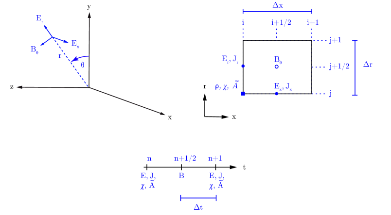
The sequence of operations needed to solve the equations in cylindrical symmetry outlined in the previous section is the same as the one used to solve the model equations in 3D, explained in [13, 14]. The major differences rely in the spatial discretiziation of the physical quantities on the grid in cylindrical geometry and the correspondent solvers. Although the fields are defined on a 2D grid, the particles positions and momenta are defined in the 3D space. The coordinate axes used in the cylindrical geometry of Smilei are defined as in Fig. 1. The electromagnetic fields are defined in the cell borders and interior according to a Yee-like cell for the Finite Difference Time Domain solver for Maxwell’s equations [22]. The spatial centering of the electromagnetic fields follows [21], shown in Fig. 1 with the centering of the envelope quantities (envelope and susceptibility). The envelope quantities are centered in time like the electric field in the Yee scheme (see Fig. 1). Using centered finite differences to discretize the derivatives in the envelope equation 2, the cylindrical solver is obtained:
| (5) |
where
| (6) |
The integration timestep, longitudinal and radial mesh cell size are denoted with , and respectively. The subscripts containing and denote the longitudinal and radial indices on the grid and the subscripts containing the time indices, as in Fig. 1. The susceptibility is projected from the particles on the grid similarly to the current and charge density [13, 14].
The cylindrical components of the gradient of the ponderomotive potential , i.e. and ( in cylindrical symmetry) are computed through centered finite differences, to be used in the equations of motions of the particles. To move the particles in the 3D space, the 3D cartesian components of the force acting on the particle are computed, then the modified Boris pusher described in [13, 14] is used to solve the particles equations of motion in terms of the 3D cartesian components of positions and momenta. The final form of the equations of motion read, for electrons:
| (7) | |||
The 3D cartesian modified Boris pusher described in [13, 14] is used to solve Eqs. 7, to avoid the decrease in accuracy observed in the cylindrical version of the Boris pusher [23]. Maxwell’s equations (Eq. 3) are solved following the FDTD method [22], i.e. discretizing the space and time derivatives with centered finite differences, with a staggering in time. The susceptibility is projected as described in [13, 14], but on the cylindrical grid (see Fig. 1). Given the locality of the envelope solver of Eq. 5, the same parallelization strategies used for a standard Yee scheme can be used to exchange the envelope quantities between the sub-domains. For the simulation of external injection of relativistic particle bunches (see section 3 of [14]), the electromagnetic field initialization procedure described in [24, 14] can be easily implemented in cylindrical symmetry, as described in [25].
4 Benchmarks
In this section we report three benchmark cases to test the envelope model in cylindrical symmetry.
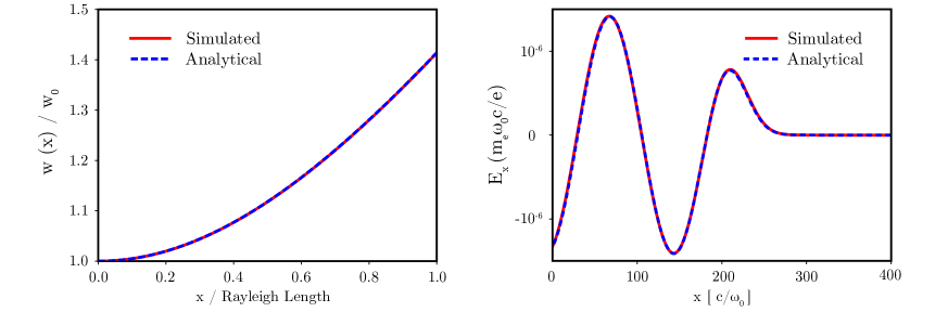
In the left panel of Fig. 2, the simulated evolution of the waist size of a Gaussian laser pulse of initial waist is reported. The laser pulse temporal profile has a FWHM duration in intensity. The longitudinal and radial resolutions are , and the integration timestep is equal to . The evolution of follows the analytical Rayleigh’s law , where is the propagation distance.
The simulation of the excitation of an electron plasma wave in the 1D linear regime is reported as second benchmark. The laser pulse has an initial peak amplitude , initial waist and initial FWHM duration in field . The plasma has a uniform initial density . The longitudinal and radial resolutions are , and the integration timestep is equal to . The plasma is sampled with 6 particles per cell. The computed longitudinal electric field in the wake of a laser pulse compared with its analytical value (Eq. 38a of [26]) after a propagation distance in the right panel of Fig. 2. A very good agreement with the analytical 1D theory can be inferred.
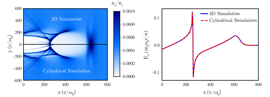
Finally, the preliminary results of a more complex benchmark are reported. The benchmark consists in a nonlinear laser wakefield excitation, with the self-injection and acceleration of an electron beam. The results of a 3D envelope simulation are compared with those of the cylindrical envelope implementation. The laser and simulation parameters of the 3D simulation are those of the “simulation 4” from [14], reported here for the reader’s convenience. A Gaussian laser pulse with waist m, and FWHM duration in intensity fs (total energy 15 J) is focused at the start of a plasma with plateau density cm-3. Since the physical setup is cylindrically symmetric, we expect very similar results with a cylindrical implementation of the envelope model. The plasma is sampled with 8 and 6 particles per cell in the 3D and in the cylindrical simulation respectively. In both simulations, the longitudinal mesh cell size and integration timestep are and . The transverse mesh cell size in the 3D simulation and cylindrical simulation are and respectively. An uncompensated binomial filter (7 passes) [5, 27] has been applied to the envelope simulation to reduce the effects of the numerical Cherenkov radiation [28]. Figure 3 compares the simulated electron density and the longitudinal electric field on axis after 7.6 mm of propagation. The main features of wake excitation and the injection are well modeled by the cylindrical simulation, with a very good agreement in the longitudinal electric field even after a distance of the order of millimiters. In Table 1, the injected electron beam parameters obtained with the two simulations at 7.6 mm (see Table 3 of [14] and relative discussion) are reported. A very good agreement is found in the injected beam charge and energy. The beam energy spread is times larger in the cylindrical simulation. This could be caused by the numerical noise on axis, typical of cylindrical PIC simulations, due to high charge macroparticles crossing the propagation axis [29] or to the boundary conditions on the axis. We note a significantly higher emittance in the cylindrical simulation too, probably caused by the same effects. Further studies are necessary to find other possible causes, for example a higher growth rate of numerical Cherenkov radiation [28] with a cylindrical FDTD solver.
Normally most of the LWFA set ups have a near-cylindrical symmetry, i.e. only 2 azimuthal modes are necessary to simulate them [21], where the laser is modeled through the azimuthal mode 1. In this particular set up the high frequency oscillations of the laser can be neglected and an envelope model can be used. In this case, the azimuthal mode 1 is not necessary and only the mode 0 (representing the perfect cylindrical symmetry) can be used to perform preliminary scans or data analysis. Thus, a cylindrical envelope model can be of great benefit for the quick study of LWFA, as demonstrated in [29, 30]. In our particular benchmark the cylindrical simulation needed a total of cpu-hours (distributed on 320 cpus), while the 3D envelope simulation needed a total amount of resources 1200 times greater (both referred to 7.6 mm of propagation). In our case, since the integration timestep, the mesh resolution, the longitudinal and transverse physical dimension of the simulation domain are the same (half transverse domain in the case of the cylindrical simulation), with the hypothesis that the cost scales linearly with the number of particles, the general speedup can be estimated as
| (8) |
In our case the longitudinal and transverse number of cells of the moving window occupied by the plasma particles is the same, i.e. and respectively. The number of particles per cell in the two simulations are and . With the given values, we indeed obtain an estimated speed-up of using Eq. 8.
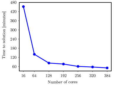
Figure 4 reports the time needed by the benchmark simulation (7.6 mm of propagation) varying the number of processors. With 12 standard compute nodes, the time needed is a few minutes per mm of propagation in the plasma.
| Simulation | [GeV] | [pC] | [%] | [mm-mrad] | |
| 3D | 1.13 | 24 | 2.0 | 0.4 | |
| cylindrical | 1.10 | 27 | 3.2 | 3.5 |
5 Conclusions
We have described the implementation in cylindrical symmetry in the PIC code Smilei of the envelope model presented in [13]. Its speed allows parametric scans and quick analysis of LWFA experimental set ups where the high frequency oscillations of the laser can be neglected and only their averaged (ponderomotive) effects need to be considered. Preliminary results of comparisons with 3D envelope simulations show an acceptable agreement in the injected electron beam charge and energy, with a total amount of resources smaller by three orders of magnitude.
Acknowledgements
F. Massimo was supported by P2IO LabEx (ANR-10-LABX-0038) in the framework “Investissements d’Avenir” (ANR-11-IDEX-0003-01) managed by the Agence Nationale de la Recherche (ANR, France). This work was granted access to the HPC resources of TGCC under the allocation 2018-A0050510062 made by GENCI. The authors are grateful to the TGCC engineers for their support. The authors thank the engineers of the LLR HPC clusters for resources and help. The authors are grateful to the ALaDyn and Smilei development teams for the help and discussions during the development of the envelope model, in particular D. Terzani, A. Marocchino, S. Sinigardi, M. Grech, M. Lobet and F. Pérez, and to Gilles Maynard for fruitful discussions.
References
- [1] T. Tajima and J. M. Dawson. Laser electron accelerator. Phys. Rev. Lett., 43:267–270, Jul 1979.
- [2] V. Malka, S. Fritzler, E. Lefebvre, M.-M. Aleonard, F. Burgy, J.-P. Chambaret, J.-F. Chemin, K. Krushelnick, G. Malka, S. P. D. Mangles, Z. Najmudin, M. Pittman, J.-P. Rousseau, J.-N. Scheurer, B. Walton, and A. E. Dangor. Electron acceleration by a wake field forced by an intense ultrashort laser pulse. Science, 298(5598):1596–1600, 2002.
- [3] E. Esarey, C. B. Schroeder, and W. P. Leemans. Physics of laser-driven plasma-based electron accelerators. Rev. Mod. Phys., 81:1229–1285, Aug 2009.
- [4] V. Malka. Laser plasma accelerators. Physics of Plasmas, 19(5):055501, 2012.
- [5] C. K. Birdsall and A. B. Langdon. Plasma Physics via Computer Simulation. Taylor and Francis Group, 2004.
- [6] X. Davoine, E. Lefebvre, J. Faure, C. Rechatin, A. Lifschitz, and V. Malka. Simulation of quasimonoenergetic electron beams produced by colliding pulse wakefield acceleration. Physics of Plasmas, 15(11):113102, 2008.
- [7] Patrick Mora and Jr. Thomas M. Antonsen. Kinetic modeling of intense, short laser pulses propagating in tenuous plasmas. Physics of Plasmas, 4(1):217–229, 1997.
- [8] D. F. Gordon, W. B. Mori, and T. M. Antonsen. A ponderomotive guiding center particle-in-cell code for efficient modeling of laser-plasma interactions. IEEE Transactions on Plasma Science, 28(4):1135–1143, Aug 2000.
- [9] C. Huang, V.K. Decyk, C. Ren, M. Zhou, W. Lu, W.B. Mori, J.H. Cooley, T.M. Antonsen, and T. Katsouleas. Quickpic: A highly efficient particle-in-cell code for modeling wakefield acceleration in plasmas. Journal of Computational Physics, 217(2):658 – 679, 2006.
- [10] Benjamin M. Cowan, David L. Bruhwiler, Estelle Cormier-Michel, Eric Esarey, Cameron G.R. Geddes, Peter Messmer, and Kevin M. Paul. Characteristics of an envelope model for laser–plasma accelerator simulation. Journal of Computational Physics, 230(1):61 – 86, 2011.
- [11] Carlo Benedetti, Eric Esarey, Wim P. Leemans, and Carl B. Schroeder. Efficient Modeling of Laser-plasma Accelerators Using the Ponderomotive-based Code INF&RNO. In Proceedings, 11th International Computational Accelerator Physics Conference (ICAP 2012): Rostock-Warnemünde, Germany, August 19-24, 2012, page THAAI2, 2012.
- [12] A. Helm, J. Vieira, L. Silva, and R. Fonseca. Implementation of a 3D version of ponderomotive guiding center solver in particle-in-cell code OSIRIS. In APS Meeting Abstracts, page GP10.011, October 2016.
- [13] Davide Terzani and Pasquale Londrillo. A fast and accurate numerical implementation of the envelope model for laser-plasma dynamics. Computer Physics Communications, 242:49 – 59, 2019.
- [14] Francesco Massimo, Arnaud Beck, Julien Derouillat, Mickael Grech, Mathieu Lobet, Frederic Perez, Imen Zemzemi, and Arnd Specka. Efficient start-to-end 3d envelope modeling for two-stage laser wakefield acceleration experiments. Plasma Physics and Controlled Fusion, 2019.
- [15] B. Cros, B.S. Paradkar, X. Davoine, A. Chancé, F.G. Desforges, S. Dobosz-Dufrénoy, N. Delerue, J. Ju, T.L. Audet, G. Maynard, M. Lobet, L. Gremillet, P. Mora, J. Schwindling, O. DelferriÚre, C. Bruni, C. Rimbault, T. Vinatier, A. Di Piazza, M. Grech, C. Riconda, J.R. MarquÚs, A. Beck, A. Specka, Ph. Martin, P. Monot, D. Normand, F. Mathieu, P. Audebert, and F. Amiranoff. Laser plasma acceleration of electrons with multi-pw laser beams in the frame of cilex. Nuclear Instruments and Methods in Physics Research Section A: Accelerators, Spectrometers, Detectors and Associated Equipment, 740:27 – 33, 2014. Proceedings of the first European Advanced Accelerator Concepts Workshop 2013.
- [16] A. J. Gonsalves, K. Nakamura, J. Daniels, C. Benedetti, C. Pieronek, T. C. H. de Raadt, S. Steinke, J. H. Bin, S. S. Bulanov, J. van Tilborg, C. G. R. Geddes, C. B. Schroeder, Cs. Tóth, E. Esarey, K. Swanson, L. Fan-Chiang, G. Bagdasarov, N. Bobrova, V. Gasilov, G. Korn, P. Sasorov, and W. P. Leemans. Petawatt laser guiding and electron beam acceleration to 8 gev in a laser-heated capillary discharge waveguide. Phys. Rev. Lett., 122:084801, Feb 2019.
- [17] E. Adli, A. Ahuja, O. Apsimon, R. Apsimon, A. M. Bachmann, D. Barrientos, F. Batsch, J. Bauche, V. K. Berglyd Olsen, M. Bernardini, T. Bohl, C. Bracco, F. Braunmüller, G. Burt, B. Buttenschön, A. Caldwell, M. Cascella, J. Chappell, E. Chevallay, M. Chung, D. Cooke, H. Damerau, L. Deacon, L. H. Deubner, A. Dexter, S. Doebert, J. Farmer, V. N. Fedosseev, R. Fiorito, R. A. Fonseca, F. Friebel, L. Garolfi, S. Gessner, I. Gorgisyan, A. A. Gorn, E. Granados, O. Grulke, E. Gschwendtner, J. Hansen, A. Helm, J. R. Henderson, M. Hüther, M. Ibison, L. Jensen, S. Jolly, F. Keeble, S. Y. Kim, F. Kraus, Y. Li, S. Liu, N. Lopes, K. V. Lotov, L. Maricalva Brun, M. Martyanov, S. Mazzoni, D. Medina Godoy, V. A. Minakov, J. Mitchell, J. C. Molendijk, J. T. Moody, M. Moreira, P. Muggli, E. Öz, C. Pasquino, A. Pardons, F. Peña Asmus, K. Pepitone, A. Perera, A. Petrenko, S. Pitman, A. Pukhov, S. Rey, K. Rieger, H. Ruhl, J. S. Schmidt, I. A. Shalimova, P. Sherwood, L. O. Silva, L. Soby, A. P. Sosedkin, R. Speroni, R. I. Spitsyn, P. V. Tuev, M. Turner, F. Velotti, L. Verra, V. A. Verzilov, J. Vieira, C. P. Welsch, B. Williamson, M. Wing, B. Woolley, and G. Xia. Acceleration of electrons in the plasma wakefield of a proton bunch. Nature, 561(7723):363–367, 2018.
- [18] J. Derouillat, A. Beck, F. Pérez, T. Vinci, M. Chiaramello, A. Grassi, M. Flé, G. Bouchard, I. Plotnikov, N. Aunai, J. Dargent, C. Riconda, and M. Grech. Smilei : A collaborative, open-source, multi-purpose particle-in-cell code for plasma simulation. Computer Physics Communications, 222:351 – 373, 2018.
- [19] A. Beck, J. Derouillat, M. Lobet, A. Farjallah, F. Massimo, I. Zemzemi, F. Perez, T. Vinci, and M. Grech. Adaptive simd optimizations in particle-in-cell codes with fine-grain particle sorting. Computer Physics Communications, 244:246 – 263, 2019.
- [20] F. Massimo, S. Atzeni, and A. Marocchino. Comparisons of time explicit hybrid kinetic-fluid code architect for plasma wakefield acceleration with a full pic code. Journal of Computational Physics, 327(Supplement C):841 – 850, 2016.
- [21] A. Lifschitz, X. Davoine, E. Lefebvre, J. Faure, C. Rechatin, and V. Malka. Particle-in-Cell modelling of laser–plasma interaction using Fourier decomposition. Journal of Computational Physics, 228(5):1803–1814, November 2008.
- [22] K. Yee. Numerical solution of inital boundary value problems involving maxwell’s equations in isotropic media. IEEE Transactions on Antennas and Propagation, 14:302–307, May 1966.
- [23] G.L. Delzanno and E. Camporeale. On particle movers in cylindrical geometry for particle-in-cell simulations. Journal of Computational Physics, 253:259 – 277, 2013.
- [24] J.-L. Vay. Simulation of beams or plasmas crossing at relativistic velocity. Physics of Plasmas, 15(5):056701, 2008.
- [25] F. Massimo, A. Marocchino, and A.R. Rossi. Electromagnetic self-consistent field initialization and fluid advance techniques for hybrid-kinetic pwfa code architect. Nuclear Instruments and Methods in Physics Research Section A: Accelerators, Spectrometers, Detectors and Associated Equipment, 829(Supplement C):378 – 382, 2016. 2nd European Advanced Accelerator Concepts Workshop - EAAC 2015.
- [26] Rémi Lehe, Manuel Kirchen, Igor A. Andriyash, Brendan B. Godfrey, and Jean-Luc Vay. A spectral, quasi-cylindrical and dispersion-free particle-in-cell algorithm. Computer Physics Communications, 203:66 – 82, 2016.
- [27] J.-L. Vay, C.G.R. Geddes, E. Cormier-Michel, and D.P. Grote. Numerical methods for instability mitigation in the modeling of laser wakefield accelerators in a lorentz-boosted frame. Journal of Computational Physics, 230(15):5908 – 5929, 2011.
- [28] R. Lehe, A. Lifschitz, C. Thaury, V. Malka, and X. Davoine. Numerical growth of emittance in simulations of laser-wakefield acceleration. Phys. Rev. ST Accel. Beams, 16(2):021301, 2013.
- [29] C. Benedetti, C. B. Schroeder, E. Esarey, C. G. R. Geddes, and W. P. Leemans. Efficient modeling of laser-plasma accelerators with inf&rno. AIP Conference Proceedings, 1299(1):250–255, 2010.
- [30] C Benedetti, C B Schroeder, C G R Geddes, E Esarey, and W P Leemans. An accurate and efficient laser-envelope solver for the modeling of laser-plasma accelerators. Plasma Physics and Controlled Fusion, 60(1):014002, 2018.