SMAUG: End-to-End Full-Stack Simulation Infrastructure for Deep Learning Workloads
Abstract
In recent years, there has been tremendous advances in hardware acceleration of deep neural networks. However, most of the research has focused on optimizing accelerator microarchitecture for higher performance and energy efficiency on a per-layer basis. We find that for overall single-batch inference latency, the accelerator may only make up 25-40%, with the rest spent on data movement and in the deep learning software framework. Thus far, it has been very difficult to study end-to-end DNN performance during early stage design (before RTL is available) because there are no existing DNN frameworks that support end-to-end simulation with easy custom hardware accelerator integration. To address this gap in research infrastructure, we present SMAUG, the first DNN framework that is purpose-built for simulation of end-to-end deep learning applications. SMAUG offers researchers a wide range of capabilities for evaluating DNN workloads, from diverse network topologies to easy accelerator modeling and SoC integration. To demonstrate the power and value of SMAUG, we present case studies that show how we can optimize overall performance and energy efficiency for up to 1.8-5 speedup over a baseline system, without changing any part of the accelerator microarchitecture, as well as show how SMAUG can tune an SoC for a camera-powered deep learning pipeline.
I Introduction
The tremendous popularity of deep learning (DL) in recent years has been fueled by the increased capability of DL hardware and software systems. In particular, for both performance and energy efficiency, dedicated hardware accelerators for deep neural networks (DNNs) have received a phenomenal amount of interest [1, 2, 3, 4, 5, 6, 7]. Much of the focus on DNN accelerator design has been on optimizing core datapaths and dataflows to improve local reuse of data and reduce expensive data movement between the processing elements, local storage, and DRAM, on a per-layer basis. However, at the end of the day, end-to-end performance is what truly matters, and additional overheads must be considered, such as data layout transformations that shuffle and reshape the data, the choice of accelerator interfacing with the SoC which affects data movement efficiency, management of multiple independently programmed accelerators, and contention for shared system resources like memory bandwidth between different agents on the SoC.
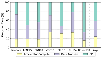
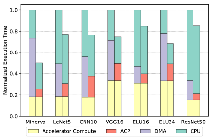
As a motivating example of why overall performance is important, we profile end-to-end single-batch inference latency on a range of image classification DNNs and break down the overall time spent on accelerator compute, data transfer to/from scratchpads, and CPU time spent in the software stack, on a system with one DNN accelerator connected over DMA. In this paper, we define the term “accelerator” to refer to any independently programmable hardware block specialized for a few particular operations. Figure 1 shows that out of the entire execution time, only 25% on average is spent waiting on accelerator compute, with the rest of the time taken up by data transfer (34%) and CPU processing (42%), performing tasks like data layout transformations, tiling, and more. This is particularly the case on a network like ResNet50 because of the many expensive tiling operations between each of the 50 layers. In some respects, this breakdown is not surprising because the performance speedups offered by DNN accelerators can easily make software the primary bottleneck of overall latency. Nonetheless, this analysis shows several opportunities for optimization that would not have been revealed by a layer-by-layer analysis, which this paper will explore in more depth. The impact of software stack time on overall performance has also been observed on industry-grade deep learning models written in TensorFlow [8] and Caffe2 [9].
| End-to-End Evaluation | Simulation Support | Easy Custom Backend Integration | Simulation Speed | |
|---|---|---|---|---|
| TensorFlow [10], PyTorch [11], Caffe/Caffe2 [12], MXNet [13] |
✔ |
✗ |
✗ |
N/A |
| DNNWeaver [14], DNNBuilder [15], MAGNet [16] |
✗ |
✔ (accelerator TLM/RTL simulation only) | ✗ (requires RTL/HLS or detailed timing models) | Varies |
| TVM/VTA [17] |
✔ |
✔ (behavioral simulation for template accelerator) | ✗ (requires RTL/HLS) | Fast |
| SCALE-Sim [18], HSIM-DNN [19] |
✗ |
✔ (accelerator analytical model) | ✗ (backend specific) | Fast |
| SMAUG |
✔ |
✔ ✔ (flexible accelerator and SoC modeling) | ✔ (no RTL required) | Fast |
Consequently, in order to holistically design DNN-centric SoCs, we must be able to study end-to-end behavior in simulation, as simulation is the usual methodology to evaluate early-stage/pre-RTL hardware designs. However, as shown in Table I, there is no DNN framework available that supports fast, early-stage design exploration in simulation. Productivity-oriented frameworks like TensorFlow or PyTorch don’t support simulation at all, and the ones that do support end-to-end simulation all require RTL/HLS for custom hardware accelerator integration, which is slow to write/generate and slow to simulate as well.
To address this gap in research infrastructure, we describe SMAUG: Simulating Machine Learning Applications Using gem5-Aladdin. gem5-Aladdin is an SoC simulator that supports modeling of complex heterogeneous SoCs [20], and SMAUG is the first architecture-simulation friendly deep learning framework. We wrote SMAUG to be compatible with gem5-Aladdin because it is built on the familiar gem5 simulator, supports flexible SoC, accelerator, and memory topologies, and also does not require RTL for design space exploration of accelerators, all of which greatly simplify the research and development process. SMAUG is designed to enable DNN researchers to rapidly evaluate different accelerator and SoC designs and perform hardware-software co-design, not to replace existing frameworks. SMAUG currently is targeted at DNN inference, but we plan to incorporate support for training as well.
SMAUG’s headline features include a Python API for easy network configuration, support for a wide range of commonly used operators and network topologies, various hardware accelerator implementations of core kernels with easy plug-and-play of new custom operators, and a complete software stack that manages operator tiling, multi-accelerator and multi-thread scheduling, synchronization, and more. In addition, SMAUG solves several key problems of building architecture-simulation friendly deep learning frameworks:
-
1.
New accelerators are easy to implement in SMAUG’s modular architecture. They can be implemented in just a few lines of code with Aladdin, or as a native gem5 object for more control over cycle-level timing.
-
2.
Running a complete forward pass through a DNN may require billions of operations, but for many core kernels, most of that work looks the same. SMAUG supports sampling of accelerator simulation through new easy-to-use Aladdin APIs, with error as low as 1% for even the most aggressive sampling factors.
-
3.
Workarounds are provided for various simulator limitations to make up for the lack of complete OS feature support, such as a thread scheduler.
To illustrate the capabilities of SMAUG and the kinds of insights that only end-to-end DNN studies can provide, we present several case studies demonstrating how to improve overall performance of various DNNs by 45-79% (1.8- speedup) over a baseline system without any changes to the accelerator microarchitecture itself:
-
1.
Using different SoC-accelerator interfaces to achieve tighter coupling between the CPU and accelerators for 17-55% overall speedup and up to 56% energy wins.
-
2.
Using multiple independent accelerators to exploit tile-level parallelism in DNNs for 24-62% overall speedup with eight accelerators over a single accelerator system.
-
3.
Using multithreading in the software stack to optimize data preparation time for up to 37% overall speedup.
Finally, we demonstrate how SMAUG can be integrated with a state-of-the-art camera pipeline, implemented in Halide, to model even more complex applications and identify opportunities for more efficient system design.
II SMAUG Framework
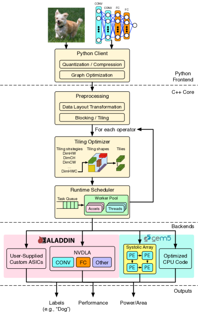
Figure 3 illustrates the overall architecture and execution flow of SMAUG. It is divided into three major components: a Python frontend for network configuration, a C++ runtime to manage the execution flow, and a backend consisting of a set of hardware-accelerated kernels. The accelerated kernels can be modeled either using Aladdin or as a native gem5 simulation object, depending on the user’s desired level of flexibility and control.
Users begin by building a network using a declarative Python API, complete with all input and weights data (which can optionally be taken from an existing trained model). They also specify in the configuration which set of accelerated kernels they want to use, the level of data quantization, and other metadata. The complete network specification is then converted into a dataflow graph and serialized (along with network parameters). This is a one-time operation for each network, so it is done as a separate step. The serialized model is loaded into the C++ runtime, and SMAUG begins a set of offline preprocessing steps. For example, certain read-only tensors (weights data) are pre-tiled (split into smaller contiguous tensors) during this preprocessing step to reduce time on the critical path. This preprocessing can also be fast forwarded in simulation to save time. Next, SMAUG invokes a tiling optimizer to compute the best available tiling shapes for each operation, so that the tiles utilize as much of the accelerator compute and memory resources as possible. Finally, SMAUG dispatches each tile of work to the appropriate processing elements, waits for them to finish, gathers all the results, and prepares for the next operation. If multiple independent PEs are available, SMAUG can schedule all of them at once. Since the internal representation of the network is a graph, arbitrarily complex networks can be defined and scheduled; the architecture is not limited to linearly-stacked layers. Multithreading support is available to parallelize CPU operations when possible and better utilize available shared resources like memory bandwidth.
As its name implies, SMAUG is compatible with the LLVM-based toolchains required by the Aladdin accelerator simulator and the gem5 APIs it exposes [20]. We have made extensive improvements to these toolchains to support compiling C++ binaries, tracing multi-threaded workloads, supporting sampling, and more. In the following sections, we will describe the frontend Python API, core runtime, hardware backend modeling and simulation workarounds in more detail.
II-A Python API
Many deep learning frameworks use Python APIs to build models, and we wanted to follow in this same tradition to lessen the learning curve, rather than forcing users to manually write configuration files or learn a new DSL. Figure 2 shows how a residual unit might be built:
def create_residual_unit(): with Graph(name="residual", backend="MyBackend") as g: # Tensor initialization. inputs = Tensor(np.random.rand(1, 8, 32, 32))) filter0 = Tensor(np.random.rand(64, 3, 3, 3))) filter1 = Tensor(np.random.rand(8, 64, 3, 3))) # If quantitization is desired: # filter0 = filter0.astype(np.float16) # Network topology: act = input_data("input", input_tensor) x = convolution("conv0", act, filter0, stride=[1, 1], padding="same", activation="relu") x = convolution("conv1", x, filter1, stride=[1, 1], padding="same") out = add("add", x, act, activation="relu") # residual return ggraph = create_residual_unit()graph.write_graph() # Graph serialization.
This small example demonstrates the simplicity and familiarity of building networks in SMAUG. They are specified in a deferred execution style, and by using with-statement context managers, we can greatly reduce boilerplate without adding global state. All input tensors must be constructed inside the context before being used in an operator. Finally, the user can either supply random data or existing trained parameters as well as the data type (e.g. float16 or float32). Certain optimizations like operator fusion (e.g. convolution + element-wise operators) are applied automatically by the framework. Finally, the user serializes the model specification and parameters; parameters are stored separately so that they can be easily swapped.
II-B Tiling Optimizer
Due to the limited amount of local storage on an accelerator, individual layers of DNNs often have too many weights and/or inputs to run at once, thus requiring the operation to be tiled. Whenever tiling is required, redundant data movement is likely necessary, so identifying efficient tiling schedules (also called “loop nests”) that maximize data reuse and minimize data movement between levels of the memory hierarchy is critical to achieving high performance. This has been studied extensively in the field; however, the general problem of finding the optimal solution is combinatorial in dimensionality and tiling factors, and beyond the scope of this work.
In SMAUG, we circumvent a general solution by implementing a specialized tiling optimizer for each dataflow implemented by an accelerator, because any particular instantiation of an accelerator implements at most a few dataflows which exploit particular parallelism patterns. As an example, consider the dataflow of the Nvidia Deep Learning Accelerator (NVDLA), which we use in our experiments (see Section III for details). This dataflow, described in Figure 4, reduces partial products in the channel dimension, so it benefits from a tiling schedule that maximizes the channel dimension of the input and weight tiles. But such a schedule is not suitable for an accelerator that computes 1D or 2D convolutions, like the row-stationary dataflow [2]. By specializing the optimizer for a specific dataflow, we restrict the search space to a narrower set of possibilities that can be exhaustively explored. The final schedule is one that maximizes both the utilization of the local scratchpads and the functional units.
BUFFER IN[IN_R][IN_C][IN_H];BUFFER WGT[NUM_PES][WGT_R][WGT_C][IN_H];BUFFER OUT[NUM_PES][OUT_R][OUT_C];parallel for (pe = 0 to NUM_PES) for (kr = 0 to WGT_R - 1) for (kc = 0 to WGT_C - 1) for (cb = 0 to IN_H/32 - 1) { // cb = channel block // Each PE has its own weight reg. BUFFER wgt_reg[0:31] = WGTS[pe][kr][kc][cb:cb+31]; // Now iterate over the input rows and cols. for (r = 0 to OUT_R - 1) for (c = 0 to OUT_C - 1) parallel for (h = 0 to 31) { // 32-way spatial reduction in channel // dimension. OUT[r][c][pe] += IN[r+kr][c+kc][cb*32+h] * wgt_reg[h]; } }
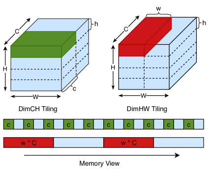
The first major step of the tiling optimizer is to identify a tiling strategy, i.e. the best dimensions along which to tile the input and output tensors. If an input tensor is of shape , there are four possible dimensions to tile the tensor, and the best choice depends on two factors. The first is the accelerator: the dataflow it implements and the minimum number of elements along the dimensions that maximize usage of the functional units. For example, if the accelerator reduces partial products along the channel dimension, and it implements a 32-way reduction unit, each tile should have a multiple of 32 channels while also fitting inside the accelerator’s scratchpads. The second factor is data layout of the tensor, which determines the amount of work required to shuffle and reshape the original input tensor into these tiles. This is a consideration that only arises when evaluating end-to-end performance.
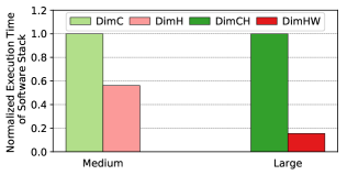
As an example, Figure 5 shows how one NHWC tensor, when tiled in two different ways, produces two very different memcpy patterns. We describe a tiling strategy with the notation DimXYZ, where X, Y, and Z are the tiled dimensions. For this tensor, channels are the innermost dimension, so it is the most expensive to tile. To quantify this difference, we show in Figure 6 how long it takes to tile two different tensors two different ways for a max tile size of 16,384 elements. The medium-sized tensor (1x16x16x128) can be tiled channel-wise (1x16x16x64) or row-wise (1x8x16x128), but row-wise is faster in software because it only requires two large memcpys of 8x16x128 = 16K contiguous elements, whereas for channel-wise tiling requires 512 memcpys of 64 elements. This effect is even more pronounced on the larger layer, where we can use either DimCH (1x32x64x8) or DimHW (1x1x32x512). DimHW tiling is faster to complete because it only requires 128 memcpys of 16K elements to completely tile the input, compared to 262K memcpys of 8 elements. The effect of a different tiling strategy on the overall operation is harder to predict. For element-wise operations, tiling strategy has next to no effect; for operations whose performance depends on exploiting data reuse, changing tiling shape may impact overall runtime. This is one of the new tradeoffs SMAUG enables researchers to explore.
The second major step of the tiling optimizer is to compute the best tile shapes given the tiling strategy and max tile size. Depending on the chosen strategy and operator parameters, this process is surprisingly complex and can encounter an incredible number of edge cases, all of which must be handled for correctness and efficiency. Considerations include halo regions around the entire tensor due to zero-padding, overlapping regions around each tile, interactions with ¿ 1 stride sizes, and more. In most cases, input tile shapes are not uniform and thus produce differently sized output tiles.
II-C Runtime Scheduler
Once the tiling shapes have been generated for each operator’s tensors, the scheduler prepares the tensor for computation by splitting it into the specified tile shapes. This has to wait until runtime, when the actual input data from the previous operator is ready. Then, the scheduler dispatches each tile to the appropriate compute element. If there are multiple compute elements and tile-level parallelism exists, SMAUG can dispatch independent work to multiple compute elements at once. To help distribute work across multiple accelerators, SMAUG implements an accelerator worker pool and a command queue per accelerator. Tasks are pushed onto the command queue for the next available accelerator in the pool. Any operators that are not supported in the backend hardware accelerators are executed on the CPU instead. As the work completes, the scheduler gathers the tiled output data back into one contiguous tensor. Since the gem5-Aladdin API exposes an accelerator like a thread, managing multiple accelerators concurrently running is as straightforward as starting and joining on threads. SMAUG also supports dividing CPU work across multiple threads, but since gem5’s syscall-emulation mode does not have a thread scheduler, SMAUG implements a thread pool with round-robin scheduling of tasks from a work queue.
II-D Backends
The backends run the convolutions/inner products/etc. required by the model. In SMAUG, we provide a complete set of hardware accelerated kernels for all the included operators. These models can be written using Aladdin or as a native gem5 object, depending on the user’s desired level of flexibility and control. We provide examples of both, most notably a convolution engine inspired by NVDLA, written with Aladdin, and a configurable systolic array, written as a native cycle-level gem5 object.
The NVDLA-inspired convolution engine consists of eight PEs, each with a 32-way multiply-accumulate (MACC) array that operates on a different output feature map. The dataflow is described in Figure 4. Inputs and weights are 16-bit fixed point, while outputs are accumulated in 32-bit fixed point and reduced to 16-bit before being written to the scratchpad. In the emerging vernacular used to describe DNN dataflows, this dataflow is L0 weight-stationary (weights are reused every cycle at the register level within a MACC array), and L1 input/output stationary (for every weight, inputs are re-read and outputs are accumulated in-place in the SRAMs). It is backed by three SRAMs, one each for inputs, weights, and outputs. We only model the core datapath and dataflow of NVDLA, not other features like its convolution buffer.
The systolic array’s dataflow is output stationary: inputs stream through from the left, while weights stream from the top. There are three scratchpads, accessed from fetch and commit units, to supply the PEs with data. The dataflow was inspired by SCALE-Sim [18], but SCALE-Sim is primarily an analytical model that can generate SRAM and memory traces to feed to other tools like DRAMSim, whereas our model is entirely execution-driven and produces live memory traffic that affects (and is affected by) the rest of the system.
One of the key design features of SMAUG is how easy it is to implement a new HW accelerator model and integrate into the framework, particularly if the user chooses to use Aladdin for modeling. For example, apart from syntax and variable declarations, Figure 4 is very similar to the code that models the convolution engine. In fact, merely 5% of the code is used to model all the hardware blocks with Aladdin. If users do choose to write cycle-level timing models using native gem5 APIs, then more code is needed (the systolic array model accounts for 10% of the SMAUG codebase). The remaining 85% is devoted to computing tiling schedules, memory management, data movement, cache coherency, and task scheduling. Therefore, SMAUG eases the development of not only new hardware models, but also studies of end-to-end system interactions, enabling researchers to spend their time on the topics that interest them the most.
II-E Working with Simulator Limitations
In order to simulate end-to-end networks in user-level simulators (like gem5 syscall-emulation mode), there are three constraints that must be addressed: reducing simulation time with sampling, handling incomplete system call emulation, and supporting multi-threading without a thread scheduler (typically implemented in the kernel).
II-E1 Sampling Support
Modern DNNs are very deep and compute intensive, often requiring billions of operations, and because Aladdin is a trace based simulator, it may be infeasible to store and simulate a complete forward pass. However, since DNN computation is so regular, a sampling approach works well.
int reduction(int* a, int size, int sample) { // Generally avoid sampling loops containing data // transfer operations to avoid changing the memory // footprint of the application. dmaLoad(a, size * sizeof(int)); int result = 0; setSamplingFactor("loop", (float)size / sample); loop: // Run only ‘sample‘ iterations of this loop; the result // might be wrong, but that’s expected for sampling. for (int i = 0; i < sample; i++) result += a[i]; return result;}
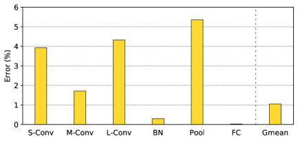
We extended Aladdin to support sampling at the per-loop level with a new API called setSamplingFactor, in which the user specifies how many iterations of the loop to trace and simulate. Figure 7 demonstrates the API at work. During Aladdin’s graph optimization process, we build a loop tree that captures the hierarchy of loop iterations. When the simulation is over, Aladdin examines each node in the loop tree, unsamples the latency of simulated iterations, and propagates the sampled execution time up the tree. After every loop is unsampled, Aladdin produces a final overall cycles estimate. This API supports pipelined loops as well, although at least two loop iterations are required to determine the pipeline latency. As a result, we can simulate a forward pass of ResNet50 in just 5 hours. In our experiments, we only sample loops containing only computation, not loops containing large data transfers, so that the memory footprint of the sampled network is unchanged. We validated our sampling technique for a range of operators and input shapes, all at the highest sampling factors (so that the sampled loops only run one or two iterations). Figure 8 shows that sampled execution has less than 6% error across different kernel types, with an average of just 1%. Finally, note that sampled simulation will obviously produce incorrect functional results, since not all the code is being executed, so this is only suitable for loops whose control flow is not data dependent.
II-E2 System call emulation
User-space simulators often do not implement the full range of OS features that we come to take for granted. For example, the mmap syscall can map the contents of a file into memory (among other use cases), so it can be manipulated directly via loads and stores rather than through the IO subsystem, but in gem5 syscall-emulation mode, stores to mmapped memory are not synchronized to the backing file. SMAUG was written to work within all of these limitations; it compiles into a single C++ binary, never forks other processes, and interacts minimally with the OS, essentially only requiring the ability to access a filesystem, call printf, and start new threads that never exit.
II-E3 Multithreading support
It is common for user-level simulators to not implement pre-emptive thread schedulers, as thread scheduling is a kernel task. gem5 syscall emulation mode has limited support for multi-threading, with limitations on how thread contexts can be reused after a thread exits. To enable multi-threading in SMAUG, we implemented a custom thread pool and expose an API to dispatch work to it. Each task is executed to completion before yielding the CPU. Furthermore, to prevent idle threads from spinning endlessly in simulation and generating useless work that slows down the simulation, we use gem5 hooks to quiesce CPUs while they’re waiting for work and wake them only when we assign them tasks.
III Methodology
Now that we have described SMAUG, we will demonstrate how it can be used to provide insights into accelerated DNN performance that per-layer studies would not be able to show. First, we discuss our evaluation methodology.
III-A Baseline System
| Component | Parameters |
| CPU Core | 8 Out-of-order X86 cores @2.5GHz 8-op issue width, 192-entry ROB |
| L1 Cache | 64KB i-cache & d-cache, 4-way associative, 32B cacheline, LRU, 2-cycle access latency |
| L2 Cache | 2MB, 16-way, LRU, MESI coherence, 20-cycle access latency |
| DRAM | LP-DDR4, @1600MHz, 4GB, 4 channels, 25.6GB/s |
| Accels | NVDLA conv engine and others, systolic array (8x8 PEs), 1GHz All scratchpads are 32KB each |
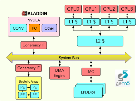
Figure 9 shows the baseline SoC used in this paper, with microarchitectural parameters listed in Table II. In gem5-Aladdin, we use syscall-emulation mode with Ruby to model a MESI coherency protocol. The CPU communicates with the accelerator either via the ioctl system call or via shared memory. The baseline SoC transfers data over DMA and runs a single-threaded software stack. In Section IV (also Figure 1), we run the convolutions and inner products on the NVDLA-inspired accelerator; in Section V, we use the systolic array instead for diversity.
III-B Workloads
| Name | Dataset | Network Topology | Parameters | Accuracy |
| Minerva [21] | MNIST (28x28x1) | 4 FC [784, 256, 256, 10]. | 665KB | 97% |
| LeNet5 [22] | MNIST (28x28x1) | 5 layer CNN (3x3) 2 CONV [32, 32], POOL, FC [128, 10]. | 1.2MB | 98% |
| CNN10 | CIFAR-10 (32x32x3) | 10 layer CNN (3x3) 4 CONV [32, 32, 64, 64], 2 BN, 2 POOL, 2 FC [512, 10]. | 4.2MB | 85% |
| VGG16 [23] | CIFAR-10 (32x32x3) | 16 layer CNN (3x3). 2 CONV [64, 128], POOL, 2 CONV [128, 128], POOL, 3 CONV [256, 256, 256], POOL, 3 CONV [512, 512, 512], POOL, 2 FC: [512, 10]. | 17.4MB | 90% |
| ELU16 [24] | CIFAR-100 (32x32x3) | 16 layer CNN. 1 CONV [192], POOL, 2 CONV [192, 240], POOL, 2 CONV [240, 260], POOL, 2 CONV [260, 280], POOL, 2 CONV [280, 300], POOL, 2 CONV [300, 100]. Mostly 1x1 & 2x2 CONV. | 3.3MB | 71.25% |
| ELU24 [24] | CIFAR-100 (32x32x3) | 24 layer CNN. CONV [384], POOL, 4 CONV [384, 384, 640, 640], POOL, 4 CONV [640, 768, 768, 768], POOL, 3 CONV [768, 896, 896], POOL, 3 CONV [896, 1024, 1024], POOL, 4 CONV [1024, 1152, 1152, 100]. Mostly 1x1 & 2x2 CONV. | 75MB | 77.72% |
| ResNet50 [25] | ImageNet (224x224x3) | 50 layer CNN. 1 CONV [64], 3 stacks of 3 CONV [64, 64, 256], 4 stacks of 3 CONV [128, 128, 512], 6 stacks of 3 CONV [256, 256, 1024], 3 stacks of 3 CONV [512, 512, 2048], 1 FC [1000]. 1x1 & 3x3 CONV. | 237MB | 76.46% |
With the flexible Python client and the complete SW/HW stack in SMAUG, we are able to evaluate a variety of DNN workloads. Here we investigate four image classification tasks: MNIST, CIFAR10, CIFAR100 and ImageNet. For the first three datasets, we select two different networks each. For ImageNet, we use ResNet50 [25] (included in the emerging MLPerf Inference Benchmark [26]). Table III summarizes the networks used. The goal was to cover a diverse set of network topologies that still map well to the accelerator’s dataflow, which is optimized for convolution shapes deep in input/output feature maps.
III-C Simulation Time
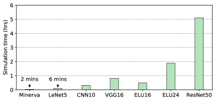
Figure 10 shows the simulation time for running the workloads using the NVDLA backend in SMAUG on an Intel Xeon E5-2697 host (@2.6GHz). For most of the networks, SMAUG simulations finish within 2 hours. The smaller MNIST workloads take less than 10 minutes, and with sampling, even the large ResNet50 network finishes in 5 hours.
III-D Power and Area Modeling
To obtain power and area estimates, we take a multi-pronged approach. We characterize various 16-bit functional units for power and area in a commercial 16nm FinFET process and plug them directly into Aladdin. To model accelerator local scratchpads, we build and characterize a variety of SRAM blocks through a commercial memory compiler in the same technology node. LLC power estimates are obtained from CACTI 7 [27], and DRAM power is modeled by DRAMPower [28], with timing and power parameters taken from a commercial LP-DDR4 product datasheet [29].
IV Optimizing End-to-End Performance of DNN workloads
SMAUG enables a wide range of architecture simulation tasks, from diverse DNN topologies to accelerator implementations, from the SoC integration of accelerators to evaluation of multi-accelerator systems. To illustrate the insights that SMAUG can bring to DL hardware architects, in this section we demonstrate several ways to improve end-to-end DNN performance on an SoC, all without changing the underlying accelerator themselves.
In these case studies, the baseline system uses one NVDLA accelerator with the DMA interface, running on a single-threaded software stack. Figure 1 has shown that not only the accelerator compute, but also data movement and CPU processing spent on “between-the-layer” work are crucial to end-to-end DNN performance. Therefore, in the rest of this section, we present three case studies that attack all these components of performance. First, we optimize data transfers by using a one-way coherent interface between the accelerator and SoC instead of DMA. Second, we explore multi-accelerator systems to exploit tile-level parallelism for greater compute and data-transfer throughput. Third, we optimize tiling transformations in software to reduce CPU processing time. As a whole, these optimizations speed up overall inference latency by 1.8-.
IV-A Improving Data Transfer: Coherent Accelerator-SoC Interfaces
Fixed-function accelerators typically use private scratchpads for local storage and communicate with the memory system of the SoC through a software-managed DMA interface. DMA is the simplest approach to sharing data from a hardware point-of-view, but it requires software to be responsible for explicitly flushing and invalidating cache lines that the accelerator is going to read and/or write, resulting in both costly performance overheads and a challenging programming model where developers must manage complex coherency operations. This has driven researchers to investigate alternative interfaces, such as hardware-managed caches [30, 31, 32, 33, 34]. While cache coherency for programmable accelerators like GPUs have been extensively studied [35, 36, 37, 38, 39, 40], only in recent years have academia and industry started investigating use of caches for fixed-function accelerators and FPGAs. Full cache coherency represents the ideal programming model, but the hardware is more expensive and generally requires the accelerator to maintain a cache, which may not actually suit the accelerated kernel.
In this case study, we explore a recent interface design that occupies a middle ground between SW-managed and fully hardware-managed coherency. Here, the interface provides one-way coherent access from the accelerator to the host memory system. This interface takes the form of a special port, referred to as an accelerator coherency port (ACP), that issues coherent memory requests directly to the CPU’s last level cache (LLC). The LLC handles all coherency traffic on the accelerator’s behalf. This enables the accelerator to access coherent memory without adding more area and complexity. To model such an interface, we augment a standard MESI cache coherence protocol using the Ruby modeling framework with a custom controller. This controller is connected to an accelerator’s memory interface and generates requests to the LLC on behalf of the accelerator. Unlike a standard cache controller, it does not implement a cache and leaves ownership of the relevant cache lines with the LLC rather than the accelerator itself. Using Verilog simulation of an ARM Cortex A53 CPU, we measure ACP hit latency to be 20 cycles, which we set as the LLC latency.
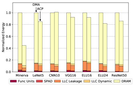
Figure 11 shows the performance and energy of the ACP interface, relative to the baseline DMA. By attaching the DNN accelerator over ACP, DNN performance improves by 17-55% and energy consumption drops by up to 56%. This is attributed to two effects. First, as a coherent interface, ACP eliminates the software coherency management overhead associated with using DMA for data transfers, which prior work [20] has shown to be a significant fraction of overall data transfer time. This accounts for the majority of the speedup on data transfers. Second, when using this coherent interface, many expensive DRAM accesses are converted into cheaper LLC hits, which reduces overall energy consumption by around 20% on average, as shown in Figure 11b. While the actual improvements vary based on the size of the network and the tiling configurations, all these performance and energy wins were achieved just by changing the interface, not the accelerator. As the number of specialized blocks on SoCs increases over time, optimizing interfacing choices will become increasingly important and challenging. SMAUG enables researchers to study these challenging system-level architecture choices using full-stack deep learning workloads.
IV-B Improving Accelerator Compute: Multi-Accelerator Systems
DNN workloads have many different levels of parallelism, whether it’s in the parallel arithmetic operations within a tile, across tiles within a single operation, or across independent operations entirely (like residual branches in ResNet50). In this section, we explore scaling multi-accelerator systems to better exploit tile-level parallelism. Compared to a single monolithic block, a multi-accelerator system (e.g. spatial arrays or multi-chip modules) with independently programmable components can potentially scale to larger designs more easily and be more flexible for different workloads. We choose to exploit tile-level parallelism for two reasons: first, exploiting parallelism across arithmetic operations lies at the intersection of finding better tiling shapes for wider, more efficient accelerator datapaths, and second, it is a more universal feature of DNNs compared to inter-operator parallelism (like residual branches).
When multiple accelerators are available, SMAUG places them into an pool of workers. Each accelerator is controlled directly by the runtime scheduler. When tiling for a layer is finished, the scheduler pushes tiles of work to the command queue of the assigned accelerator and tracks the progress of all tiles in flight. New tiles are pushed to the queue once their data dependencies are resolved; for example, some tiling configurations need all partial products along the channel dimension to be reduced before moving on to the next block of rows or columns. However, dividing work across multiple accelerators is not free, nor does it always improve performance. For example, if the dataflow is input-stationary and requires each of the N accelerators to share a weight tile, the weight data must now be broadcast to N destinations instead of just 1, which means extra data movement.
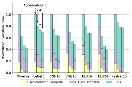
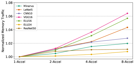
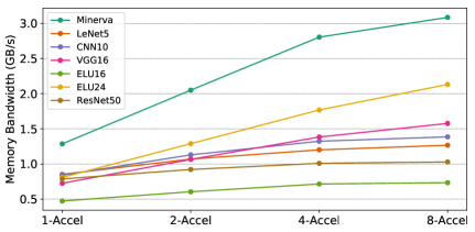
Figure 12 shows how performance of multi-accelerator systems scales with accelerator count. As expected, accelerator compute time speedup is consistent with the increase in available processing units. It continues until we saturate the available tile-level parallelism, which naturally occurs earlier for smaller networks than larger ones. Increasing accelerator count also means increasing total DRAM bytes transferred because some data will need to be broadcast to all PEs, but as Figure 13a shows, this effect is small in the context of the entire workload, with at most a 6% increase in overall traffic. On the other hand, Figure 13b shows that multiple accelerators are also able to make better use of the available memory bandwidth. Overall, data transfer time drops by around 60% on average. Together, with eight accelerators in the system, end-to-end latency improves by between 20-60% over a single-accelerator system. This case study demonstrates how SMAUG can clearly illuminate the overall performance bottlenecks in DNN performance: by the time we reach eight accelerators, compute time is negligible compared to data transfer time and software stack time, and therefore those are the next components to optimize.
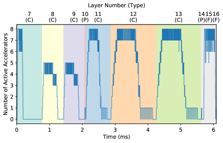
When debugging bottlenecks in DNN inference, it is useful to inspect per-operation performance or performance between two particular operations. With SMAUG, we can generate an execution timeline of important events for users to visualize. For example, Figure 14 shows the accelerator utilization for the last ten layers of VGG16, when the system has eight accelerators in total. These layers contain the largest six convolutional layers by number of parameters, 2 pooling layers (2x2), and 2 fully-connected layers (512 and 10 neurons each). The timeline illustrates several opportunities for further optimization, which we summarize below.
Work balancing for higher accelerator utilization. The timeline shows that layers 8 and 9 are not fully utilizing all the accelerators in the system because for this accelerator, the runtime scheduler only supports in-place reduction of partial products along the channel dimension, so all the tiles whose partial products must be reduced are put onto the same accelerator’s command queue. Then for this layer shape, there are only five output tiles (i.e. independent streams of work), so only five accelerators are used. It is possible to evenly distribute work across all workers, which would require the runtime scheduler to support inter-accelerator reduction. Overall, the runtime scheduler in SMAUG does a good job in exploiting tile-level parallelism in the DNN; we leave further optimization of the scheduler for future work.
Accelerating inter-layer tiling operations. The timeline shows that on Layer 7, the accelerator finishes computation very quickly, followed by a long period of CPU activity. This is the CPU performing “data finalization”: gathering all the output tiles from the accelerators and rearranging them into a single tensor (effectively “untiling” the tensor), because the next layer will likely need different input tile shapes. Ways to optimize this includes adjusting tiling shapes to maximize regions for contiguous memcpys (see Figure 6) and distributing the work across multiple CPUs to increase task-level parallelism and memory bandwidth utilization, which is the subject of the next section.
IV-C Improving Software Stack: Multithreaded Data Management
After all the effort spent optimizing core kernels like matrix-multiply and convolution, the performance bottleneck shifts to the cost of preparing data for use, and since this preparation is typically part of the software framework, the overhead is exaggerated in comparison to the accelerated kernels. This is not specific to SMAUG; on industry-grade recommendation models, data preparation, other framework native operations, and synchronization can take up anywhere from 10 to over 70% of inference latency [8, 9]. In this case study, we look at ways to reduce this overhead.
We break down the execution time of the software stack into three parts: data preparation, data finalization, and other software activities. Data preparation includes layout transformations, in which the dimensions of a tensor are either rearranged (e.g. NCHW to NHWC) or flattened, and tensor tiling, which copies non-contiguous logical regions of one tensor into contiguous smaller tensors which can then be directly transferred to the accelerator for computation. As a result, when accelerators finish their work, their output tensors are also tiled, which must now be “untiled” to obtain the final output tensor. We refer to this untiling operation as data finalization. Finally, other software activities include tasks like control flow management, memory management, various glue logic, and thread synchronization.
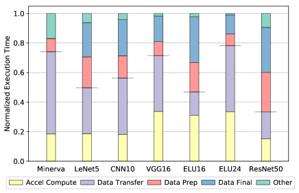
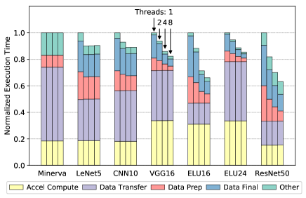
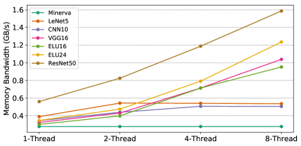
Figure 15 shows that on the baseline system, data preparation and finalization account for 85% of the software stack time, so there is ample room for improvement. As with the previous section, we attack this problem through tile-level parallelism. We use SMAUG’s thread pool (see Section II-E3) to distribute data preparation and finalization tasks across multiple threads. Each thread is responsible for copying data to/from a set of tiles. The baseline system has already accounted for the cost of tiling transformations when determining the best available tiling strategy.
With multithreaded tiling, we can achieve up to 3- speedup on data preparation/finalization with eight threads, as shown in Figure 16, resulting in an end-to-end latency reduction of up to 37%. This speedup is primarily due to an increase in memory bandwidth utilization when multiple threads are active. Figure 17 shows the memory bandwidth usage during the data preparation and gathering phases of the multithreaded software stack. On large networks like ResNet50, which have a lot of tiles, multiple threads increases bandwidth utilization by and leads to a speedup on data preparation and finalization tasks, while smaller networks like Minerva don’t have enough tile-level parallelism for multi-threading to exploit.
IV-D Overall Combined Speedup
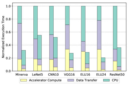
Figure 18 summarizes the combined effect of the three case studies on a single forward pass through all the networks. The SoC uses the ACP interface with eight accelerators and eight threads in the software stack. Overall latency drops by between 45% on LeNet5 to as much as 80% on ELU24 (1.8- speedup), all without changing any part of the accelerator microarchitecture. This is a demonstration of the power of SMAUG applied to system-level performance optimization of DNN workloads.
V Optimizing A Camera-Powered Deep Learning Pipeline
In recent years, it has become increasingly common to attach deep learning models at the end of other applications. One notable such application uses the camera pipeline with a DNN to perform real-time tasks such as object classification, detection, segmentation and labeling. In this study, we demonstrate how SMAUG can also model this kind of application and enable hardware-software co-design for better performance and energy efficiency.
The camera pipeline is a long series of spatial linear and non-linear filters and transforms to convert the raw output of the image sensor into a realistic RGB representation. The sensor itself sits behind a Bayer color filter, so each individual photodiode only captures light from one primary color (RGB). As a result, the output of the sensor is an array of pixel values, each representing the intensity of a single color. The process that estimates the original color of each pixel from this raw image is called demosaicing. The subsequent image processing then proceeds through many more processing steps, like white balance correction, color space conversion, chroma subsampling, and more. Finally, the image is compressed in a lossy format (e.g. JPEG), which preserves low frequency details that human eyes are sensitive to while removing imperceptible high frequency information [41].
To construct such a camera vision pipeline, we integrate the complete camera pipeline implementation shipped with Halide [42] into SMAUG and simulate it as a single process running on the CPU. The camera pipeline transforms raw data recorded by camera sensors into usable 720p images, including several stages: hot pixel suppression, deinterleaving, demosaicing, white balancing and sharpening. Modern image sensors use multi-megapixel resolutions, but that resolution is often not necessary for DNNs, in this study, we feed 720p images through the camera pipeline, then downsample it to the size required by the DNN. For real-time applications, frame-time is a more representative metric of responsiveness than throughput, so assuming the application targets 30 FPS throughput, each frame must complete within 33 ms. The baseline system configuration we use is the same as the earlier case studies, except that to show the accelerator variety in SMAUG, we use the systolic array model (a cycle-level timing model written as a native gem5 object), configured as an 8x8 PE array instead of the NVDLA-inspired model.
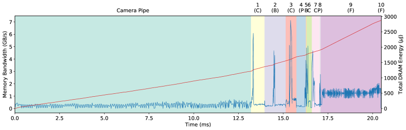
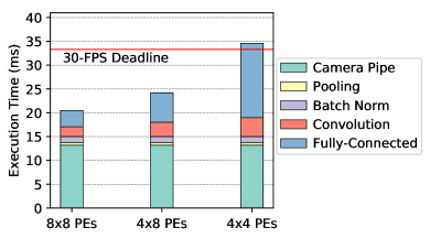
Figure 19 shows the execution timeline for the camera vision pipeline, using the CNN10 network. With SMAUG, we can produce a trace of memory bandwidth utilization and total memory energy consumed during the application. In this case, the overall pipeline takes 20.5 ms to finish (13.2ms of camera pipeline and 7.3ms of DNN), and memory energy consumption is well balanced between the CPU (43%) and accelerator (57%). The slack time (12.8 ms) before the frame deadline means that in energy or chip area constrained scenarios, we could afford to use an even smaller systolic array. As shown in Figure 20, reducing the PE array in half (4x8) increases the DNN latency to 11.0 ms, which still meets the frame-time limits. However, further decreasing the PEs to a 4x4 array results in an overall latency of 34.6 ms, violating the real-time constraint. Most of this extra latency comes from the final classifier layer.
VI Related Work
Simulation frameworks. SoC-accelerator simulators usually require the user to implement the accelerators in RTL or using HLS tools [43, 44, 45, 46, 47, 48]. Centrifuge proposes a prototyping methodology that leverages HLS to generate accelerator SoCs and deploy them to FPGAs [43]. PARADE combines HLS with gem5 for full-system simulation [44]. GemDroid couples gem5 with the Android Emulator and integrates various hardware IP models to enable SoC-level simulation [47]. The heavy reliance on RTL implementation significantly increases the algorithm-to-solution time, even with HLS tools. In contrast, SMAUG builds on top of gem5-Aladdin, which uses a pre-RTL approach to accurately model the power, performance, and area of accelerator designs.
Table I lists a selection of deep learning research frameworks. Some are end-to-end systems, like TensorFlow [10] or TVM [17], but they either do not support simulation or require detailed pipeline models or RTL. Other tools focus on exploring dataflows and efficiently map DNN kernels to FPGAS or ASICs [49, 14, 15, 16, 50, 51]. These often implement a component library or optimized template designs for hardware optimization, but with a heavy focus on optimizing the accelerator, they can’t evaluate networks end-to-end, leaving a lot of design opportunities unexplored. While all of these tools have their place in the deep learning research infrastructure landscape, they do not provide SMAUG’s capability of enabling end-to-end early-stage design space exploration of the SoC as well as the accelerator.
Due to the regularity of DNNs, there are simulation tools that apply analytical models for DNN performance analysis [18, 48]. SCALE-Sim [18] models the systolic array accelerator with a variety of dataflows, each based on a different analytical model. While analytical models are fast for performance estimation, they cannot capture dynamic runtime behavior. SMAUG, however, captures both accelerator and system level activities while maintaining fast simulation speed with the accurate sampling support.
DNN Accelerator Designs. There has been an incredible amount of interest in DNN hardware acceleration. Broadly speaking, the architecture community has focused on designing efficient dataflows to maximize local reuse of data and functional unit utilization [1, 4, 5, 7, 2, 6, 52, 53], exploit model sparsity and data quantization [54, 55, 56, 3, 57, 58, 21], map DNN accelerators to FPGAs [59, 60, 61], explore alternative computation and memory technologies [62, 63], or use multi-chip-module package integration to achieve high-performance DNN inference [64]. Although these works are highly relevant, these papers do not address end-to-end performance evaluation or between-the-layer operations, like data layout transformations.
SoC-Accelerator Interfacing. Over the years, there have been a few publications investigating SoC-accelerator interfacing and interactions in a variety of contexts, such as CoRAMs [65], Layer [66], and Google mobile system workloads [67]. A few recent works have considered interfacing between the SoC and accelerators [68, 69, 70]. A handful of other works have used the ARM accelerator coherency port for tighter coupling between CPU and accelerators, albeit not in the context of DNNs [71, 72].
VII Acknowledgement
This work was supported in part by the U.S. Government, under the DARPA DSSoC program. This work was also supported in part by the Semiconductor Research Corporation, NSF grant CNS-1718160, and Intel.
VIII Conclusion
This paper demonstrates the critical importance of evaluating full-stack performance of a hardware accelerated computing task like neural network inference. Recent years have brought great advances in accelerator design and efficient DNN dataflows, but several important components of overall performance, like data transformation and movement cost and software framework overheads, have received far less attention, partly because of a lack of suitable research infrastructure. We developed SMAUG, a DNN framework that can be simulated in a cycle-level SoC simulator, and demonstrate how it can be used to optimize end-to-end performance on a wide range of DNNs to achieve between 1.8-5 speedup by optimizing SoC-accelerator interfaces, exploiting multi-accelerator systems, and optimizing the software stack. Since SMAUG provides architects with a straightforward approach to simulate complex full-stack workloads, we hope it will spur renewed interest in broader optimization of end-to-end performance in DNN hardware studies.
References
- [1] N. P. Jouppi, C. Young, N. Patil, D. Patterson, G. Agrawal, R. Bajwa, S. Bates, S. Bhatia, N. Boden, A. Borchers et al., “In-datacenter performance analysis of a tensor processing unit,” in ISCA, 2017.
- [2] Y.-H. Chen, T. Krishna, J. Emer, and V. Sze, “Eyeriss: An Energy-Efficient Reconfigurable Accelerator for Deep Convolutional Neural Networks,” in ISSCC, 2016.
- [3] P. Judd, J. Albericio, T. Hetherington, T. M. Aamodt, and A. Moshovos, “Stripes: Bit-serial deep neural network computing,” in MICRO, 2016.
- [4] P. Chi, S. Li, C. Xu, T. Zhang, J. Zhao, Y. Liu, Y. Wang, and Y. Xie, “Prime: a novel processing-in-memory architecture for neural network computation in reram-based main memory,” in ISCA, 2016.
- [5] S. Liu, Z. Du, J. Tao, D. Han, T. Luo, Y. Xie, Y. Chen, and T. Chen, “Cambricon: An instruction set architecture for neural networks,” in ISCA, 2016.
- [6] M. Alwani, H. Chen, M. Ferdman, and P. Milder, “Fused-layer cnn accelerators,” in MICRO, 2016.
- [7] C. Ding, S. Liao, Y. Wang, Z. Li, N. Liu, Y. Zhuo, C. Wang, X. Qian, Y. Bai, G. Yuan et al., “Circnn: accelerating and compressing deep neural networks using block-circulant weight matrices,” in MICRO, 2017.
- [8] Y. E. Wang, C.-J. Wu, X. Wang, K. Hazelwood, and D. Brooks, “Exploiting parallelism opportunities with deep learning frameworks,” 2019.
- [9] J. Park, M. Naumov, P. Basu, S. Deng, A. Kalaiah, D. Khudia, J. Law, P. Malani, A. Malevich, S. Nadathur, J. Pino, M. Schatz, A. Sidorov, V. Sivakumar, A. Tulloch, X. Wang, Y. Wu, H. Yuen, U. Diril, D. Dzhulgakov, K. Hazelwood, B. Jia, Y. Jia, L. Qiao, V. Rao, N. Rotem, S. Yoo, and M. Smelyanskiy, “Deep learning inference in facebook data centers: Characterization, performance optimizations and hardware implications,” 2018.
- [10] M. Abadi, P. Barham, J. Chen, Z. Chen, A. Davis, J. Dean, M. Devin, S. Ghemawat, G. Irving, M. Isard et al., “Tensorflow: A system for large-scale machine learning,” in OSDI, 2016.
- [11] N. Ketkar, “Introduction to pytorch,” in Deep learning with python. Springer, 2017.
- [12] Y. Jia, E. Shelhamer, J. Donahue, S. Karayev, J. Long, R. Girshick, S. Guadarrama, and T. Darrell, “Caffe: Convolutional architecture for fast feature embedding,” in Proceedings of the 22nd ACM international conference on Multimedia, 2014.
- [13] T. Chen, M. Li, Y. Li, M. Lin, N. Wang, M. Wang, T. Xiao, B. Xu, C. Zhang, and Z. Zhang, “Mxnet: A flexible and efficient machine learning library for heterogeneous distributed systems,” arXiv preprint arXiv:1512.01274, 2015.
- [14] H. Sharma, J. Park, E. Amaro, B. Thwaites, P. Kotha, A. Gupta, J. K. Kim, A. Mishra, and H. Esmaeilzadeh, “Dnnweaver: From high-level deep network models to fpga acceleration,” in the Workshop on Cognitive Architectures, 2016.
- [15] X. Zhang, J. Wang, C. Zhu, Y. Lin, J. Xiong, W.-m. Hwu, and D. Chen, “Dnnbuilder: an automated tool for building high-performance dnn hardware accelerators for fpgas,” in Proceedings of the International Conference on Computer-Aided Design. ACM, 2018.
- [16] R. Venkatesan, Y. S. Shao, M. Wang, J. Clemons, S. Dai, M. Fojtik, B. Keller, A. Klinefelter, N. Pinckney, P. Raina et al., “Magnet: A modular accelerator generator for neural networks,” in ICCAD, 2019.
- [17] T. Chen, T. Moreau, Z. Jiang, L. Zheng, E. Q. Yan, H. Shen, M. Cowan, L. Wang, Y. Hu, L. Ceze, C. Guestrin, and A. Krishnamurthy, “TVM: an automated end-to-end optimizing compiler for deep learning,” in USENIX OSDI, 2018.
- [18] A. Samajdar, Y. Zhu, P. N. Whatmough, M. Mattina, and T. Krishna, “SCALE-sim: Systolic CNN accelerator,” CoRR, 2018. [Online]. Available: http://arxiv.org/abs/1811.02883
- [19] M. Sun, P. Zhao, Y. Wang, N. Chang, and X. Lin, “Hsim-dnn: Hardware simulator for computation-, storage-and power-efficient deep neural networks,” in Proceedings of the 2019 on Great Lakes Symposium on VLSI. ACM, 2019.
- [20] Y. S. Shao, S. L. Xi, V. Srinivasan, G.-Y. Wei, and D. Brooks, “Co-designing accelerators and soc interfaces using gem5-aladdin,” in MICRO, 2016.
- [21] B. Reagen, P. Whatmough, R. Adolf, S. Rama, H. Lee, S. K. Lee, J. M. Hernandez-Lobato, G.-Y. Wei, and D. Brooks, “Minerva: Enabling Low-Power, Highly-Accurate Deep Neural Network Accelerators,” in ISCA, 2016.
- [22] Y LeCun and L. Bottou and Y. Bengio and P. Haffner, “Gradient-based learning applied to document recognition,” in Proceedings of the IEEE, 1998.
- [23] Sergey Zagoruyko, “Torch Blog: 92.45 on CIFAR10 in Torch,” 2015. [Online]. Available: {https://torch.ch/blog/07/30/cifar.html}
- [24] S. H. Djork-Arne Clevert, Thomas Underthiner, “Fast and accurate deep network learning by exponential linear units (elus),” in ICLR, 2016.
- [25] K. He, X. Zhang, S. Ren, and J. Sun, “Deep residual learning for image recognition,” in Proceedings of the IEEE conference on computer vision and pattern recognition, 2016.
- [26] V. J. Reddi, C. Cheng, D. Kanter, P. Mattson, G. Schmuelling, C.-J. Wu, B. Anderson, M. Breughe, M. Charlebois, W. Chou, R. Chukka, C. Coleman, S. Davis, P. Deng, G. Diamos, J. Duke, D. Fick, J. S. Gardner, I. Hubara, S. Idgunji, T. B. Jablin, J. Jiao, T. S. John, P. Kanwar, D. Lee, J. Liao, A. Lokhmotov, F. Massa, P. Meng, P. Micikevicius, C. Osborne, G. Pekhimenko, A. T. R. Rajan, D. Sequeira, A. Sirasao, F. Sun, H. Tang, M. Thomson, F. Wei, E. Wu, L. Xu, K. Yamada, B. Yu, G. Yuan, A. Zhong, P. Zhang, and Y. Zhou, “Mlperf inference benchmark,” 2019.
- [27] Norman P. Jouppi and Andrew B. Kahng and Naveen Muralimanohar and Vaishav Srinivas, “CACTI-IO: CACTI with Off-Chip Power-Area-Timing Models,” IEEE Transactions on VLSI Systems, vol. 23, 2015.
- [28] Karthik Chandrasekar, Christian Weis, Yonghui Li, Sven Goossens, Matthias Jung, Omar Naji, Benny Akesson, Norbert Wehn, and Kees Goossens, “DRAMPower: Open-Source DRAM Power and Energy Estimation Tool,” http://drampower.info.
- [29] Mobile LPDDR4 SDRAM, Micron Technology, 2014.
- [30] S. Kumar, A. Shriraman, and N. Vedula, “Fusion: Design Tradeoffs in Coherent Cache Hierarchies for Accelerators,” in ISCA, 2015.
- [31] J. Alsop, M. D. Sinclair, and S. V. Adve, “Spandex: A flexible interface for efficient heterogeneous coherence,” ISCA, 2018.
- [32] L. E. Olson, J. Power, M. D. Hill, and D. A. Wood, “Border Control: Sandboxing Accelerators,” in MICRO, 2015.
- [33] L. E. Olson, M. D. Hill, and D. A. Wood, “Crossing guard: Mediating host-accelerator coherence interactions,” ASPLOS, 2017.
- [34] J. Alsop, M. D. Sinclair, S. Bharadwaj, A. Dutu, A. Gutierrez, O. Kayiran, M. LeBeane, S. Puthoor, X. Zhang, T. T. Yeh et al., “Optimizing gpu cache policies for mi workloads,” arXiv preprint arXiv:1910.00134, 2019.
- [35] AMD, “Compute Cores,” Tech. Rep., 2014. [Online]. Available: www.amd.com/computecores
- [36] M. Harris, “Unified Memory in CUDA 6,” 2013. [Online]. Available: https://devblogs.nvidia.com/parallelforall/unified-memory-in-cuda-6/
- [37] B. Pichai, L. Hsu, and A. Bhattacharjee, “Architectural support for address translation on gpus designing memory management units for cpu/gpus with unified address spaces,” in ASPLOS, 2014.
- [38] J. Power, A. Basu, J. Gu, S. Puthoor, B. M. Beckmann, M. D. Hill, S. K. Reinhardt, and D. A. Wood, “Heterogeneous System Coherence for Integrated CPU-GPU Systems,” in MICRO, 2013.
- [39] J. Power, M. D. Hill, and D. A. Wood, “Supporting x86-64 address translation for 100s of gpu lanes,” in HPCA, 2014.
- [40] A. Tabbakh, X. Qian, and M. Annavaram, “G-tsc: Timestamp based coherence for gpus,” in 2018 IEEE International Symposium on High Performance Computer Architecture (HPCA). IEEE, 2018.
- [41] K. Fatahalian, “A camera image processing pipeline,” 2011. [Online]. Available: http://www.cs.cmu.edu/afs/cs/academic/class/15869-f11/www/lectures/16_camerapipeline1.pdf
- [42] J. Ragan-Kelley, C. Barnes, A. Adams, S. Paris, F. Durand, and S. Amarasinghe, “Halide: a language and compiler for optimizing parallelism, locality, and recomputation in image processing pipelines,” ACM SIGPLAN Notices, 2013.
- [43] Q. Huang, C. Yarp, S. Karandikar, N. Pemberton, B. Brock, L. Ma, G. Dai, R. Quitt, K. Asanovic, and J. Wawrzynek, “Centrifuge: Evaluating full-system hls-generated heterogeneous-accelerator socs using fpga-acceleration,” in ICCAD, 2019.
- [44] J. Cong, Z. Fang, M. Gill, and G. Reinman, “PARADE: A Cycle-Accurate Full-System Simulation Platform for Accelerator-Rich Architectural Design and Exploration,” in ICCAD, 2015.
- [45] T. Liang, L. Feng, S. Sinha, and W. Zhang, “Paas: A system level simulator for heterogeneous computing architectures,” in 2017 27th International Conference on Field Programmable Logic and Applications (FPL). IEEE, 2017.
- [46] L. Piccolboni, P. Mantovani, G. Di Guglielmo, and L. P. Carloni, “Broadening the exploration of the accelerator design space in embedded scalable platforms,” in 2017 IEEE High Performance Extreme Computing Conference (HPEC). IEEE, 2017.
- [47] N. Chidambaram Nachiappan, P. Yedlapalli, N. Soundararajan, M. T. Kandemir, A. Sivasubramaniam, and C. R. Das, “Gemdroid: a framework to evaluate mobile platforms,” ACM SIGMETRICS Performance Evaluation Review, vol. 42, 2014.
- [48] Synopsys Inc., “Synopsys Platform Architect,” https://www.synopsys.com/verification/virtual-prototyping/platform-architect.html/.
- [49] C. Zhang, P. Li, G. Sun, Y. Guan, B. Xiao, and J. Cong, “Optimizing fpga-based accelerator design for deep convolutional neural networks,” in Proceedings of the 2015 ACM/SIGDA International Symposium on Field-Programmable Gate Arrays. ACM, 2015.
- [50] Y. S. S. Y.-H. C. V. A. Y. A. M. R. V. B. K. S. W. K. Angshuman Parashar, Priyanka Raina and J. Emer, “Timeloop: A systematic approach to dnn accelerator evaluation,” in ISPASS, 2019.
- [51] Wu, Yannan N. and Emer, Joel S. and Sze, Vivienne, “Accelergy: An Architecture-Level Energy Estimation Methodology for Accelerator Designs,” in IEEE/ACM International Conference On Computer Aided Design (ICCAD), 2019.
- [52] W. Lu, G. Yan, J. Li, S. Gong, Y. Han, and X. Li, “Flexflow: A flexible dataflow accelerator architecture for convolutional neural networks,” in HPCA, 2017.
- [53] H. Kwon, A. Samajdar, and T. Krishna, “Maeri: Enabling flexible dataflow mapping over dnn accelerators via reconfigurable interconnects,” in ASPLOS, 2018.
- [54] H. K. V. N.-S. S. D. D. B. K. T. K. Eric Qin, Ananda Samajdar, “SIGMA: A Sparse and Irregular GEMM Accelerator with Flexible Interconnects for DNN Training,” in HPCA, 2019.
- [55] M. Zhu, T. Zhang, Z. Gu, and Y. Xie, “Sparse tensor core: Algorithm and hardware co-design for vector-wise sparse neural networks on modern gpus,” in Proceedings of the 52Nd Annual IEEE/ACM International Symposium on Microarchitecture, 2019.
- [56] Xiaowei Wang and Jiecao Yu and Charles Augustine and Ravi Iyer and Reetuparna Das, “Bit Prudent In-Cache Acceleration of Deep Convolutional Neural Networks,” in HPCA, 2019.
- [57] A. Parashar, M. Rhu, A. Mukkara, A. Puglielli, R. Venkatesan, B. Khailany, J. S. Emer, S. W. Keckler, and W. J. Dally, “SCNN: an accelerator for compressed-sparse convolutional neural networks,” in ISCA, 2017.
- [58] S. Han, X. Liu, H. Mao, J. Pu, A. Pedram, M. Horowitz, and W. Dally, “EIE: Efficient inference engine on compressed deep neural network,” in ISCA, 2016.
- [59] Y. Guan, H. Liang, N. Xu, W. Wang, S. Shi, X. Chen, G. Sun, W. Zhang, and J. Cong, “FP-DNN: an automated framework for mapping deep neural networks onto FPGAs with RTL-HLS hybrid templates,” in FCCM, 2017.
- [60] C. Wang, L. Gong, Q. Yu, X. Li, Y. Xie, and X. Zhou, “DLAU: A scalable deep learning accelerator unit on FPGA,” IEEE Trans. on CAD of Integrated Circuits and Systems, vol. 36, 2017.
- [61] X. Wei, Y. Liang, and J. Cong, “Overcoming data transfer bottlenecks in fpga-based DNN accelerators via layer conscious memory management,” in DAC, 2019.
- [62] A. Shafiee, A. Nag, N. Muralimanohar, R. Balasubramonian, J. P. Strachan, M. Hu, R. S. Williams, and V. Srikumar, “Isaac: A convolutional neural network accelerator with in-situ analog arithmetic in crossbars,” in ISCA, 2016.
- [63] P. Wang, Y. Ji, C. Hong, Y. Lyu, D. Wang, and Y. Xie, “SNrram: An Efficient Sparse Neural Network Computation Architecture Based on Resistive Random-Access Memory,” in DAC, 2018.
- [64] Y. S. Shao, J. Clemons, R. Venkatesan, B. Zimmer, M. Fojtik, N. Jiang, B. Keller, A. Klinefelter, N. R. Pinckney, P. Raina, S. G. Tell, Y. Zhang, W. J. Dally, J. S. Emer, C. T. Gray, B. Khailany, and S. W. Keckler, “Simba: Scaling deep-learning inference with multi-chip-module-based architecture,” in MICRO, 2019.
- [65] E. S. Chung, J. C. Hoe, and K. Mai, “Coram: An in-fabric memory architecture for fpga-based computing,” in FPGA, 2011.
- [66] Y. Kim, J. Kim, D. Chae, D. Kim, and J. Kim, “ulayer: Low latency on-device inference using cooperative single-layer acceleration and processor-friendly quantization,” in Proceedings of the Fourteenth EuroSys Conference 2019, 2019.
- [67] A. Boroumand, S. Ghose, Y. Kim, R. Ausavarungnirun, E. Shiu, R. Thakur, D. Kim, A. Kuusela, A. Knies, P. Ranganathan, and O. Mutlu, “Google Workloads for Consumer Devices: Mitigating Data Movement Bottlenecks,” in ASPLOS, 2018.
- [68] Y. Zhu, A. Samajdar, M. Mattina, and P. Whatmough, “Euphrates: Algorithm-soc co-design for low-power mobile continuous vision,” in Proceedings of the 45th Annual International Symposium on Computer Architecture, ser. ISCA ’18. Piscataway, NJ, USA: IEEE Press, 2018. [Online]. Available: https://doi.org/10.1109/ISCA.2018.00052
- [69] M. Buckler, P. Bedoukian, S. Jayasuriya, and A. Sampson, “Exploiting temporal redundancy in live computer vision,” ISCA, 2018.
- [70] Y. Feng, P. N. Whatmough, and Y. Zhu, “ASV: accelerated stereo vision system,” in MICRO, 2019.
- [71] M. Sadri, C. Weis, N. Wehn, and L. Benini, “Energy and performance exploration of accelerator coherency port using xilinx zynq,” in FPGAWorld, 2013.
- [72] T. Moreau, M. Wyse, J. Nelson, A. Sampson, H. Esmaeilzadeh, L. Ceze, and M. Oskin, “Snnap: Approximate computing on programmable socs via neural acceleration,” in HPCA, 2015.