Reorienting Objects in 3D Space Using Pivoting
Abstract
We consider the problem of reorienting a rigid object with arbitrary known shape on a table using a two-finger pinch gripper. Reorienting problem is challenging because of its non-smoothness and high dimensionality. In this work, we focus on solving reorienting using pivoting, in which we allow the grasped object to rotate between fingers. Pivoting decouples the gripper rotation from the object motion, making it possible to reorient an object under strict robot workspace constraints. We provide detailed mechanical analysis to the 3D pivoting motion on a table, which leads to simple geometric conditions for its stability. To solve reorienting problems, we introduce two motion primitives: pivot-on-support and roll-on-support, and provide an efficient hierarchical motion planning algorithm with the two motion primitives to solve for the gripper motions that reorient an object between arbitrary poses. To handle the uncertainties in modeling and perception, we make conservative plans that work in the worst case, and propose a robust control strategy for executing the motion plan. Finally we discuss the mechanical requirements on the robot and provide a ”two-phase” gripper design to implement both pivoting grasp and firm grasp. We demonstrate the effectiveness of our method in simulations and multiple experiments. Our algorithm can solve more reorienting problems with fewer making and breaking contacts, when compared to traditional pick-and-place based methods.
Index Terms:
Reorienting, regrasping, pivoting, motion planning.I INTRODUCTION
There are many things roboticists can learn from human manipulation, even when humans do not take advantage of the dexterity of the hand. For example, a human using the thumb and index finger in a pinch grasp can easily outperform an industrial robot with a pinch gripper in tasks such as picking and reorienting objects. Although the end effectors are similar, humans are better in at least the following two important ways. First, humans utilize extrinsic dexterity [14] such as gravity, inertia forces and extrinsic contact forces in addition to joint forces. Second, human hands are compliant. For example, we can hold and manipulate an object while leaning it on a table without crushing anything. As a result, human hands have a larger repertoire of motions to use.
I-A The Reorienting Problem
The frequent appearance of making and breaking contacts in extrinsic dexterity introduces non-smooth mechanics and discrete decision variables. Together with the high dimensionality of the system (object plus robot), they make it challenging to find solutions fast and reliably for mainstream planning and control methods, such as trajectory optimization, sampling based planning or reinforcement learning.
One such example is object reorienting: quickly move an object between different 3D orientations. The reorienting problem is common in industrial applications such as polishing, soldering and assembling, where an object undergoes multiple procedures in sequence; and also home applications such as tidying a table. In these scenarios, the object may have a complicated shape. The robot needs to decide how to manipulate the object (pushing, grasping, etc), while staying within a constrained workspace.
For robots with simple grippers, traditional methods for reorienting simplify planning by only using pick-and-place motion [22, 23, 37, 35, 12, 40]. In pick-and-place, the manipulator rotates the object by grasping it firmly, then places it at a different stable pose. The process may repeat a few times before the goal pose is reached. The planning problem becomes totally kinematic and easier to solve. However, pick-and-place brings limits on the robot motion. For example, the robot gripper must rotate along with the object, which is impossible in a limited workspace and takes unnecessarily long time.
I-B Motion Primitives for Reorienting
Although pick-and-place has its limitations, it inspires us to solve the reorienting by decomposing it into smaller, well-defined, solvable problems. These sub-problems describe parametrized motions and are designed to be easily solvable, we call them motion primitives. For example, single pick-and-place with one grasp is a motion primitive for reorienting. Once we can solve the motion primitive, we can further solve the original problem by run the motion primitive several times with suitable parameters. This step is high level and has much fewer variables to consider, so the computation time is reduced.
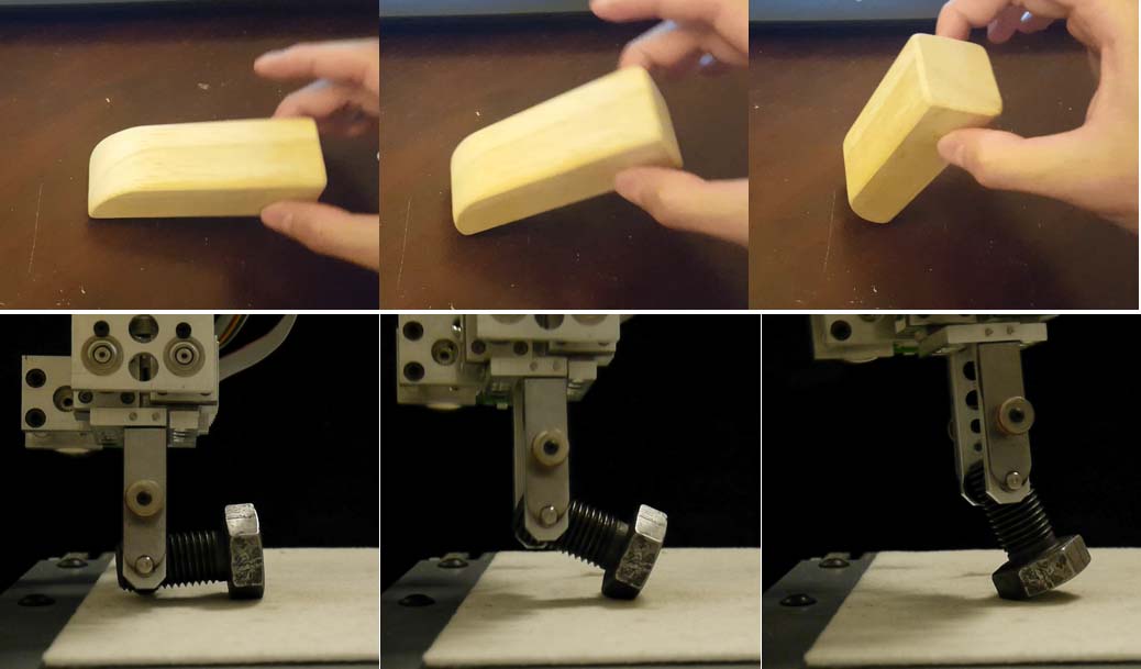
In this work, we design better motion primitives for reorienting objects by observing human motion. Even with a two finger pinch grasp, a human hand can reorient an object more elegantly with less hand and arm motion than pick-and-place reorienting. The key difference is that human hands allow and utilize slips between the object and fingertips. We summarize this behavior as a new motion primitive: pivot-on-support. The object is pinch-grasped, but can rotate passively about the grasp axis. Meanwhile the object is in contact with the table under gravity. The motion primitive brings several benefits. Firstly, the gripper motion is decoupled from the rotation of the grasped object, making it possible to perform reorienting under stricter workspace constraints. For the same reason, there exist more efficient solutions for robot motion. Secondly, the contact on the table balance the object weight, so we can use the quasi-static assumption to simplify the modeling. pivot-on-support is more flexible than pick-and-place, yet it is easier to control than those more dynamic motion primitives such as throwing and catching [14], pivoting with gravity [39] or inertia force [33, 16].
Note that pivot-on-support is not always stable. A pivot grasp does not form a force closure; the object may break the contact with the table and fall over under gravity. To continue reorienting the object when pivoting is unstable, human hand would stop pivoting and switch to a firm non-slip grasp till pivoting becomes stable again. We use the non-slip grasp mode as another motion primitive for our planner, call it roll-on-support. As the name suggests, we still maintain the contact with the table as the object rotates, so as to have a smooth transition between the two motion primitives.
We provide an algorithm to solve reorienting efficiently using the two motion primitives. The algorithm takes as input an object with arbitrary shape, as well as an arbitrary 3D initial pose and goal pose. At low level the algorithm plans a gripper trajectory that alternates between the two motion primitives to move the object, given one grasp location. On top of that, it performs graph search to plan multi-step reorientings and pick the best grasp locations. By analyzing the model of pivoting, we provide simple conditions to quickly check if a pivoting pose is stable, which enables fast computing. To further accelerate the online computation, we off-load grasp point selection and some collision checking off-line. Then our hierarchical approach can find a solution or declare infeasibility for a new problem in a couple of seconds. The off-line computation takes several minutes and only needs to be done once per object.
I-C Robustness from Planning, Control and Hardware
The algorithm needs to know the object shape and mass property, which can be hard to obtain accurately. We do robust planning by modeling the uncertainties as bounded errors. Then the algorithm computes conservative plans that work in the worst case.
Still, robust planning alone is not enough for ensuring successful experiments. Picking a perfect value for an uncertainty bound is a tricky trade-off between robustness and feasibility. Instead of carefully tuning uncertainty parameters, we do planning using rough parameters then execute the motion plan robustly with hybrid force-velocity control, which reduces unexpected slips and robot crashes. We demonstrate our planning and execution scheme in experiments with several real-life objects.
Our algorithm assumes the gripper hardware to be capable of implementing the two motion primitives. Specifically, in pivoting the object should rotate without translational slips between fingers. In this work we discuss the requirements and design principles for such grippers, and provide one simple ”two-phase” finger design that can switch between the two motion primitives.
To demonstrate our method, we firstly compare our method with pick-and-place based reorienting method in simulations, and report statistics including number of solved problems and computation time. Then we demonstrate the motion plans in experiments with multiple objects.
This paper is and extension of our previous work on reorienting [17]. The contributions of this work are:
-
•
Mechanical analysis of pivoting that extends the planar analysis in [17] to 3D motion;
-
•
Fast and robust motion planning for reorienting in 3D, where the gripper motion planning problem is formulated as a Quadratic Programming (QP).
-
•
Hardware design of a two-phase gripper.
-
•
Simulation and experiment verifications.
II RELATED WORK
II-A Generic Motion Planning
Theoretically, many existed generic motion planning methods can handle the problem of manipulating an rigid object with a gripper. However, none of them has satisfying performance. Sampling based planning methods find a solution by building a tree or a graph of states. They can guarantee the existence of solution given enough time [41]. However, the process is usually too long, especially for a system with more than 6 DOFs (object pose and gripper pose in 3D space). Trajectory optimization suffers from the non-smoothness and high dimensionality. Gradient doesn’t exist, which disables powerful continuous solvers. Many work use linear complimentary constraints (LCP) to model the contact as continuous constraints, however, these constraints make the optimization problem close to ill-conditioned [30]. It’s sensitive to the choice of initial trajectory, and it is hard to further optimize a solution. Existing methods often rely on overly simplified physics model and only demonstrate results in simulations [26, 27, 38], and still take minutes to find a solution. Reinforcement learning has also shown ability to solve a range of manipulation problems [29, 21]. However, one basic assumption in reinforcement learning is that sampling actions randomly can explore useful actions. This is only true for tasks that are generally stable. It is almost impossible for a task like flipping an object by pivoting. The sampled action has to stay on the right sub-manifold for some time steps, otherwise the object will drop and the exploration go back to the beginning.
II-B Object Reorienting
Work on pick-and-place reorienting can date back to 1970s, when Richard Paul used a robot arm and a parallel gripper to pick-and-place a cube in correct orientation [28]. Since 1980s, the mainstream approaches would discretize the whole gripper-object state space with a ”grasp-placement table” [22, 23, 37]. The set of grasps were selected off-line. A motion sequence can be obtained by back chaining from the goal during planning. The approach is then adopted and improved in several ways. Stoeter et al. computed the stable placements of the object and the discretized gripper motion, built the list of ”Grasp-placement-grasp” triples for searching online [35]. Cho et al. stores collision-free states in a lookup table, then find intermediate placement incrementally by querying the table [12]. Wan et al. [40] and Xue et al. [42] utilize graph structure to represent feasible gripper and object poses for efficient online searching. Wan et al. also decompose the search of pick-and-place sequence from the search of grasps for better efficiency. Cao et al. [5, 4] extended the graph structure to consider fixtures of different shapes instead of a plain table. In those work, only stable placements are discretized and stored as entries in the table/nodes on the graph. In our previous work, we extended the graph to consider arbitrary initial and goal object poses, yet maintained a concise graph by leverage more computations in the edges.
II-C Regrasping
Closely related to reorienting, regrasping problems focus on changing the pose of an object with respect to the gripper, while reorienting sets the goal in world frame. Since the transformation between the world frame and the gripper frame is usually known, solutions to the two problems can be used for each other. Dafle et al. demonstrated by hand-coded trajectories that a robot with a simple gripper is able to perform dexterous regraspings by utilizing the extrinsic force resources [14]. Dafle and Rodriguez then used LCP trajectory optimization for planning continuous regrasping motions [7] with extrinsic contacts, as well as sampling-based planning for picking discrete modes [11, 8]. Cruciani et al. extended the graph structure in [40] to consider both release-and-regrasp and prehensile pushing style in hand manipulation. They further extended the method for incremental data to do in hand manipulation with unknown objects [13].
II-D Pivoting as a Motion Primitive
Pivoting has been used as a motion primitive with several kinds of extrinsic actuations, including inertia force [16, 33], gravity [3, 31, 34, 39] as well as extrinsic contact forces [1, 15, 36, 43]. Using inertia force or gravity with grip force control can improve the speed of object motion, however, it poses high requirement on the bandwidth of the robot itself [16, 39, 34]. In [31], the robot lifted up the object and let the object rotate passively under gravity to the desired pose, assuming a suitable grasp along the line of gravity exists. Closely related to our work, Holladay [15] and Terasaki [36] used pivot-on-support for reorienting objects. In both work they analyzed pivoting as a swinging between two stable placements, which require good knowledge of the object inertia model and suitable grasp location.
II-E Gripper Design for Pivoting
There are many different ways to implement pivoting. A parallel/pinch gripper can do pivoting by regulating inertia force [33] and gripping force [39]. However, it’s more robust to do pivoting using a customized finger design that makes it easy to rotate without slipping. The Freddy II robot is probably the first to use a rotating mechanism with active motor control on its fingertips [2]. To make the design compact, passive rotation mechanisms were widely used. Several work used a pair of point contacts on the object to rotate it without slip [1, 15, 10, 9]. People also made face contacts rotatable by adding a rotation shaft to the fingertips of a parallel gripper [6, 36, 16], such that the grasped object can rotate along with the fingertips about the grasp axis.
As we mentioned before, pivoting along is not enough for reorienting objects. The gripper must be able to switch between pivoting and firm grasping. The transition can be done by deforming the soft fingertip [39], but it is hard to model the change of friction force precisely. Terasaki et al. [36] designed a two-phase finger by surrounding a rotational fingertip with a fixed fingertip. The fixed fingertip will contact the object and stop the rotation if the grasp distance decreases. Dafle et al. [10, 9] proposed another two-phase fingertip design that can switch between a point contact and a face contact, so as to transit between pivoting and firm grasping. In this work we provide a new design that combine some of the merits of previous designs.
III PROBLEM DESCRIPTION
Consider a rigid object described by a 3D mesh. Denote as the points on its convex hull measured in the object frame . Its center of mass (COM) in frame is given by . Denote as the position and orientation of the object in world frame . Consider a parallel gripper. The origin of the gripper frame is fixed at the middle point between the two fingertips. The axis points towards the palm, axis parallels the grasp axis. We use and to describe the pose of the gripper frame.
Consider a parallel gripper. Denote as a set of pre-computed grasping locations for the object. We ignore grasp points on corners and only consider grasp points on facets, so a parallel firm grasp is possible. There are plenties of methods available for grasp sampling [32, 40]. Each grasp location is distinguished by two grasp points on the object surface, and . We assume that the grasp points do not change during switching between pivoting and rolling, and that the object rotation axis during pivoting is the line between the two grasp points.
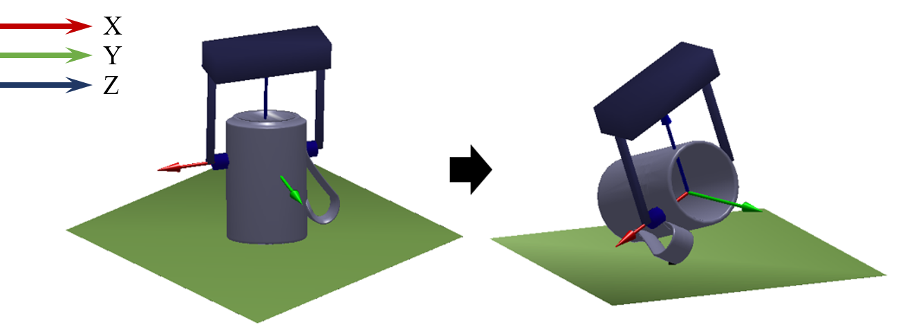
A reorienting problem is defined as follows. Given user-defined initial and final object poses , plan a sequence of gripper motions to move the object from the initial pose to the final pose using the grasps from . An illustration of the problem is shown in Fig. 1.
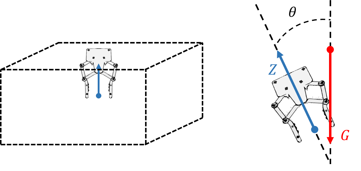
Several constraints need to be considered in the planning problem. First, there should be no collision between the object and any part of the gripper other than the fingertip. Second, the gripper must stay in a preferred workspace so as to avoid singularities as well as collision with the environments. The workspace constraint we use in this paper is defined based on a common picking system, as shown in Fig. 2: the gripper position must stay within a bounding box described by two corner points and , while the gripper tilting angle has an upper limit . Zero tilting angle is the ”palm down” pose, during which the axis of the grasp frame points upward. Other form of workspace constraints can be incorporated into our algorithm as long as they are linear on the gripper pose.
IV Modeling for Reorienting
In this section we introduce the motion primitives for reorienting, and provide thorough mechanical analysis. In the end we provide two theorems about the stability of pivoting and the contact mode between the object and the table, which will be the foundation of the planning method in the next section.
We start with a list of assumptions made in our modeling.
-
1.
The scenario includes one object on a horizontal table, and one robot with a parallel gripper.
-
2.
The object motion is quasi-static, i.e. inertia forces are negligible.
-
3.
In pivoting, the object only rotates about the grasp axis in gripper frame.
-
4.
The friction between the object and the table can be modeled by Coulomb friction and stiction.
We model modeling uncertainties including friction, object COM position, actual grasp locations with bounded error. The workspace constraints make sure the robot will not hit singularity and have no collision with the environment.
IV-A Motion Primitives
We learn two motion primitives from human pinch grasps. The first one is pivot-on-support (Fig. 3. The gripper grasps two antipodal points on the object surface, while allowing the object to rotate passively about the grasp axis. The grasped object also maintains contact(s) with the table under gravity. We make no assumptions on whether the object is sticking or slipping on the table. Given a gripper pose, the possible object poses have one rotational freedom. If we further know the contact location(s) between the object and table, we can determine the unique object pose kinematically.
Note that pivoting can be unstable. The contact between the object and the table could break under gravity for certain configurations. If we continue to rotate the object, it will fall over and break the quasi-static assumption. Looking for a stable rotation trajectory is tricky. Instead, we continue rotating the object when pivoting is unstable, but with a firm grasp instead to avoid falling. This is our second motion primitive roll-on-support in which the gripper grasp the object firmly so that the object motion follows the gripper exactly. We still let the object contact the table, so that we can switch between the two motion primitives easily. To summarize, we let the object rotate directly towards the goal, during which the gripper uses pivot-on-support whenever possible, and switches to roll-on-support otherwise. In the following, we use pivoting and rolling to refer to the two motion primitives.
In Sec. VII, we provide the fingertip design we used to switch between the two motion primitives. The choice of motion primitive, , is a discrete decision variable that the planning algorithm needs to compute.
IV-B Mechanics of Pivot-on-support
Although it’s straightforward to compute a gripper pose from a desired object pose, in order to use pivoting we still need to consider two more things about its mechanics. Firstly we need to know when is pivoting stable/unstable, so that we can choose the right motion primitive to use. Secondly we need to know when the object can slide on the table, during which the robot gripper may translate freely in the horizontal directions. This make it easier for the robot to stay in a confined workspace.
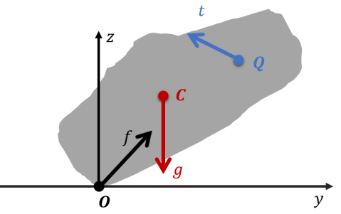
To analyze the stability of 3D pivoting, consider the object motion in the plane perpendicular to grasp axis, as shown in Fig. 4. Call this plane the pivoting plane. Assign a frame to the pivoting plane by setting the origin at the contact point between the object and the table, align the X axis with the grasp frame X axis, align the Y axis with the table. Z axis is determined by the right hand rule. Call this frame the pivoting plane frame.
We do not assume the plane is fixed during pivoting (as we did before in [18]), i.e. the gripper could have any 3D motion. Previous works on mechanics of pivot-on-support restricted the points O, C and Q to be co-linear, and focused on computing the required pushing force [1]. We remove this restriction and perform stability analysis for all possible pivoting scenarios.
For a quasi-static system, at any time the force system must be in equilibrium ():
| (1) |
Inertia force is ignored due to the quasi-static assumption. Eliminate term we have
| (2) |
Denote as the Coulomb friction coefficient between the object and the table. The contact reaction force must stay within the friction cone:
| (3) |
Note here we use the symbol instead of to describe the influence of a tilted pivoting plane. The cone described by is the projection of the actual 3D friction cone onto the pivoting plane. In this work we assume the gripper tilting angle satisfies , otherwise the projection would no longer be a cone.
The pivoting system is stable as long as a solution exists for the force equilibrium (2) and friction constraint (3). Infeasibility means an equilibrium is not possible and the object will topple over. We can discuss the existence of solutions by looking at the - curve along with the friction cone.
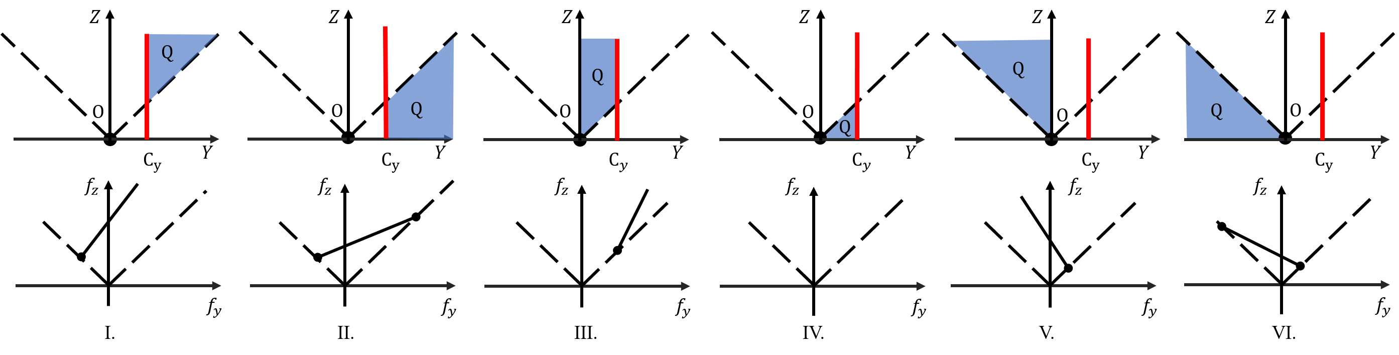
Depending on the locations of and in the pivoting plane, we have six possible situations illustrated by the six columns in Fig. 5. In each column, the top figure shows the positions of and relative to for that situation. The bottom figure shows the corresponding solution set of . In all figures, we also show the friction cones in black dashed line.
When we read Fig. 5, it’s important to remember the gripper moves in 3D space. The contact force during sliding may project to anywhere inside the friction cone in the pivoting plane, which implies that although equation 3 still holds, a strict inequality no longer means the contact can not slide.
The robot actions, i.e. the gripper velocities, do not directly control the force . Instead, the gripper velocity command only determines in what motion the contact tend to move. Then we can use Fig. 5 to tell what will happen.
In scenario I and V, if the contact tend to move towards (roughly means the gripper pulling away from ), from the figure we know the friction will be at most the intersection of the friction cone and the line of . So the contact is sliding. However, if the contact tend to move away from (roughly means the gripper push against the contact ), from the figure we know the friction force exists and never intersects the friction cone, which means the contact may be sticking. If the contact is not moving, the force could be anywhere on the solid line above the friction cone, so the contact may be sticking. If the gripper only moves in the pivoting plane, all the “may be sticking” here becomes strictly sticking.
Similarly in scenario II and VI, if the contact tend to move, the object will slide with limited friction. If the contact does not move, the object may be sticking.
In scenario III, if the contact tend to move towards , there is no solution in equilibrium. If the contact tend to move away from , contact force will either be on the only feasible point on the friction cone, or be infeasible, depending on the exact force from gripper. We ignore this stable solution since it is extremely sensitive to the gripper force and very hard to maintain. Finally if the contact is not moving, a stable, “may be sticking” solution exists if the gripper is pushing towards with enough force. This solution corresponds to the solid line above the friction cone.
In scenario IV, there is no solution in equilibrium no matter how we move the gripper. The analysis above is summarized in table I.
| O moves towards Q | O moves away from Q | O is static | ||||
| I, III | Sliding | Impossible (be stuck) |
|
|||
| II, VI | Sliding | Sliding |
|
|||
| III | Unstable | Unstable |
|
|||
| IV | Unstable | Unstable | Unstable |
In all scenarios except III and IV, a solution exists no matter how the gripper moves. These observations lead to the following sufficient condition for stability:
Theorem 1.
Proof.
The condition corresponds to I, II, V and VI in Fig. 5. As per the analysis above, the force equilibrium constraints have solutions in all these cases. ∎
Condition (4) is not necessary since a solution exists for scenario III. We do NOT use this solution because it is hard to implement. On the one hand the solution requires sticking with certain force, which is hard to implement precisely. Note the condition described in theorem 1 has no requirement on force. On the other hand it is hard to tell whether we are in III or IV since the friction modeling could have large errors. On the contrary, the condition in theorem 1 has nothing to do with the friction coefficient between the object and the table.
We can also come up with a sufficient condition for sliding on the table from Fig. 5:
Theorem 2.
When the stability condition (4) for pivoting is satisfied, the object can slide on the table without sticking
-
•
if the grasp position is outside of the friction cone;
-
•
or if the proposed gripper motion will move the contact towards .
Proof.
The two theorems make it possible to design simple yet effective planning algorithms.
IV-C Simplified Mesh Model
In practise, the location of the contact point is computed as the lowest point on the object mesh model. So the planning algorithm presented in the next section involves manipulating the convex hull of the object mesh model. A delicate model with thousands of facets will slow down the algorithm. We instead work with a simplified (triangle counts reduced) mesh model, and plan robustly against the modeling error.
Denote as the vertices of the mesh model convex hull and the simplified mesh model convex hull, respectively. Denote as the Hausdorff distance between two meshes:
| (5) |
In the following we simplify as . The following theorem determines the range of possible locations of the contact point :
Theorem 3.
Denote as the bottom point on the simplified mesh, i.e.
Then the actual contact point on the original mesh, defined by
must be within the following set:
denotes the ball of radius centered at point .
Proof.
The actual height of the table surface is upper bounded by:
From the definition of Hausdorff distance we know that points on is bounded in balls of radius centered at points on :
As a result, the balls that could possibly touch the table are centered at
∎
Theorem 3 is useful for plan robustly against model simplification error.
V Planning Under Modeling Uncertainties
Now we are ready to design a reorienting planning algorithm that is robust to modeling errors.
Using pivoting, a parallel gripper can reorient an object without releasing the object. However, for some difficult reorienting problems, it may still be necessary for the robot to leave the object on some stable placements, change the grasp location then reorient again several times. This involves planning at different levels, we handle them separately.
V-A Reorienting Planning Given One Grasp Location
We firstly focus on the reorienting problems that can be solved with only one grasp location. Assume the choice of grasp is given. We now need to solve for a trajectory of continuous gripper motion as well as the discrete choices of modes, subjected to pivoting stability constraints, collision-avoidance (between object and gripper) constraints and robot workspace constraints. Discretize the trajectories into time steps, the planning problem takes form of a Mixed-Integer-Programming which suffers from combinatorial explosion of modes. However, we can efficiently find good solutions by decomposing the planning into four steps:
V-A1 Plan for object rotation
In the first step we only compute a trajectory of object rotations. To find the shortest path that connects the initial and final object orientations, we perform a spherical linear interpolation(SLERP) with steps to obtain a evenly-spaced rotation trajectory.
Some workspace constraints are only influenced by the object rotation, e.g. the minimal distance between the fingertips and the table. We check the trajectory for these constraints, and declare infeasibility if a violation happens.
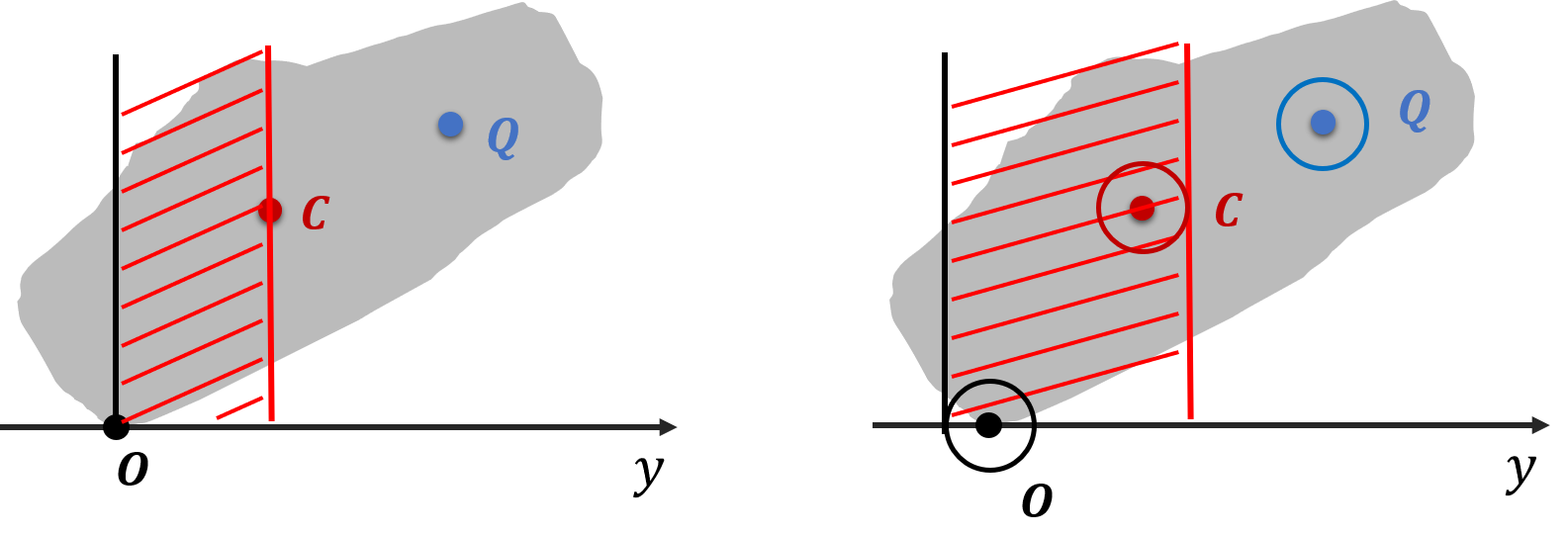
V-A2 Choose motion primitives
We choose pivoting over rolling whenever pivoting is stable. The object orientation determines the relative position of point , and , so we can check the stability of pivoting at each time step using theorem 1, as shown in Figure 6, left. Note that due to mesh simplification the contact point has uncertainty that can be computed from theorem 3. The measurement uncertainty of the center of mass brings uncertainty into . Perception errors in the object initial pose will pass on to . To handle these uncertainties, we declare a pose to be stable for pivoting only if theorem 1 is satisfied under all possible locations of , and , as shown in Figure 6, right. The robust version of condition 4 is:
| (6) |
where
| (7) |
In this way, we also handle multiple contacts naturally. If there are more than one contact points between the object and the table in the pivoting plane, all of these points will be considered in .
Note that if we only choose to do rolling, the method reduces to a pick-and-place reorienting. This is why the solutions of our method is a super set of the pick-and-place solutions.
V-A3 Plan for gripper rotation
With the object rotation trajectory fixed, the orientation of the gripper has one degree of freedom: we need to compute the rotation of the gripper about the grasp axis. Denote as the rotation angle from the axis of the pivoting plane frame to the axis of the grasp frame at time step , i.e. when , the tilting angle of the gripper is at the minimal. We need to compute the trajectory .
The rotation of the gripper has several constraints. First of all, the 3D orientation of the gripper must satisfy the tilting cone limit. The intersection between the pivoting plane and the 3D cone with gripper tilting angle limit as half aperture gives a 2D cone on the pivoting plane, which forms a (symmetric) upper and lower bound on : . The bound may be different at each time step, since the grasp axis is rotating with the object.
The second constraint comes from collision avoidance between the gripper and the object. Any part of the gripper except the fingertips should not contact the object during the robot motion. To efficiently check the collision between the object and the gripper, we compute for each grasp the range of collision-free angle in the object frame during off-line computation. The constraint provides also an upper and a lower bound on at each time step: .
The third constraint comes from the fact that the gripper has to rotate along with the object when it is not pivoting. Denote as a selection matrix with only 1 and 0 on its diagonal, it selects the entries of that correspond to firm grasps. Denote , we can express the vector of for as . Denote as the array of object incremental rotations measured in the pivoting plane, we can express this constraint as a linear equality on :
| (8) |
We can illustrate the gripper rotation planning problem in figure 7, which shows the gripper rotation angle and all kinds of constraints at each time step. Our task is to find a path from time step one to time step , while staying within the tilting angle limit (black dotted lines), avoiding collision region (red shaded areas), and follow object rotation within the rolling zones (blue shaded areas).
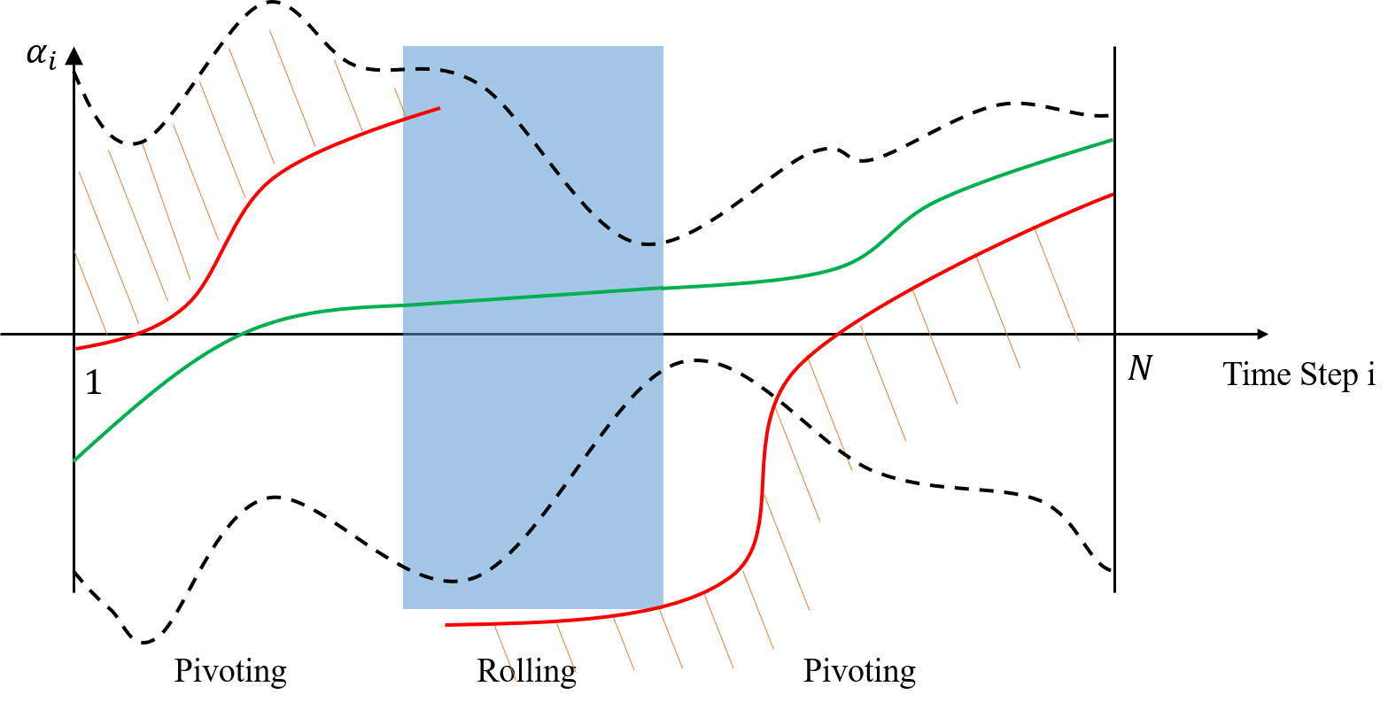
There are usually infinite many solutions that satisfies all the constraints. We find a unique one by applying two preferences: the solution should involve less robot motion; the gripper should stay close to the upright pose . Denote , we can formulate an optimization problem for :
| (9) |
The optimization formulation in (9) is a quadratic programing (QP), which can be solved efficiently. Finally we can compute the gripper orientation for each time step :
| (10) |
where the function computes the quaternion for the rotation of angle about axis . denote the X axis and quaternion of the pivoting plane frame (i.e. the grasp axis) at time step respectively.
V-A4 Plan for gripper translation
Finally we compute the horizontal translations of the gripper, described by the horizontal velocity of the gripper frame . The motion needs to satisfy three constraints. Firstly, the gripper must stay in the workspace bounding box:
| (11) |
Secondly, the motion must ends at the final gripper pose (computed from the desired object pose):
| (12) |
Finally, the feasible direction of the gripper translation is limited. Denote as the change of gripper position in XY with respect to the contact computed from object rotations, we have the relation between and contact velocity :
| (13) |
From theorem 2 we know there are three possible situations for constraints on :
-
1.
(Rolling) The object may not be able to slide.
-
2.
(Pivoting) The object can slide such that moves towards .
-
3.
(Pivoting) The object can slide in all directions.
Denote the set of time step s for each situation as and . For , the gripper motion should make sure the contact does not move in the world frame:
| (14) |
For , we have a half plane constraint on . For the sake of being robust to modeling errors, we shrink the half plane into a cone:
| (15) |
Here is a positive constant for adjusting the shape of the cone, is an unit vector that parallels the axis of the pivoting plane frame and points from towards . is an unit vector in the table plane, and is vertical to . Rewrite this constraint in terms of using equation 13:
| (16) |
For , there are no additional constraints.
Denote as a concatenated vector of all the . We find a unique solution of by minimizing the gripper motion distance:
| (17) |
subject to the constraints (11)(12)(14) and (16). This is again a QP problem which can be solved efficiently.
The complete procedure for solving reorienting given one grasp location is summarized in algorithm 1.
V-B Search for A Sequence of Reorientings
Sometimes we cannot reorient the object to the goal pose using only one grasp location. In such case it is necessary to place the object down on a stable placement and reorient again with a different grasp location, and repeat this process when necessary. We find such multi-step reorienting plans by building and searching on a graph of object stable placements, we call it Stable Placements Graph.
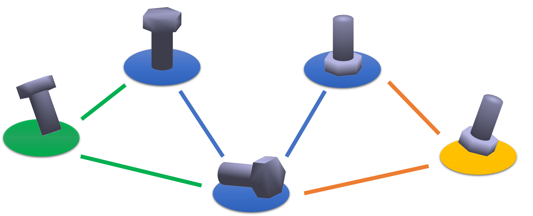
Our graph search idea is built upon Wan’s Regrasp Graph[40], in which a graph connecting different object-gripper poses is computed off-line. The graph was then used for searching pick-and-place based motion plans. With pivoting being available, our stable placements graph improves Wan’s work in two ways:
Firstly, each node on our graph corresponds to a unique object stable placement instead of a specific grasp pose. We no longer need to discretize gripper angles, thus remove the second layer in Wan’s Regrasp Graph. We end up with a much smaller graph. We connect two nodes in the stable placements graph as long as they have common grasp locations, rather than common grasp poses.
Secondly, we add the user specified initial and final object poses to the graph as the starting and ending node during planning time. Since our graph is very small, it takes no time to check the connection between the new nodes and the existed nodes. So this step adds little time to the online computation.
Algorithm 2 summarizes the off-line computation for creating the graph. denotes the mesh simplification described in Section IV-C. and are the same as in [40]: samples anti-podal grasp locations on the object surface; finds stable placements of the object by checking whether the gravity projection is inside of the support polygon for each surface on its convex hull.
The searching algorithm for multi-step reorienting plans is shown in Algorithm 3. Function denotes our planning method for one grasp location (Section V-A).
We use Dijkstra to find the shortest path on the graph, minimizing the number of grasp changes. For each edge on the path, if the destination node is not the goal node, we can choose and freely for that node. To encourage efficient solutions and stay within workspace constraint, we set to be the center of the workspace bounding box, pick as the closest orientation for that stable placement. Then we run algorithm 1 for each available grasps and pick the one with shortest gripper motion. If none of the grasps has a solution, we remove this edge from the stable placements graph and run graph search again.
VI HARDWARE IMPLEMENTATION
VI-A Gripper Design
The analysis above has the following assumptions on the gripper hardware:
-
•
The gripper can switch between firm grasp and pivoting;
-
•
In pivoting, the object only rotates about the grasp axis without tangential slipping.
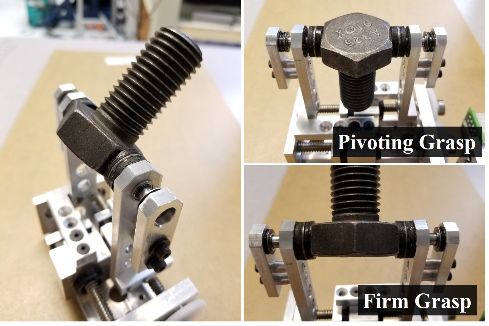
These requirements can be met by installing customized fingers on off-the-shelf parallel grippers or pinch grippers, making a “two-phase gripper” ([10, 36]). We propose a simple finger design for two-phase grippers, as shown in figure 9. Each of the finger has a rotational shaft installed on a ball bearing parallel to the grasp axis. The shaft has two degrees of freedom: rotation about the axis, and translation along the axis. A round, thin piece of high friction rubber is installed on the shaft as the fingertip, which moves along with the shaft. The other side of the fingertip is also stuffed with rubber. This side could touch the rough surface (filing paper) on the finger and create a high friction contact. When the finger is open, the shaft is pushed away from the rough surface from the other end by a spring-levering mechanism.
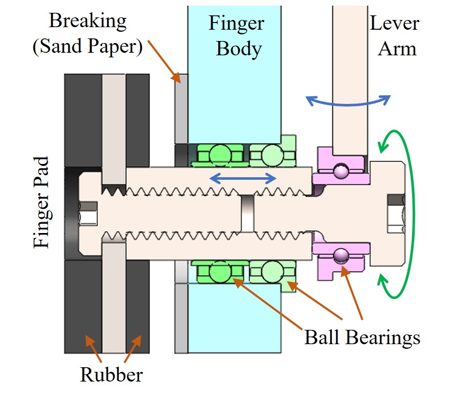
The structures described above form a rotation mechanism and a braking system. When the finger grasps an object, the object can rotate with the shaft freely. The rotational friction is low due to the ball bearing. If the gripper continues to close the finger, the shaft will be pushed off until the back of the fingertips touches the rough surface, at which point the rotation is braked down.
Similar to existed two-phase gripper designs ([10, 36]), our gripper achieve grasp mode switching by changing grasp force without another motor. The spring maps grasp force to grasp width. A simple control strategy is to first grasp firmly and record the grasp width, then the gripper can switch to pivoting by open the finger by half of the shaft travel.
Our design is unique in that it maintains the same contact patches on the object during each grasp mode and the switching between modes. The contact is always sticking. Without change of contact patches or contact modes, we eliminate a source of uncertainty.
One important characteristic of two-phase grippers is the range of gripping force for the rotation mode. The force has a lower bound to avoid tangential slip; and a upper bound for switching to firm grasp mode. The range should not be too small, otherwise the actual gripper mode will be sensitive to noises in gripper force. In our design, we make low by choosing high friction material for the fingertips, make high by choosing springs with high stiffness.
To reorient an object, it is important that the gripper can approach many different grasp locations. To approach the grasp locations that are close to the table, the overall finger width in the grasp axis direction must be as small as possible. Comparing with our previous design [18], we reduce the fingertip width by adopting a lever system for the spring, instead of placing the spring directly on the grasp axis.
VI-B Execute Reorienting with Hybrid Force-velocity Control
During roll-on-support, the object pose is over-constrained by the table and the gripper. During pivot-on-support, the object pose is also over-constrained if the contact on the table is sticking. To avoid crushing the object, we can not control the velocity of all six joints of the robot simultaneously.
Instead, we adopt hybrid force-velocity control to execute the two motion primitives. During rolling, the gripper performs force control in the Z direction with a certain force to maintain the contact between the table, while all the other five DOFs (3D orientation and XY translation) are executed exactly by velocity control. Together with one constraint on the Z direction from the table contact (there is no XY constraint since the normal force is limited by force control), the object pose is determined without conflicts.
During pivoting, the situation is more complicated. If the table contact is sliding, the gripper should only perform velocity control. In this way the gripper imposes five constraints on the object, together with the table Z constraint they uniquely determine the object pose. If the table contact is sticking, we do force control in Z direction instead.
Our hybrid force-velocity control is implemented on a position-controlled industrial robot arm with wrist mounted force-torque sensor [25].
VII Evaluation
VII-A Simulation and Comparison with Pick-and-place
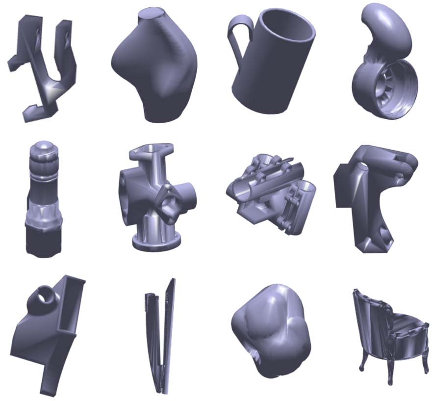
We simulate reorienting tasks on 12 objects with non-trivial shapes (over 2000 facets per object on average) obtained from Dex-Net [24], as shown in figure 10. In off-line computation, we sample at most 50 grasp positions for each object. After trimming similar grasps, we keep 10 to 40 grasps for planning.
The workspace bounding box is a rectangle region. We scale each object to fit into an cube. For each object, we create 100 reorienting problems by sampling 100 pairs of initial and final object poses with feasible grasp locations.
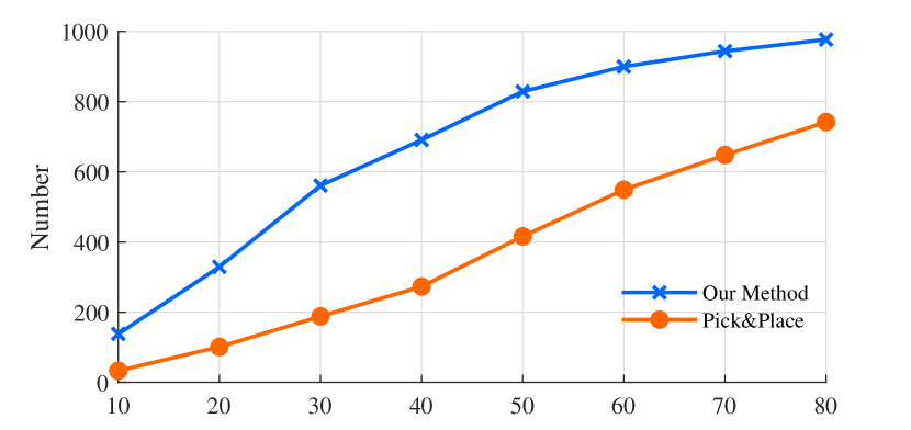
To evaluate the algorithm performance under different workspace constraints, we run the 1200 sample problems multiple times, with tilting angle limit ranging from 10 to 80 degrees. For comparison, we also implement a pick-and-place based method by always avoiding pivoting in algorithm 1. The performance of our method and pick-and-place are shown in figure 11. Notice that our method can solve more problems under all conditions (Figure 11(a).
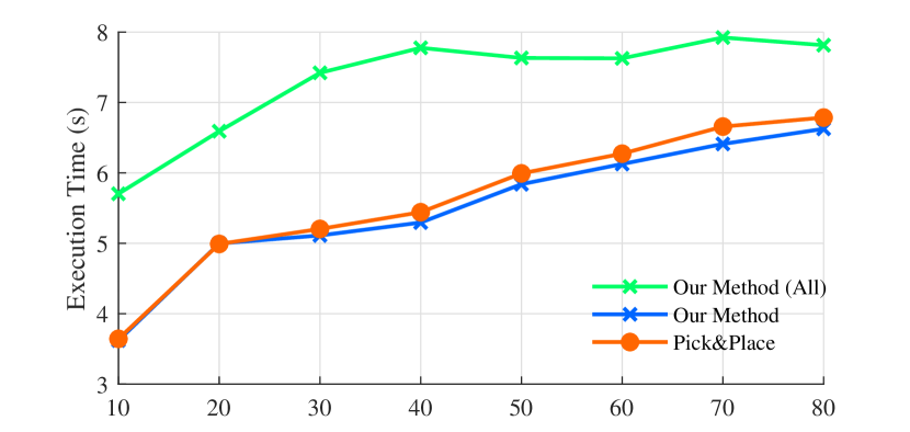
Figure 11(b) shows the average execution time of the solved motion plans generated by both methods. The robot end-effector maximum velocity is limited by for translation and for rotation, under which our motion plan takes around seven seconds to execute (the green line). Notice that results of our method include solutions for more challenging problems. To make a fair comparison, we also show the average execution time for the problems that can be solved by both methods, shown by the orange line and the blue line, respectively. Our method is slightly more efficient comparing with pick-and-place.
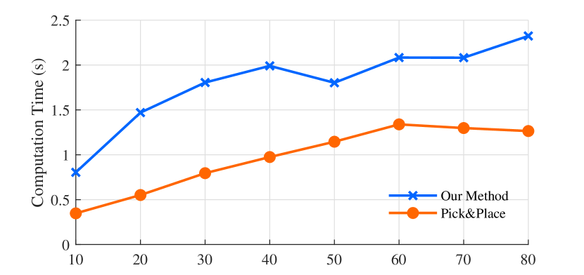
Figure 11(c) shows the average computation time taken by each method to solve a reorienting problem. We haven’t optimize the code for speed; the data are measured on a desktop with Intel Xeon 3.10GHz CPU running single-thread Matlab. The average computation times for solving one problem (or declare failure) are and for our method and pick-and-place, respectively. The off-line computation described in algorithm 2 takes several minutes per object, depending on the complexity of the object mesh.
VII-B Experiments
We test our method with an ABB IRB120 industrial robot and the two-phase gripper described in VI. To implement multi-step motion plans, we obtain object 3D pose feedback from vision before each grasp. The vision system includes two Intel RealSense D415 RGBD cameras. There is no vision feedback when the fingers are on the object.
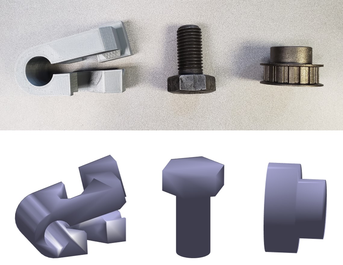
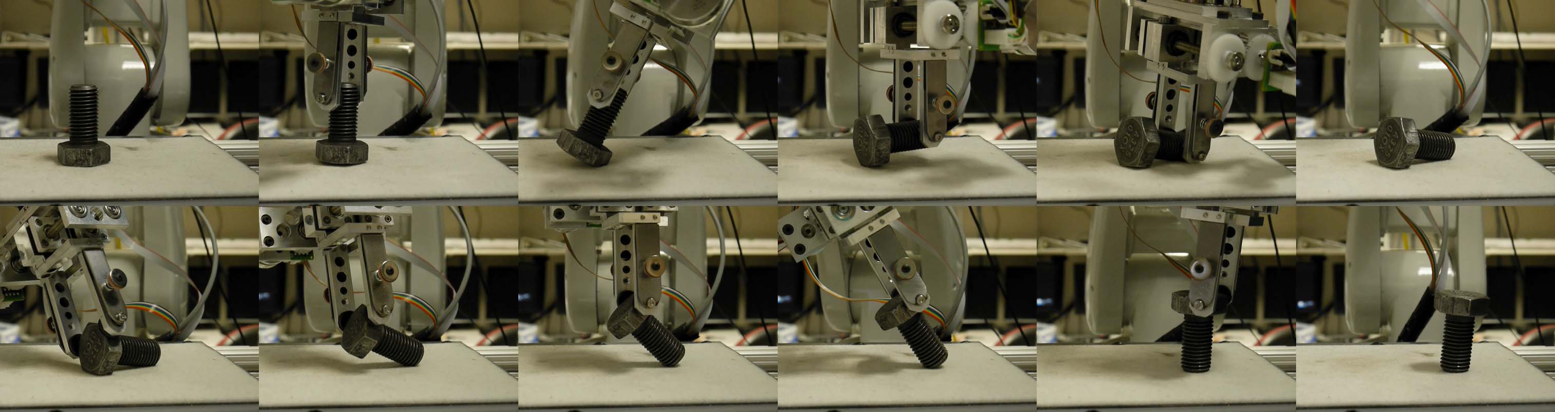
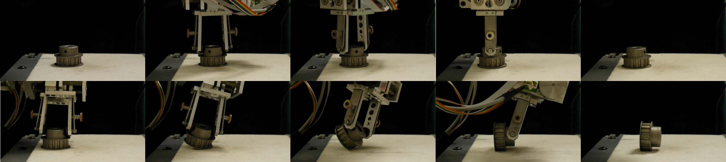
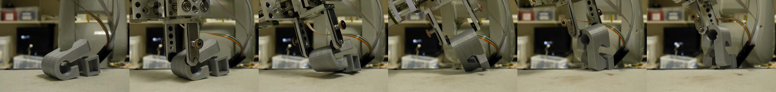
Figure 12 shows the objects we used in experiments, including a metal screw, a metal pulley wheel and a 3D printed clamp from DexNet dataset. For the two real objects, we use rough models for perception and planning. Solutions of one example problem for each object are shown in figure 13,14 and 15. More experiments can be found in the supplementary video.
VII-C Failures and future work
The experiment can fail in several ways. The most common type of failure is unexpected slipping at the grasp location, which is assumed not to happen in planning. The problem can be fixed by increasing the maximum resistance force at the finger (use stronger gripper, higher frictional fingertips), or considering tangential force limit constraint in planning. It’s also helpful to implement better force control, since the large tangential force is often caused by the variations in force tracking.
The other main reason for failure is wrong estimation of the friction coefficient between the object and the table. When our estimation is off too much, theorem 1 fails to predict the stability of pivoting. After we tune and obtain a more accurate friction coefficient, this problem no longer happens. In the future, an online estimation algorithm for updating friction parameter and closed-loop control may solve this issue.
Acknowledgment
The authors would like to thank Nikil Chavan-Dafle, François Hogan, Mohamed Raessa and Weiwei Wan for helpful discussions.
References
- [1] Y. Aiyama, M. Inaba, and H. Inoue. Pivoting: A new method of graspless manipulation of object by robot fingers. In Proceedings of the 1993 IEEE/RSJ International Conference on Intelligent Robots and Systems, volume 1, pages 136–143 vol.1.
- [2] A Patricia Ambler, Harry G Barrow, Christopher M Brown, RH Burstall, and Robin J Popplestone. A versatile computer-controlled assembly system. In Proceedings of the 3rd international joint conference on Artificial intelligence, pages 298–307. Morgan Kaufmann Publishers Inc., 1973.
- [3] David L Brock. Enhancing the dexterity of a robot hand using controlled slip. In 1988 IEEE International Conference on Robotics and Automation, pages 249–251, 1988.
- [4] Chao Cao, Weiwei Wan, Jia Pan, and Kensuke Harada. Analyzing the utility of a support pin in sequential robotic manipulation. In Robotics and Automation (ICRA), 2016 IEEE International Conference on, pages 5499–5504. IEEE, 2016.
- [5] Chao Cao, Weiwei Wan, Jia Pan, and Kensuke Harada. An empirical comparison among the effect of different supports in sequential robotic manipulation. In Intelligent Robots and Systems (IROS), 2016 IEEE/RSJ International Conference on, pages 2548–2553. IEEE, 2016.
- [6] Brian Carlisle, Ken Goldberg, Anil Rao, and Jeff Wiegley. A pivoting gripper for feeding industrial parts. In ICRA, pages 1650–1655, 1994.
- [7] N. Chavan-Dafle and A. Rodriguez. Prehensile pushing: In-hand manipulation with push-primitives. In 2015 IEEE/RSJ International Conference on Intelligent Robots and Systems, pages 6215–6222.
- [8] Nikhil Chavan-Dafle, Rachel Holladay, and Alberto Rodriguez. In-hand manipulation via motion cones. In Robotics: Science and Systems (RSS), 2018.
- [9] Nikhil Chavan-Dafle, Kyubin Lee, and Alberto Rodriguez. Pneumatic shape-shifting fingers to reorient and grasp. arXiv preprint arXiv:1809.08420, 2018.
- [10] Nikhil Chavan-Dafle, Matthew T Mason, Harald Staab, Gregory Rossano, and Alberto Rodriguez. A two-phase gripper to reorient and grasp. In Automation Science and Engineering (CASE), 2015 IEEE International Conference on, pages 1249–1255. IEEE, 2015.
- [11] Nikhil Chavan-Dafle and Alberto Rodriguez. Sampling-based planning of in-hand manipulation with external pushes. arXiv preprint arXiv:1707.00318, 2017.
- [12] Kyoungrae Cho, Munsang Kim, and Jae-Bok Song. Complete and rapid regrasp planning with look-up table. Journal of Intelligent & Robotic Systems, 36(4):371–387, 2003.
- [13] Silvia Cruciani, Yin Hang, and Danica Kragic. In-hand manipulation of objects with unknown shapes. 2019.
- [14] N. C. Dafle, A. Rodriguez, R. Paolini, B. Tang, S. S. Srinivasa, M. Erdmann, M. T. Mason, I. Lundberg, H. Staab, and T. Fuhlbrigge. Extrinsic dexterity: In-hand manipulation with external forces. In 2014 IEEE International Conference on Robotics and Automation (ICRA), pages 1578–1585, 2014.
- [15] Anne Holladay, Robert Paolini, and Matthew T Mason. A general framework for open-loop pivoting. In 2015 IEEE International Conference on Robotics and Automation (ICRA), pages 3675–3681.
- [16] Yifan Hou, Zhenzhong Jia, Aaron M Johnson, and Matthew T Mason. Robust planar dynamic pivoting by regulating inertial and grip forces. In The 12th International Workshop on the Algorithmic Foundations of Robotics (WAFR). Springer, 2016.
- [17] Yifan Hou, Zhenzhong Jia, and Matthew T Mason. Fast planning for 3d any-pose-reorienting using pivoting. In 2018 IEEE International Conference on Robotics and Automation (ICRA), pages 1631–1638. IEEE, 2018.
- [18] Yifan Hou, Zhenzhong Jia, and Matthew T Mason. Fast planning for 3d any-pose-reorienting using pivoting. In International Conference on Robotics and Automation (ICRA) 2018. IEEE Robotics and Automation Society (RAS), May 2018.
- [19] Alan D Kalvin and Russell H Taylor. Superfaces: Polygonal mesh simplification with bounded error. IEEE Computer Graphics and Applications, 16(3):64–77, 1996.
- [20] Reinhard Klein, Gunther Liebich, and Wolfgang Straßer. Mesh reduction with error control. In Proceedings of the 7th conference on Visualization’96, pages 311–318. IEEE Computer Society Press, 1996.
- [21] Sergey Levine, Chelsea Finn, Trevor Darrell, and Pieter Abbeel. End-to-end training of deep visuomotor policies. The Journal of Machine Learning Research, 17(1):1334–1373, 2016.
- [22] Tomas Lozano-Perez, J Jones, Emmanuel Mazer, P O’Donnell, W Grimson, Pierre Tournassoud, and Alain Lanusse. Handey: A robot system that recognizes, plans, and manipulates. In Robotics and Automation. Proceedings. 1987 IEEE International Conference on, volume 4, pages 843–849. IEEE, 1987.
- [23] Tomás Lozano-Pérez and Leslie Pack Kaelbling. A constraint-based method for solving sequential manipulation planning problems. In Intelligent Robots and Systems (IROS 2014), 2014 IEEE/RSJ International Conference on, pages 3684–3691. IEEE, 2014.
- [24] Jeffrey Mahler, Jacky Liang, Sherdil Niyaz, Michael Laskey, Richard Doan, Xinyu Liu, Juan Aparicio Ojea, and Ken Goldberg. Dex-net 2.0: Deep learning to plan robust grasps with synthetic point clouds and analytic grasp metrics. arXiv preprint arXiv:1703.09312, 2017.
- [25] J. Maples and J. Becker. Experiments in force control of robotic manipulators. In Proceedings. 1986 IEEE International Conference on Robotics and Automation, volume 3, pages 695–702, Apr 1986.
- [26] Igor Mordatch, Zoran Popović, and Emanuel Todorov. Contact-invariant optimization for hand manipulation. In Proceedings of the ACM SIGGRAPH/Eurographics symposium on computer animation, pages 137–144. Eurographics Association, 2012.
- [27] Igor Mordatch, Emanuel Todorov, and Zoran Popović. Discovery of complex behaviors through contact-invariant optimization. ACM Transactions on Graphics (TOG), 31(4):43, 2012.
- [28] Richard Paul, Karl Pingle, Jerome Feldman, and Alan Kay. Instant insanity video from stanford artificial intelligence laboratory (sail).
- [29] Lerrel Pinto and Abhinav Gupta. Supersizing self-supervision: Learning to grasp from 50k tries and 700 robot hours. In Robotics and Automation (ICRA), 2016 IEEE International Conference on, pages 3406–3413. IEEE, 2016.
- [30] Michael Posa, Cecilia Cantu, and Russ Tedrake. A direct method for trajectory optimization of rigid bodies through contact. The International Journal of Robotics Research, 33(1):69–81, 2014.
- [31] Anil Rao, David J Kriegman, and Kenneth Y Goldberg. Complete algorithms for feeding polyhedral parts using pivot grasps. IEEE Transactions on Robotics and Automation, 12(2):331–342, 1996.
- [32] Jean-Philippe Saut, Mokhtar Gharbi, Juan Cortés, Daniel Sidobre, and Thierry Siméon. Planning pick-and-place tasks with two-hand regrasping. In Intelligent Robots and Systems (IROS), 2010 IEEE/RSJ International Conference on, pages 4528–4533. IEEE, 2010.
- [33] Jian Shi, J Zachary Woodruff, and Kevin M Lynch. Dynamic in-hand sliding manipulation. In 2015 IEEE/RSJ International Conference on Intelligent Robots and Systems, pages 870–877, 2015.
- [34] Avishai Sintov, Or Tslil, and Amir Shapiro. Robotic Swing-Up regrasping manipulation based on the Impulse–Momentum approach and cLQR control. Ieee T Robot, 32(5):1079–1090, 2016.
- [35] Sascha A Stoeter, Stephan Voss, Nikolaos P Papanikolopoulos, and Heiko Mosemann. Planning of regrasp operations. In Robotics and Automation, 1999. Proceedings. 1999 IEEE International Conference on, volume 1, pages 245–250. IEEE, 1999.
- [36] Hajime Terasaki and Tsutomu Hasegawa. Motion planning of intelligent manipulation by a parallel two-fingered gripper equipped with a simple rotating mechanism. IEEE Transactions on Robotics and Automation, 14(2):207–219, 1998.
- [37] Pierre Tournassoud, Tomás Lozano-Pérez, and Emmanuel Mazer. Regrasping. In Robotics and Automation. Proceedings. 1987 IEEE International Conference on, volume 4, pages 1924–1928. IEEE, 1987.
- [38] Marc Toussaint, Kelsey Allen, Kevin A Smith, and Joshua B Tenenbaum. Differentiable physics and stable modes for tool-use and manipulation planning. In Robotics: Science and Systems, 2018.
- [39] Francisco E Vi, Yiannis Karayiannidis, Christian Smith, Danica Kragic, et al. Adaptive control for pivoting with visual and tactile feedback. In 2016 IEEE International Conference on Robotics and Automation (ICRA), pages 399–406.
- [40] Weiwei Wan, Matthew T Mason, Rui Fukui, and Yasuo Kuniyoshi. Improving regrasp algorithms to analyze the utility of work surfaces in a workcell. In Robotics and Automation (ICRA), 2015 IEEE International Conference on, pages 4326–4333. IEEE, 2015.
- [41] Dustin J Webb and Jur Van Den Berg. Kinodynamic rrt*: Asymptotically optimal motion planning for robots with linear dynamics. In 2013 IEEE International Conference on Robotics and Automation, pages 5054–5061. IEEE, 2013.
- [42] Zhixing Xue, J Marius Zoellner, and Ruediger Dillmann. Planning regrasp operations for a multifingered robotic hand. In Automation Science and Engineering, 2008. CASE 2008. IEEE International Conference on, pages 778–783. IEEE, 2008.
- [43] Eiichi Yoshida, Mathieu Poirier, Jean-Paul Laumond, Oussama Kanoun, Florent Lamiraux, Rachid Alami, and Kazuhito Yokoi. Pivoting based manipulation by a humanoid robot. Autonomous Robots, 28(1):77–88, 2010.