Modeling, simulation and validation of supersonic parachute inflation dynamics during Mars landing
Abstract
A high fidelity multi-physics Eulerian computational framework is presented for the simulation of supersonic parachute inflation during Mars landing. Unlike previous investigations in this area, the framework takes into account an initial folding pattern of the parachute, the flow compressibility effect on the fabric material porosity, and the interactions between supersonic fluid flows and the suspension lines. Several adaptive mesh refinement (AMR)-enabled, large edge simulation (LES)-based, simulations of a full-size disk-gap-band (DGB) parachute inflating in the low-density, low-pressure, carbon dioxide (CO2) Martian atmosphere are reported. The comparison of the drag histories and the first peak forces between the simulation results and experimental data collected during the NASA Curiosity Rover’s Mars atmospheric entry shows reasonable agreements. Furthermore, a rudimentary material failure analysis is performed to provide an estimate of the safety factor for the parachute decelerator system. The proposed framework demonstrates the potential of using Computational Fluid Dynamics (CFD) and Fluid-Structure Interaction (FSI)-based simulation tools for future supersonic parachute design.
Nomenclature
| = | parachute system length parameter |
| = | parachute system diameter parameter |
| = | computational domain |
| = | boundary of the computational domain |
| = | fluid mesh primal cell |
| = | fluid mesh dual cell or control volume |
| = | fluid mesh dual cell boundary |
| = | area weighted dual cell facet normal |
| = | number of nodes attached to the primal cell |
| = | shape function associated with node |
| = | fluid inviscid flux tensor |
| = | approximate Riemann flux |
| = | fluid viscous flux tensor |
| = | fluid conservative variable |
| = | fluid primitive variable |
| = | fluid velocity |
| = | fluid velocity component |
| = | fluid density |
| = | pressure |
| = | total energy per unit volume |
| = | specific internal energy |
| = | temperature |
| = | viscous stress tensor |
| = | heat flux vector |
| = | viscosity |
| = | Mach number |
| = | gas constant |
| = | specific heat ratio |
| = | thermal conductivity |
| = | specific heat at constant pressure |
| = | Prandtl number |
| = | identity matrix |
| = | structure density |
| = | mass matrix |
| = | Young’s modulus |
| = | Poisson’s ratio |
| = | fabric thickness |
| = | structure displacement |
| = | structure displacement component |
| = | structure rotation vector |
| = | structure angular velocity |
| = | rotation matrix |
| = | force vector |
| = | moment vector |
| = | body force |
| = | Green strain tensor |
| = | deformation gradient tensor |
| = | determinant of the deformation gradient tensor |
| = | second Piola-Kirchhoff stress tensor |
| = | fluid-structure interface |
| = | normal of the fluid-structure interface |
| = | void fraction or porosity |
| = | Eulerian coordinates |
| = | distance vector |
| = | material coordinates |
| = | slave node |
| = | master point |
| = | number of slave nodes paired with the master point |
| = | time |
| Subscripts | |
| = | far-field related quantities |
| = | discretized state |
| Superscripts | |
| = | structure related quantities |
| = | fluid related quantities |
| Operators | |
| = | transpose operator |
| = | time derivative |
| = | gradient operator |
1 Introduction
Parachute decelerator systems have been used to successfully land large mass spacecraft on the surface of Mars since the 1970s [1, 2, 3, 4, 5]. However, the dynamics of parachute inflation at supersonic speeds involves complex interdependent phenomena such as interactions between shocks, turbulent wakes and flexible membrane deformations, the ramifications of which still remain unclear. These complex systems have been studied experimentally (mostly in the 1960s) by the US Air Force and subsequently by NASA during the qualification of the Viking program. It has been reported that the flow conditions prevalent in the supersonic flow regime have a profound effect on the performance of a parachute. In particular a high-frequency, large-amplitude oscillation know as breathing was observed for Mach numbers between 1.6 and 4.65 [6, 7]. Furthermore, a parachute may suffer from a rapid fall-off of drag performance at supersonic speeds [8, 9], despite performing well in subsonic air-streams. Cause for even greater concern are the the numerous canopy failures observed in flight tests conducted over the past few decades, which typically occurred during inflation [10, 11], and the limited number of tests that can be performed for developing a better understanding of how to avoid such failures. Despite this, most if not all relevant computational efforts have focused on developing CFD and FSI parachute models for the post-inflation regime [12, 13, 14, 15], which is substantially easier to simulate; few predictive high fidelity simulations of the dynamics of a parachute during its inflation have been reported [16, 17]. Consequently, the Jet Propulsion Laboratory, California Institute of Technology, and Stanford University have initiated a multiyear research collaboration with the goal of advancing the state-of-the-art for modeling the supersonic parachute inflation process. This paper presents results from a numerical study that aims to understand the underlying physics and emphasizes the validation with Mars landing supersonic parachute data.
The parachute inflation process for typical NASA Mars landed missions starts with a mortar fire [18], during which the parachute pack is ejected by the mortar deployment system at a specific ejection velocity to enable successful bag strip and suspension line stretch without line tangling or damage to the parachute during deployment. After suspension line stretch, the parachute inflates rapidly to an initial peak force, followed by one or more partial collapse cycles [18]. Simulation of the first part of this process from the mortar fire until suspension line stretch presents numerous challenges and is beyond the scope of the present study. Consequently, the simulation in the present work focuses on the second part of inflation process commencing at the line stretch stage, with an initial flow condition characterized by turbulence and shock waves carefully established to mitigate any artificial effects. The influence of parachute folding – which is generally ignored in the literature – on the inflation process and initial stress of the parachute fabric was reported in [17] to be significant. Hence, an idealized analytical representation of the line stretch configuration based on a partial unfolding with associated prestress is used for the structure initial state of the parachute in this work.
During inflation, the parachute interacts with supersonic flows and undergoes large deformation and possibly even topological changes. This makes arbitrary Eulerian Lagrangian (ALE) methods [19, 20] unfeasible, even with remeshing techniques [21]. Hence, the Eulerian computational framework with an immersed (embedded) boundary method [22, 23] is adopted in the present study. Specifically, the Finite Volume method with Exact two-phase or two-material Riemann problems (FIVER) [24, 25, 26, 27] is utilized. This method has previously been successfully employed for the simulation of the failure analysis of submerged structures subjected to explosions and implosions [28, 29]. It incorporates in the framework a parallel adaptive mesh refinement based on newest vertex bisection [30, 31, 32], which enables the capturing of various interactions between the fluid subsystem, the nonlinear parachute subsystem, and the forebody. It also enables resolution of all relevant self-contact [33] effects of the parachute during its inflation. This paper overviews several novel techniques recently developed specifically for parachute inflation simulations in this computational framework. They include a homogenized porous wall model that takes into account the flow compressibility, and a suspension line treatment that allows for the interactions of the sub-grid scale suspension lines with the flow. These ingredients have been reported to play a major role in parachute drag performance and overall stability, based on wind-tunnel testing [34, 15, 35], but have been generally neglected or oversimplified by empirical models from the literature [36, 16, 37, 21].
The validation of the framework is presented by comparing simulation results with data collected by the NASA Curiosity Rover during its Mars atmospheric entry [18]. Namely, a full-scale parachute inflated in the low-density, low-pressure Mars atmosphere is simulated by utilizing Adaptive Mesh Refinement (AMR) and Large-Eddy Simulation (LES) of compressible flow, coupled with a highly flexible structure. The canopy breathing, bow shocks and turbulent wake interactions are observed. Comparisons of the drag history and the first peak force with the collected data are presented; reasonable agreements are achieved, even though the forebody is assumed to be rigid without vibrations/oscillations, and the trim angle is set to zero. To the best of our knowledge, this is the first FSI simulation that reasonably matches the Mars landing data.
The aim of the present study is two-fold. First, to overview the techniques developed for parachute inflation simulations. Second, to demonstrate the ability of state-of-art CFD and FSI techniques to accurately predict the first peak and the maximum von Mises stress of supersonic parachute inflation at a manageable computational cost. The remainder of this paper is organized as follows. Section 2 introduces the setup of the simulation including the choice of the suitable initial conditions. Section 3 briefly outlines the mathematical formulation and computational models underlying the adopted dynamic fluid and structural models and their interactions. Section 4 compares critically the results from simulations with in-flight measurements. Finally, conclusions are offered in section 5.
2 Problem setup
The parachute decelerator system considered in the present study is shown in fig. 1. It is that which successfully landed the Curiosity Rover on the surface of Mars in 2012. The system consists of three main components:
-
1.
the DGB parachute canopy comprising a disk part and a band part separated by gap for stability purposes, each primarily made of nylon fabric,
-
2.
the suspension lines, which are made of Technora cord (also referred to in the paper as the cords), and
-
3.
the Mars Science Laboratory (MSL)-like entry vehicle.
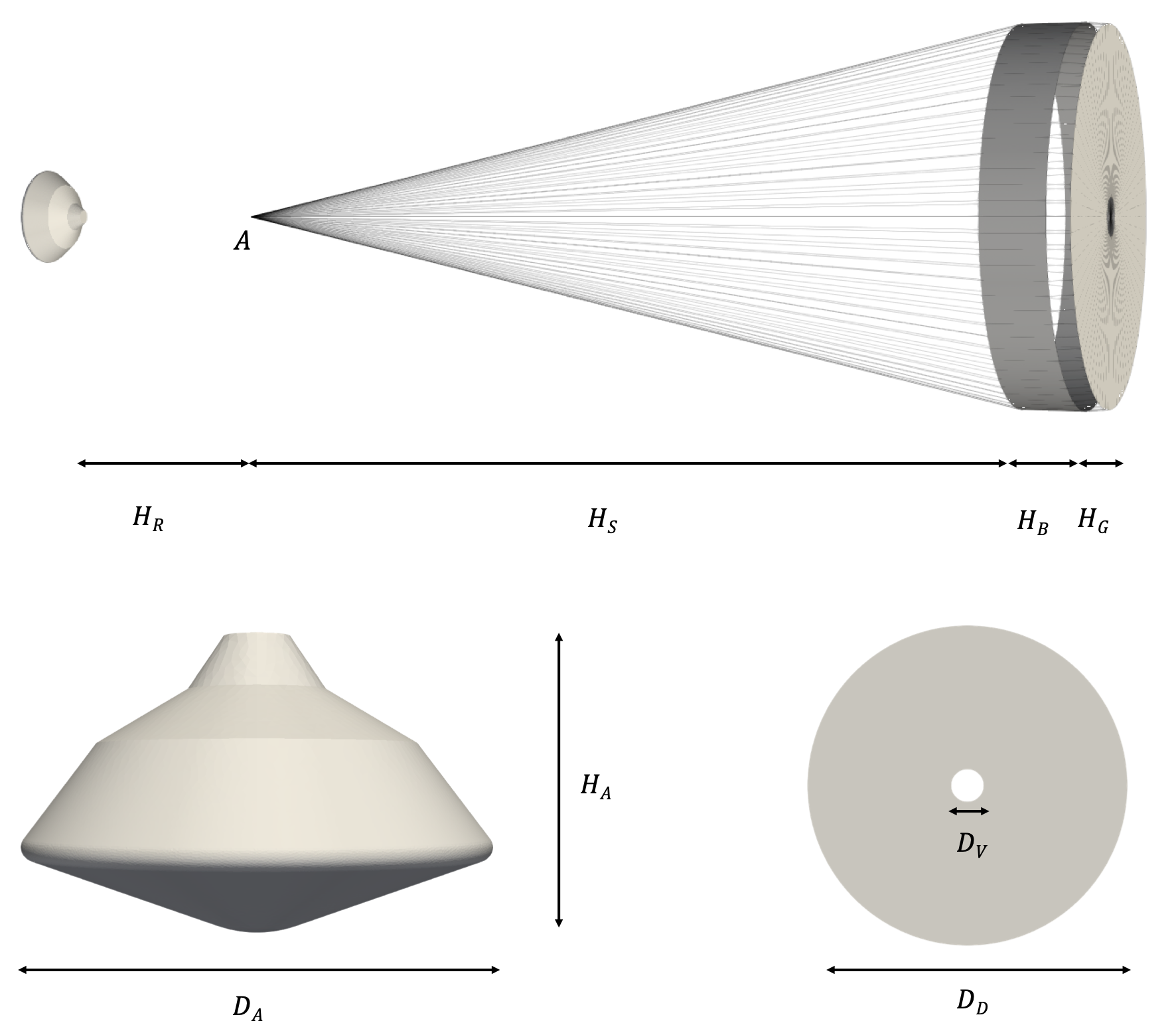
Each of the 40 cords form a continuous loop starting from the confluence point , then passing through the band, disk (via the central vent) and band once again (on the opposite side), before finally terminating back at . This arrangement therefore essentially corresponds to a configuration with 80 suspension lines. The cables are sewed to the fabric of the canopy along the regions in which they align. Additionally, four cables are integrated as radial load carrying members in the band and disk leading and trailing edges. The DGB parachute canopy consists of 80 gores, with each gore comprising an approximately triangular segment in the disk and a rectangular segment in the band. Detailed geometric parameters 111The dimensions of the MSL-like entry vehicle are assumed to be similar to those published in [38]. [18, 38] and material properties [39] are listed in table 2.
| Parameter | Description | Value |
|---|---|---|
| Riser length (including triple bridle) | 8.895 m | |
| Suspension line height | 35.826 m | |
| Band height | 2.580 m | |
| Gap height | 0.904 m | |
| Entry vehicle height | 2.7647m | |
| Entry vehicle diameter | 4.5 m | |
| Vent diameter | 1.576 m | |
| Disk (band) diameter | 15.447m | |
| Suspension line diameter | 3.175 10-3 m | |
| Fabric Young’s modulus | 9.448108 Pa | |
| Fabric Poisson’s ratio | 0.4 | |
| Fabric thickness | 7.6073 10-5 m | |
| Fabric density | 1154.25 kg m-3 | |
| Suspension line Young’s modulus | 2.9511010 Pa | |
| Suspension line Poisson’s ratio | 0.4 | |
| Suspension line density | 1154.25 kg m-3 |
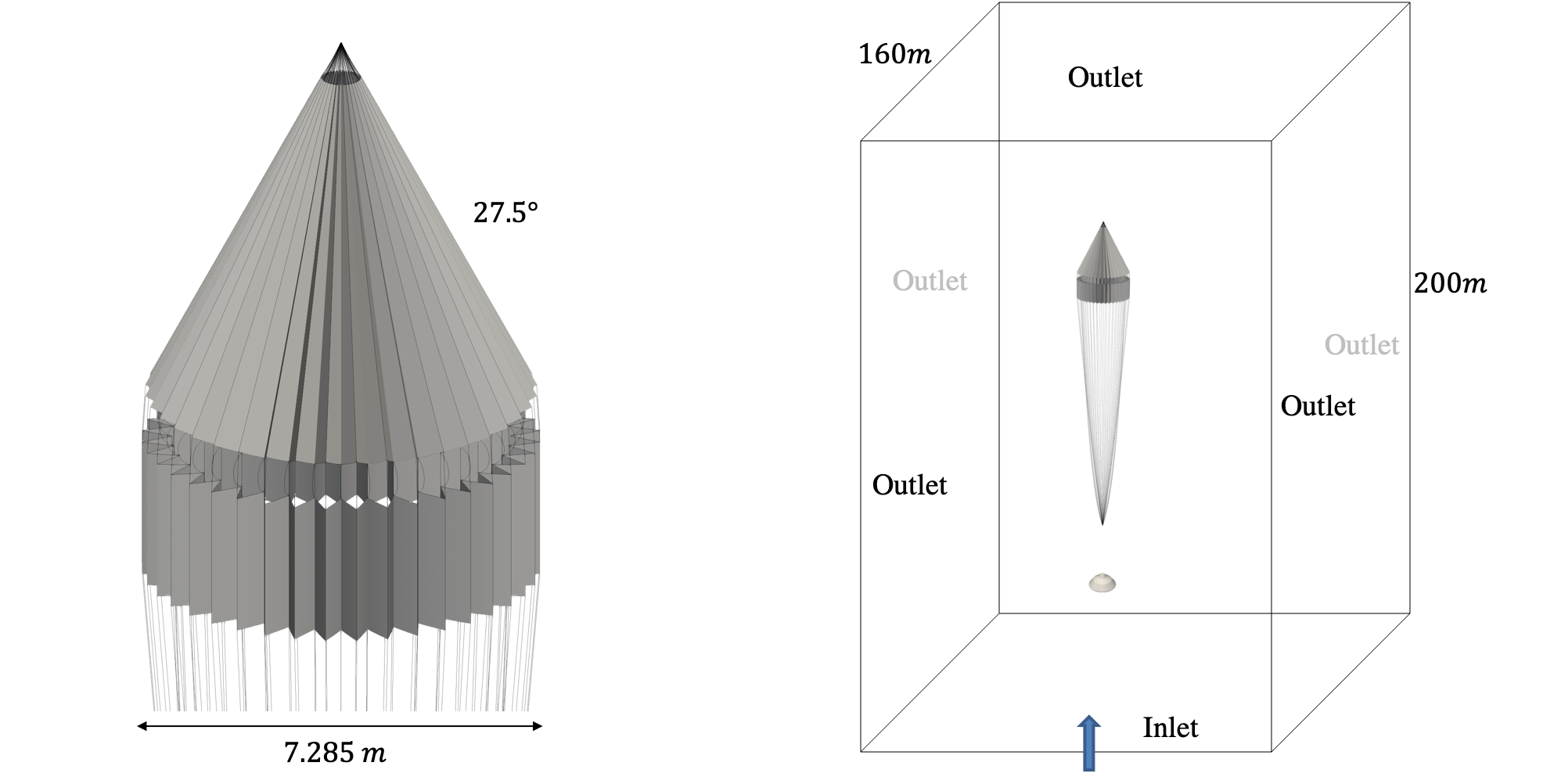
When the spacecraft reaches the Martian atmosphere, it decelerates due to the drag of the entry vehicle, until the velocity reaches below Mach 2. Then, the parachute pack is ejected by a mortar deployment system at a specific ejection velocity. Simulation of the initial deployment and unpacking of the parachute pack commencing from the mortar fire stage presents numerous challenges that are beyond the scope of the present work. Instead, the simulation in the present work is started from the line stretch stage, with an initial flow condition characterized by turbulence and shock waves carefully established to mitigate any artificial effects, and an idealized analytical representation of the line stretch configuration for the parachute canopy (see fig. 2) constructed by rigidly rotating each gore from the as-built configuration which is assumed to be stress-free. The folding angles are and for inner and outer folds of the disk (from the center line to the folds), respectively, resulting in a projected diameter of m. The suspension lines may be specified as either straight lines or as catenary curves to ensure full length. The corresponding pre-stress due to the folding is also taken into account.
To obtain the initial flow conditions, a sequence of fluid simulations were undertaken. First, a quasi steady-state solution was computed for the flow past the fixed entry vehicle by simulating the evolution of the flow starting from a uniform initial (free-stream) condition and terminating after s elapsed time, without including the parachute canopy or suspension lines. Then the simulation is restarted and pursued for a further s with the the parachute canopy and suspension lines included but fixed in their analytical line stretch configuration as shown in fig. 2. During these two simulations, bow shocks form in front of both the canopy and the entry vehicle. Finally, the coupled FSI problem associated with the inflation of the DGB parachute starting from the previously computed fluid state is simulated in the time interval [0 s, 0.8 s], during which the inflation process is expected to complete and several breathing cycles are expected to be captured. In all three simulations, the spatial computational domain of the fluid is defined as [-80 m, 80 m] [-80 m, 80 m] [-20 m, 180 m] with the confluence point centered at the origin (see fig. 2).
3 Computational modeling
3.1 Governing equations
3.1.1 Governing equations of the fluid subsystem
The conservation form of the Navier-Stokes equations governing the motion of the fluid can be written as
| (1) |
where and are the vectors of the primitive and conservative variables describing the fluid state, and are the inviscid and viscous flux tensors, and denotes the fixed computational fluid domain. Specifically,
where , , , and denote the density, velocity vector, static pressure, and total energy per unit volume of the fluid, respectively. The velocity vector and total energy per unit volume are given by
where denotes the specific (i.e., per unit of mass) internal energy. In the definition of the inviscid flux tensor , denotes the identity matrix. In the definition of the viscous flux tensor , and denote the viscous stress tensor and heat flux vector, respectively, and are defined as
where is the dynamic viscosity, is the bulk viscosity, is the thermal conductivity, and is the temperature. The dynamic viscosity is modeled using Sutherland’s viscosity law
where is the reference temperature and is the corresponding viscosity. The thermal conductivity is defined, given a constant Prandtl number (), as
where is the specific heat at constant pressure.
The system of equations (1) is closed by assuming that the gas is ideal and calorically perfect
where and are the gas constant and specific heat ratio, respectively. The specific heat at constant pressure is given by
The flow is assumed to have transitioned to the turbulent regime, which is modeled using the Vreman turbulence model [40]. The atmosphere of Mars is primarily composed of CO2, and its parameters are listed in table 3. It is worth mentioning that the bulk viscosity of CO2 has been reported to be significantly larger than its dynamic viscosity 222The implementation of a large constant (compared to temperature or frequency dependent, for example) bulk viscosity of CO2 in the Navier-Stokes equation is still under investigation the exploration of this is out of the scope of present work. Simulation results both with and without considering bulk viscosity are presented.; in the present study it is set to be 1000 times greater than the dynamic viscosity [41, 42, 43, 44, 45].
| Parameter | Description | Value |
|---|---|---|
| Reference viscosity in Sutherland’s viscosity law | 1.5710-6 kg m-1 s-1 | |
| Reference temperature in Sutherland’s viscosity law | 240 K | |
| Bulk viscosity ratio | 1000 | |
| Gas constant | 188.4 J mol-1 K-1 | |
| Specific heat ratio | 1.33 | |
| Prandtl number | 0.72 | |
| Turbulent Prandtl number | 0.9 | |
| Constant used in Vreman’s turbulence model | 0.07 |
3.1.2 Governing equations of the structural subsystem
The governing equations of the dynamic equilibrium of the structure (including the cable subsystem) are written in the Lagrangian formulation
| (2) |
where denotes the initial configuration with material coordinates , denotes the structural material density, denotes the displacement vector, denotes the deformation gradient tensor, denotes the symmetric second Piola-Kirchhoff stress tensor, and is the vector of body forces acting on . Given a structural material of interest, the closure of eq. 2 is performed by specifying a constitutive relation that typically relates the second Piola-Kirchhoff stress tensor to the symmetric Green strain tensor (), defined as
Dirichlet and/or Neumann boundary conditions are applied to the Dirichlet and Neumann part of the boundary of , as required by the problem of interest.
3.1.3 Transmission conditions
In addition to eq. 1, eq. 2 and their associated boundary conditions, the FSI problem resulting from the embedding of the structural system in is governed by the transmission conditions
| (3) |
and
| (4) |
where is the outward unit normal to the deformed configuration of the material interface , and . Since the fluid is assumed to be viscous, additional boundary conditions are specified on : these are the adiabatic or isothermal boundary conditions, and the appropriate boundary conditions for the turbulence model equations when these are presented.
3.2 Discretization of the governing equations
3.2.1 Semi-discretization of the fluid equations
Due to the potentially large deformation of the parachute, the Eulerian computational framework with an immersed (embedded) boundary method [22, 23]) is adopted in the present study – specifically, the Finite Volume method with Exact two-phase or two-material Riemann problems (FIVER) [24, 25, 26, 27]. FIVER semi-discretizes the governing fluid equations (eq. 1) away from the material interface by a hybrid vertex-based Finite Volume (FV) and Finite Element (FE) method [46], in which the convective (inviscid) terms are handled in a vertex-based FV method on an edge-by edge basis, and the viscous terms are handled using an FE method on an element-by-element basis. Let denote the discretization of into mesh nodes, and primal elements. Around each node , a control volume is constructed such that
where constitutes a dual mesh, and denotes a primal element of this mesh. The control volume, also called the median-dual control volume, is formed by connecting the centroids, face, and edge-midpoints of all cells sharing the particular node (see fig. 3). Note that denotes the boundary of the control volume .
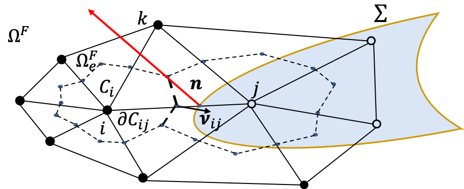
Using the standard characteristic function associated with each control volume , the standard piecewise linear test function associated with each node , and the equivalence between the two functional spaces generated by the two sets of such functions [46], the weak and semi-discrete form of eq. 1 reads
| (5) |
Here, denotes the volume of , denotes the average values of in , and with area-weighted outward normal , denotes the set of nodes connected by an edge to the node , denotes the far-field boundary of the fluid domain with outward unit normal , and denotes the restriction of to .
The integral of the convective term in eq. 5 away from the fluid-structure interface is approximated using Roe’s (or any other similar) approximate Riemann solver [47] equipped with a MUSCL technique [48] and a slope limiter.
The far-field boundary term in eq. 5 is approximated by a standard far-field boundary flux [49, 50].
The computation of the convective term at the fluid-structure interface is done in two steps, as follows:
-
1.
for each active node (in the fluid domain) with an edge that intersects the embedded discrete surface, a local fluid-structure Riemann problem is formulated and solved at the fluid structure interface [25] using the structure velocity at the intersection point. This furnishes an approximate fluid state at the interface.
-
2.
The convective flux along edge in eq. 5 is evaluated by computing the numerical flux
(6)
The integral of the diffusive flux (see eq. 5) in these elements intersected by the fluid- structure interface is evaluated using a the ghost fluid method, as follows:
-
1.
for each active node (in the fluid domain) within an element that intersects the embedded discrete surface, its neighboring nodes – which are associated with but located on the other side of the fluid-structure interface – are first identified, then the velocity and temperature of these neighboring nodes are populated by linear or constant extrapolations.
-
2.
The integral of the diffusive flux is evaluated with a Gaussian quadrature rule, as follows
(7) where is the volume of the element and the terms and are defined as
where denotes the number of nodes attached to the element .
3.2.2 Semi-discretization of the structural equations
The governing system of structural equations (2) is semi-discretized by the FE method using the total Lagrangian method. The resulting semi-discrete equations of equilibrium can be written as
| (8) |
where denotes the symmetric positive definite FE mass matrix, denotes the vector of semi-discrete structural displacements, and denote the vectors of semi-discrete internal and external or flow-induced generalized forces, respectively, and a dot designates a time derivative.
Specifically, the canopy is modeled using a thin-shell element comprising a membrane triangle with corner drilling freedoms [51] and a plate-bending triangle [52]. Both membrane stiffness and bending stiffness are considered even though the membrane stiffness is significantly larger than the bending stiffness. The suspension lines are modeled using Euler-Bernoulli beam elements, which are fixed at the confluent point. The entry vehicle is modeled as a fixed rigid body, and therefore does not need to be represented in the structure model.
3.2.3 Discretization of the governing equations
Finally, the fluid and structural semi-discretizations eqs. 5 and 8 are coupled for FSI simulations using the stability-preserving, second-order, time-accurate, implicit-explicit fluid-structure staggered solution procedure presented in [53]. In this coupled time-discretization algorithm, the semi-discrete fluid subsystem is time-integrated using the second-order three-point implicit backward difference formula and the semi-discrete structural subsystem is time-integrated using the second-order explicit central difference time-integration scheme due to the substantial self-contact of the parachute canopy during its inflation.
3.3 Homogenized porous wall model
The porosity of the parachute canopy affects the stability and drag performance of the parachute [36]. The Ergun equation [54] is generally used to simulate fabric porosity [16, 37]. However, this equation ignores the compressibility of the flow and hence its validity is questionable when applied in the supersonic regime. An alternative homogenized porous wall model is proposed by some of the authors in [55], which takes the compressibility effect into consideration and avoids meshing at the scale of individual pores. This model depends only the void fraction (or porosity) of the parachute fabric and the equivalent pore shape, and has been verified using pore-level resolved direct numerical simulations of typical Mars landing conditions in [55].
Let denotes the void fraction of the parachute fabric, which is estimated from microtomography data [56], specifically for F-111 nylon. To account for the fabric porosity, the convective flux through (see eq. 6) is modified to be the weighted average of the fluid-fluid flux and the fluid-structure flux as follows
| (9) |
The diffusive flux in eq. 7 – which is evaluated using a ghost fluid method – is also modified to account for fabric porosity using a similar technique. Consider the intersected element in fig. 3, let be the populated ghost primitive variables at the node from the node side, and be the real primitive variables at the node . Then the quantities at node used in eq. 7 are replaced by the weighted average
| (10) |
3.4 Fluid-structure interaction at the suspension lines subsystem: master-slave kinematics approach
The presence of suspension lines in the supersonic regime generates shock waves, which have been observed to disrupt the canopy bow shock and exacerbate parachute oscillation [15]. However, suspension lines are generally modeled as one-dimensional beam elements due to their large length-to-diameter ratio, while the fluid subsystem is generally discretized with three-dimensional elements such as tetrahedra, hexahedra and/or triangular prisms. In this scenario, the enforcement of the FSI transmission conditions (eqs. 3 and 4), including the detection of the one-dimensional elements and the definition of associated geometric characteristics such as surface normals, may be difficult or even ambiguous in the context of an embedded boundary framework.
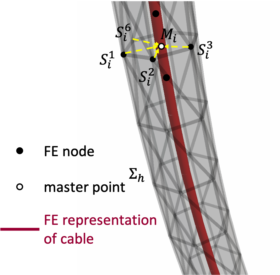
A master-slave kinematic approach was proposed in [57] (see fig. 4), in which the dynamics of the suspension line are captured by the master beam elements, while the real geometry of the cable is represented within the fluid domain using a slave discrete embedded surface . The approach consists of a highly accurate algorithm for computing the embedded surface displacement based on the beam displacement, and an energy-conserving method for transferring distributed forces and moments acting on the embedded surface to the beam elements. The load and motion transfer algorithm can be described as follows:
-
1.
Pair each slave node , , with the closest master point on a beam element (note that the superscript highlights the surjective aspect of the function ). The initial distance vector between these two locations – that is, the distance vector at – is defined by
-
2.
At each time step, compute the displacement and velocity of the slave node as follows
where and denote the interpolated displacement and rotation vectors at the point , and are the interpolated velocity and angular velocity vectors at the point , and is the rotation matrix at which depends on .
-
3.
Compute the force vector at each slave node as follows
where and denote the pressure and viscous stress tensor of the flow at this time step, denotes the outward normal to at this time step, and denotes a local shape function associated with the node . The force vector and moment vector at the point are computed as follows
Finally, the generalized force and moment vectors acting on FE nodes of the beam element are assembled by the load transfer method presented in [58].
Hence, both the flow-induced forces on the cable and the effect of the structural dynamic response of the cable on the nearby flow are taken into account.
3.5 Local contact algorithm
Massive self-contact occurs during parachute inflation, and must be accounted for in order to accurately simulate the parachute inflation dynamics. Moreover, self-penetration causes numerical instability for the fluid solver in the Eulerian computational framework. In this work, the self-contact law for the canopy is enforced by Lagrangian multiplier method using the Algorithms for Contact in a Multiphysics Environment (ACME) library [33]. Furthermore, to accelerate the contact detection and relieve the algorithmic difficulties associated with the reliable detection of interactions for thin two-sided contact surfaces, the contact is enforced between each pair of neighboring gores and only from the outside (i.e., one sided contact). The validity of this simplifying assumption was verified a posteriori by carefully inspecting the solution for self-penetration.
4 Simulation results
The computational framework summarized above is implemented in the massively parallel AERO Suite [59]. It has been verified and validated for several large-scale, highly nonlinear applications associated with marine engineering, aerospace engineering [28], and flapping wings [26]. It is applied here to simulate the DGB parachute inflation described in section 2. Overall, four scenarios are considered in order to investigate different factors that potentially affect the parachute inflation dynamics in the Martian atmosphere. These are listed below
-
1.
Scenario 1: both the interaction of the suspension lines with the flow, and the contribution of bulk viscosity of the fluid medium are neglected. The inflow conditions are the supersonic free-stream Mars atmospheric conditions corresponding to the mortar fire event of the Curiosity mission given by
The Reynolds number based on the canopy diameter and the inflow conditions is .
-
2.
Scenario 2: the interaction of the suspension lines with the flow are accounted for, but the contribution of the bulk viscosity of the fluid medium is neglected. The inflow conditions are the same as for Scenario 1.
-
3.
Scenario 3: both the interaction of the suspension lines with the flow, and the contribution of the bulk viscosity of the fluid medium, are accounted for. The inflow conditions are the same as for Scenario 1.
-
4.
Scenario 4: both the interaction of the suspension lines with the flow, and the contribution of the bulk viscosity of the fluid medium are accounted for, as for Scenario 3. Slightly different inflow conditions corresponding to the line stretch event of the Curiosity mission are used however – specifically,
The background computational fluid domain is initially discretized by a mesh composed of Kuhn simplices [31, 32]. This initial tetrahedral mesh contains vertices and tetrahedra. Adaptive mesh refinement (AMR) [32] based on newest vertex bisection [30, 31] is used, enabling the boundary layer and flow features to be efficiently tracked using a wall distance estimator and a Hessian error indicator, respectively. However, fully resolving the boundary layer of the cable subsystem is generally unaffordable, especially when the cable has large length-to-diameter ratio. To obtain a minimally acceptable resolution, the doubly-intersected edge criterion [57] is applied on each suspension line. Specifically, when an edge of the fluid mesh is intersected twice by the cable’s outer surface – which indicates that the cable is under-resolved in this proximity – the edge is selected for refinement and subsequently bisected. The characteristic mesh sizes near the entry vehicle, suspension lines and the canopy are cm, mm, and cm, respectively, while the mesh size in the wake and near the shock is cm. During the mesh adaptation, the maximum numbers of vertices and tetrahedra reach about and , respectively.
The canopy of the DGB parachute consists of band gores and disk gores. These are discretized here by geometrically nonlinear ANDES thin shell elements [52]. Each one of the 80 suspension lines is discretized by geometrically nonlinear beam elements. The cross-section geometry of each suspension line is assumed to be circular and is represented as a hexagon.
The fluid-structure coupling time-step is initialized to s, but is able to vary during the simulation to preserve stability of the conditionally-stable explicit structural time-integration scheme.
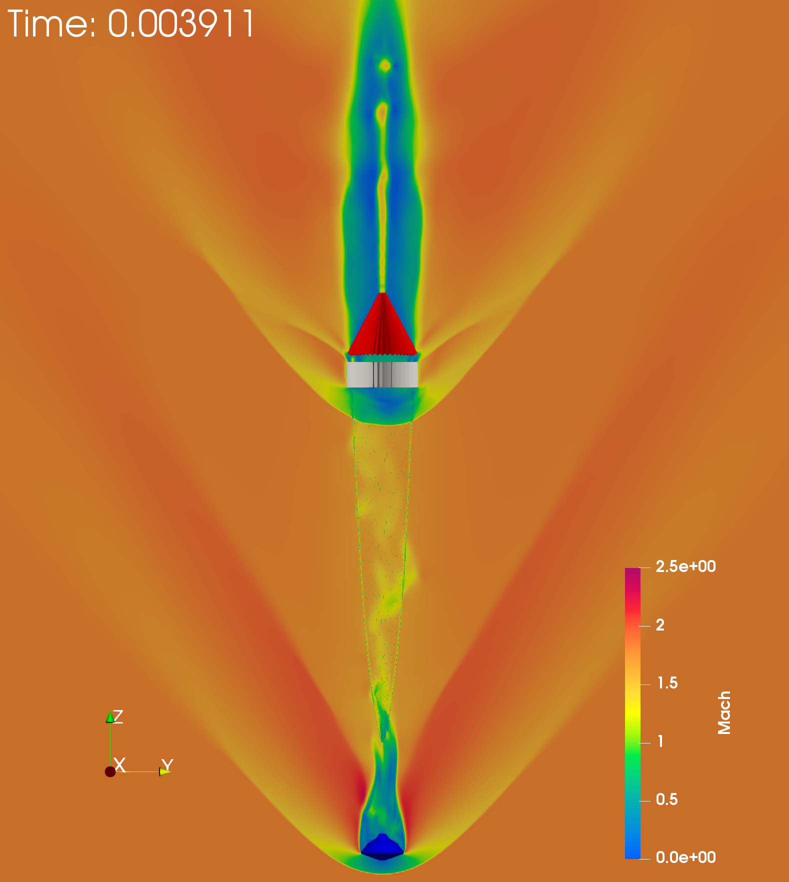
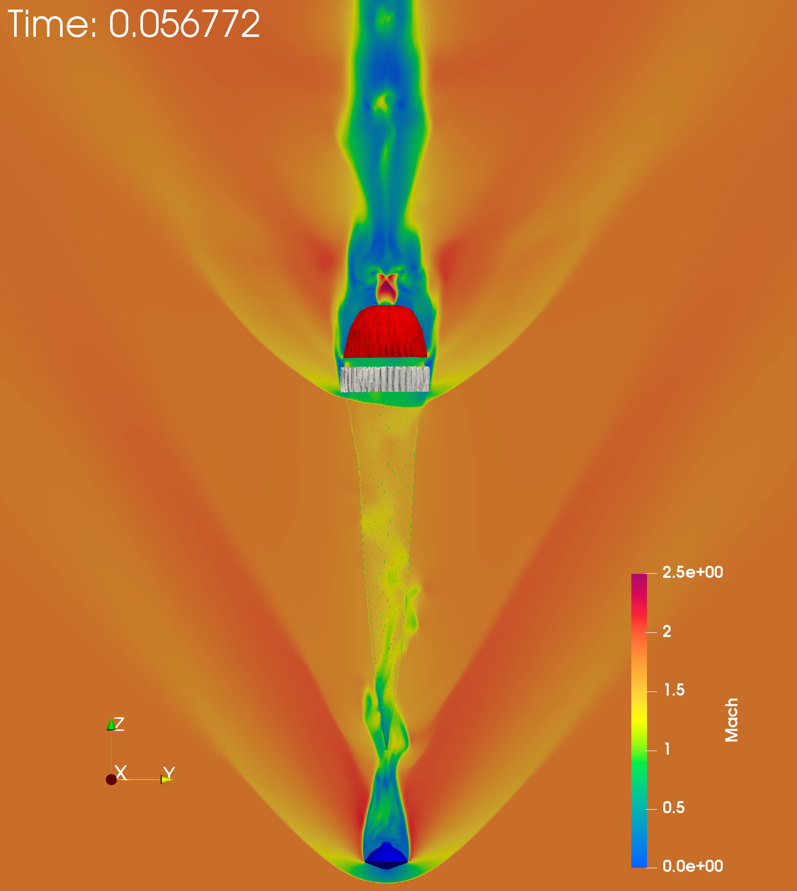
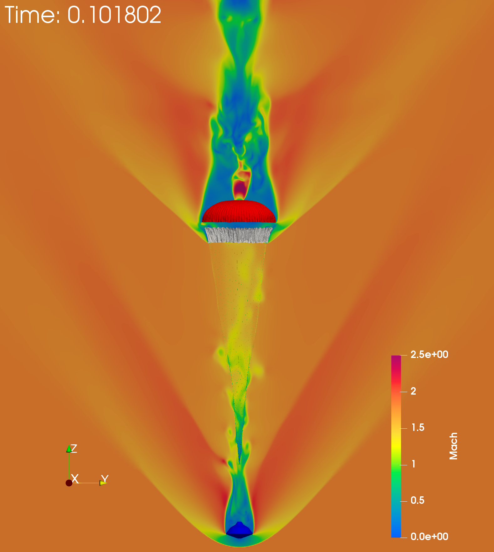
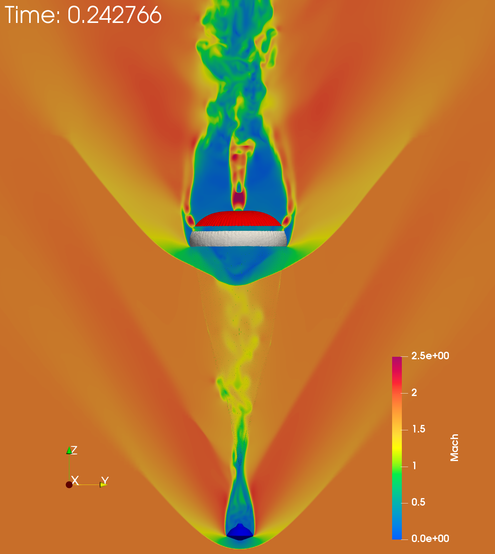
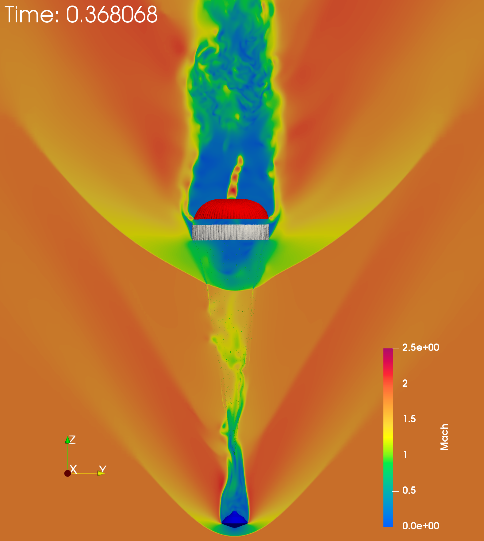
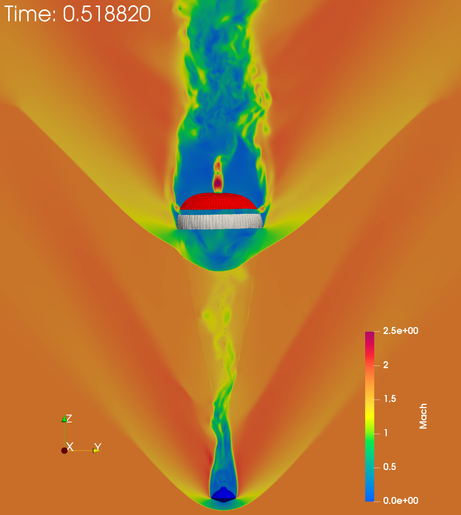
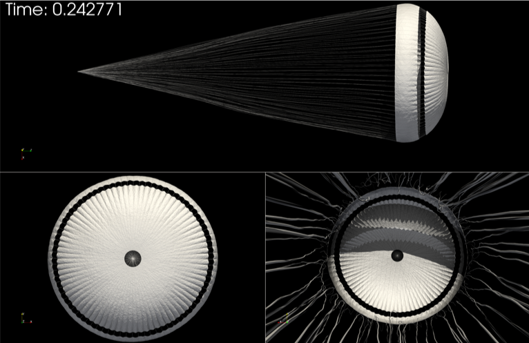
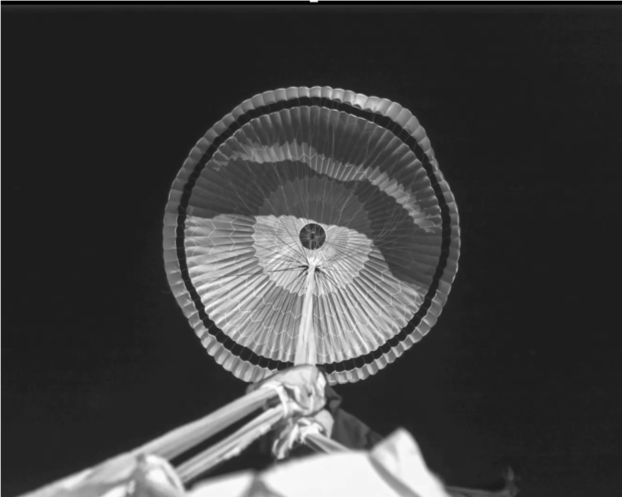
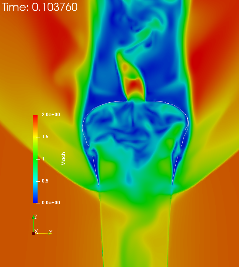
Figure 5 graphically depicts the time-evolution of the parachute deployment and the flow Mach number field for Scenario 2. The inflow is from the bottom of the computational fluid domain. The supersonic inflow first forms a steady bow shock in front of the entry vehicle, then slows down into the subsonic regime behind it, and finally recovers the supersonic regime and forms an unsteady bow shock in front of the canopy. At the beginning of the FSI, the bow shock in the front of the canopy moves toward the canopy (see fig. 5-a and fig. 5-b), the disk part of the canopy begins inflation and reaches full inflation at about s (see fig. 5-c). A supersonic jet (choked flow) appears when the high pressure flow enveloped by the canopy ejects through the disk vent, which intensively interacts with the turbulent wakes behind the canopy. The high pressure flow inside the canopy inflates the band part at around s (see fig. 5-d), which leads to the peak load on the parachute. Following that, the canopy starts to “breathe” and forms several partial collapse cycles. Figure 6-a visualizes the state of the FE structural model including the suspension lines at the moment of the full inflation, and also includes a recent deep space flight test photo of this state for the purpose of qualitative validation (see Figure 6-b).
4.1 Drag performance analysis
Figure 7 reports the time-histories of the measured and predicted drag forces during the Curiosity Mars landing. Note that each force time-history includes contributions of both the suspension lines and the canopy. Although the flight-test data is collected during the first s following the mortar fire, fig. 7 focuses on the time-interval following the suspension line stretch which includes the peak drag. The reported time-histories show that the parachute inflates rapidly, generates a total drag force of roughly kN, then undergoes several partial collapse cycles.
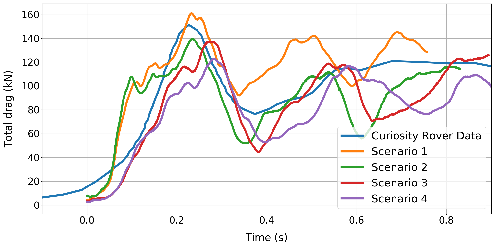
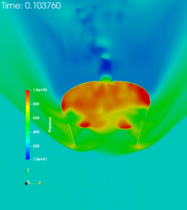
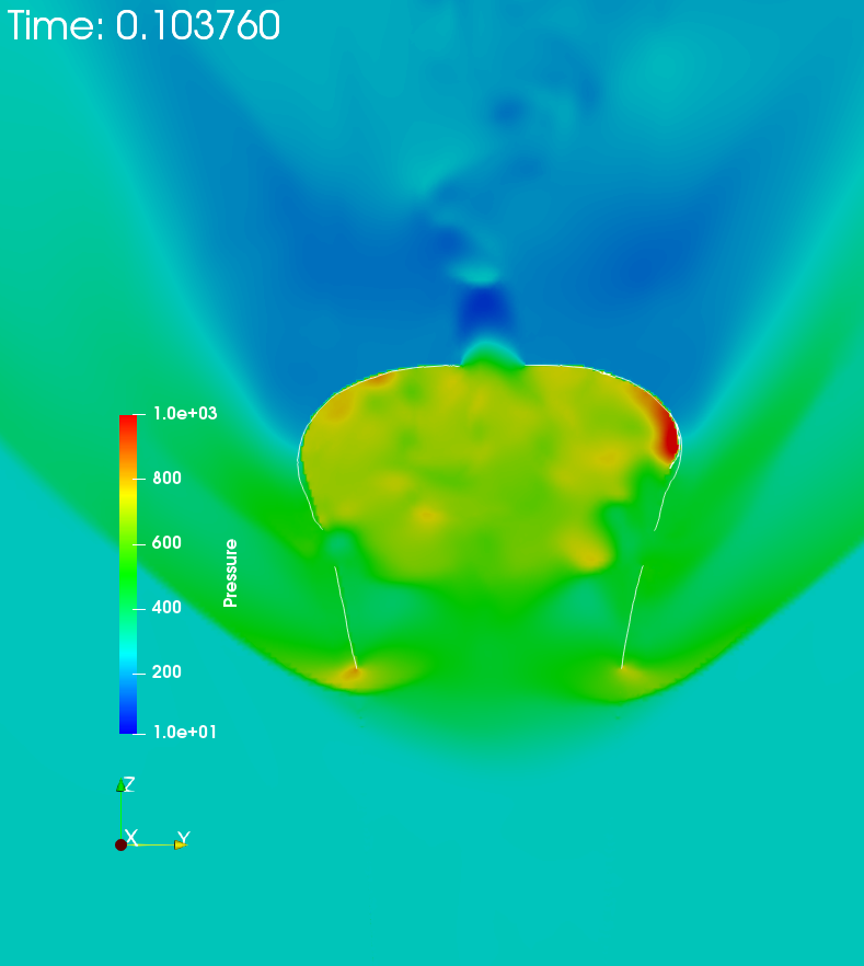
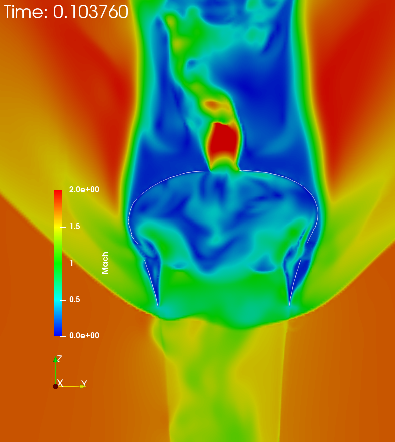
The visualization of the simulated Mach field results (see fig. 5-b and fig. 5-e) shows that the suspension lines create disturbances ahead of the canopy that disrupt the parachute bow shock, promote the mixing of the high pressure and low-pressure flows, and reduce the pressure inside the canopy. Consequently, and as can be inferred from comparison between drag force histories of Scenario 1 (without fluid suspension line interaction) and Scenario 2 (with fluid suspension line interaction) in fig. 7, the interactions of the suspension lines with the nearby high-speed flows reduce the peak drag and the overall drag performance. Figure 7 also shows that as far as the peak of the total drag force is concerned, the effect of the bulk viscosity of the flow medium is rather weak. However, it is significant near the bow shock and jet streams through the vent and the gap, where the volumetric dilatation rate is large. The bulk viscosity effect mainly appears in the drag force histories at about s, when the disk part is inflated along with the approaching of the bow shock. The pressure profiles and Mach profiles of Scenario 2 (without bulk viscosity) and Scenario 3 (with bulk viscosity) at about s are depicted in fig. 8. For Scenario 3, the large bulk viscosity smears the moving bow shock (see fig. 8-d). Hence, the pressure inside the parachute canopy is lower than for Scenario 2. The comparison between Scenario 3 and Scenario 4 reveals the sensitivity of the present parachute inflation simulations with respect to the (uncertain) initial flow conditions.
Overall, the peak drag predictions are in good agreement with the flight test data, even though in all performed AERO Suite simulations, the forebody is assumed to be rigid and stationary, the trim angle is arbitrarily set to zero, and the deceleration process is not accounted for. To the best of our knowledge, the parachute deployment simulations reported here are the first FSI simulations to match the Mars landing data of Curiosity.
4.2 Material failure analysis
Understanding/predicting the onset of the canopy failure that has been observed in several flight tests is another major objective of this research effort. In all numerical simulations discussed above, the canopy material is modeled as a St. Venant-Kirchhoff elastic material, and the von Mises stress is used as the material failure indicator for a preliminary failure analysis, as will be shown below.
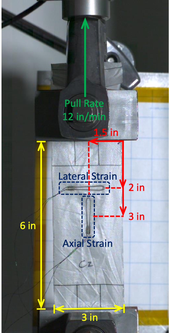
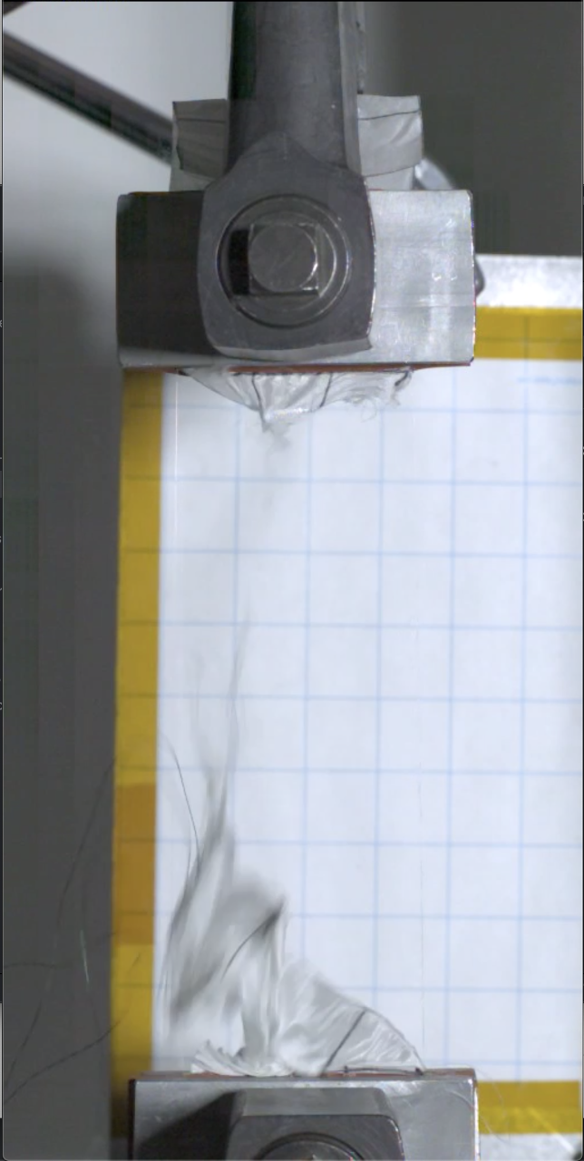
To find the von Mises yield stress at failure, several uniaxial tensile tests of nylon coupons were conducted333The tests were performed on a representative fabric coupon which is close to but not necessarily the same as that used for the Curiosity rover. These tests were also performed to assess a new type of strain gauge, which may create a local stiffness and alter the physical characteristics of the fabric at the point of contact, due to the adhesive.. The specification of the corresponding experimental setup is illustrated in fig. 9-a. The coupon of size in by in is clamped on its bottom edge and pulled from its top edge with a pull rate of in/min until failure. An axial strain sensor is located at the center of the coupon. The coupon is torn to two pieces at about s, with the point of failure located close to the center of the coupon (see fig. 9-b).
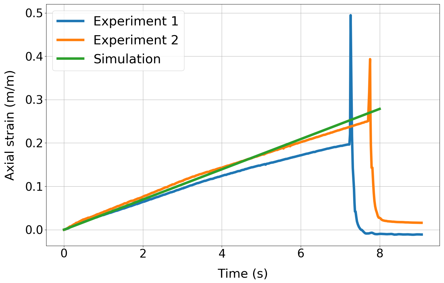
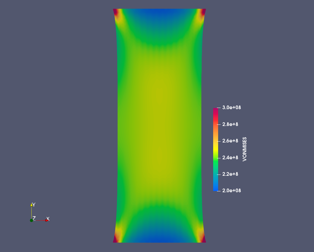
A numerical simulation of this uniaxial test is conducted using the same specifications as above. The measured and predicted axial strains are reported in fig. 10: the predicted axial strain can be seen to match well with the experimental data before material failure. The computed von Mises stress at the point of failure around s was found to be about Pa (see fig. 11). Note the stress concentrations at the four corners are artificial as they are due to the inexact modeling of the boundary conditions, and were therefore neglected.
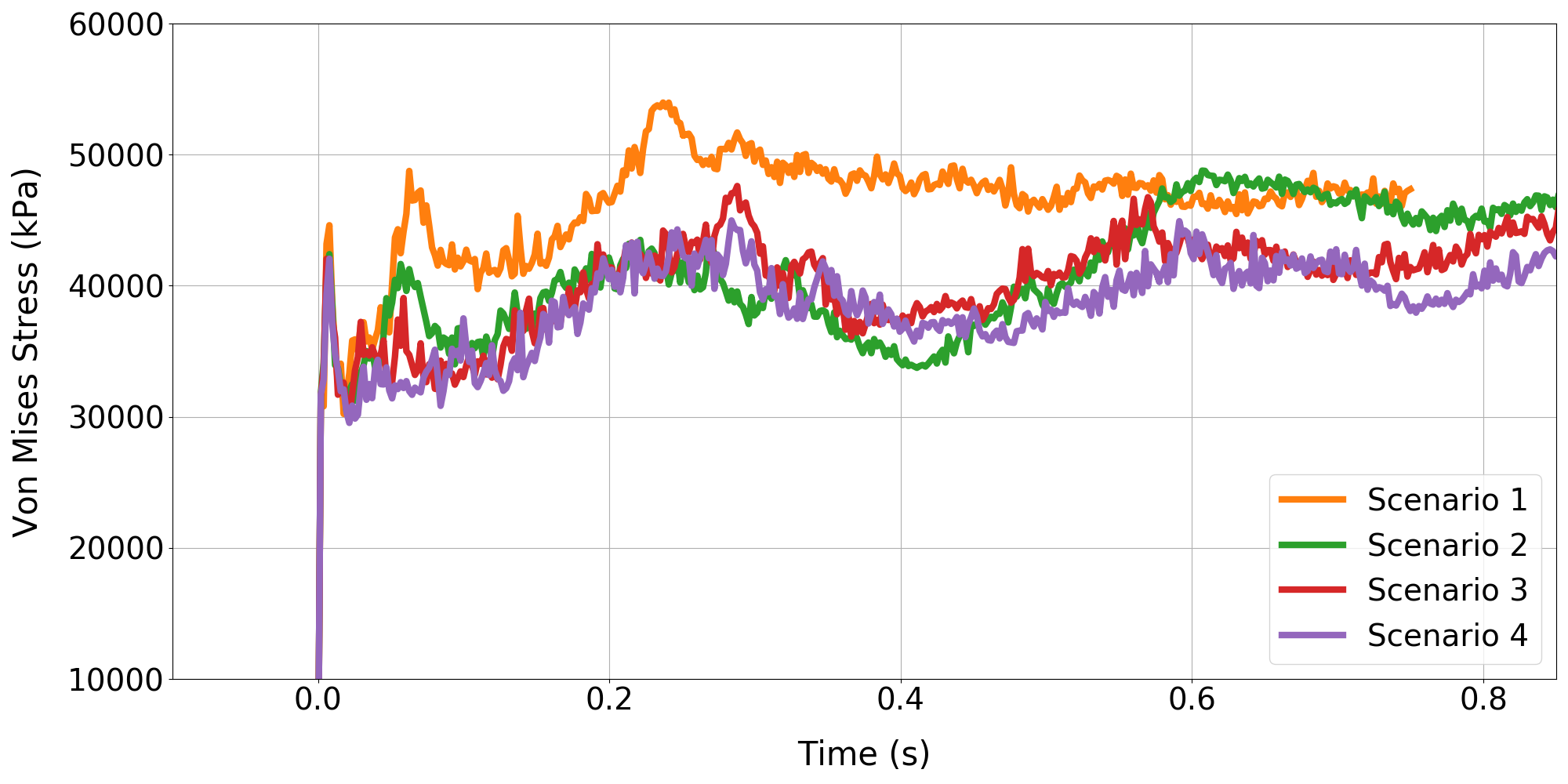
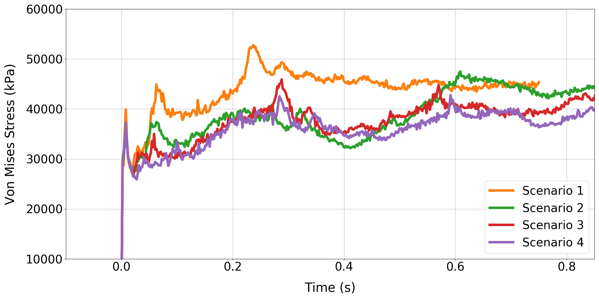
The time-histories of the maximum von Mises stress experienced by the parachute canopy during the simulated inflation process discussed above are reported in fig. 12. Specifically, the maximum von Mises stress and the average of the maximum 80 von Mises stress values, with the exceptions of several outliers artificially caused by local contact self-penetrations, are reported for each case. For all cases, the maximum von Mises stress is reached at or the same time as the peak drag force. Local peaks of this field are obtained along with local peak drags when the disk gores are inflated, or in the partial collapse cycle. The predicted maximum von Mises stress is about Pa. This suggests that the parachute decelerator system of Curiosity survived with a safety factor about 5.
5 Conclusions
This paper presents a high-fidelity multi-physics Eulerian computational framework for Mars landing parachute inflation simulations. A robust embedded boundary approach (FIVER), equipped with efficient adaptive mesh refinement and several novel techniques recently developed specifically for parachute inflation simulations, including a homogenized porous wall model and a suspension line fluid-structure treatment, are discussed. The validation of the framework is presented by simulating the Mars atmosphere entry of the NASA Curiosity Rover [18], i.e., a full-scale parachute inflation simulation in the low-density, low-pressure Mars atmosphere. The canopy breathing, bow shocks and turbulent wake interactions are observed. The effects of fluid-suspension line interactions with the flow and bulk viscosity of the fluid medium, and the sensitivity of the solution with respect to uncertain initial conditions are all highlighted. The predicted and measured drag histories and the first peak forces reach reasonable agreements. To the best of our knowledge, this is the first FSI simulation effort that matches the Mars landing data and suggests a new capability to provide valuable insight for the future supersonic parachute design.
Although not accounted for in the present study, both the motion of the forebody and more sophisticated constitutive modeling of the parachute canopy (incorporating for example multiscale and/or damage modeling) are enabled by the proposed framework and will be considered in future simulations.
Acknowledgments
Daniel Z. Huang, Philip Avery and Charbel Farhat acknowledge partial support by the Jet Propulsion Laboratory (JPL) under Contract JPL-RSA No. 1590208, and partial support by the National Aeronautics and Space Administration (NASA) under Early Stage Innovations (ESI) Grant NASA-NNX17AD02G. Parts of this work were completed at the JPL, California Institute of Technology, under a contract with NASA.
References
- [1] CG Cooley. Viking 75 project: Viking lander system primary mission performance report. NASA Report NASA-CR-145148, FR-3770219, 1977.
- [2] David A Spencer, Robert C Blanchard, Robert D Braun, Pieter H Kallemeyn, and Sam W Thurman. Mars pathfinder entry, descent, and landing reconstruction. Journal of Spacecraft and Rockets, 36(3):357–366, 1999.
- [3] Ravi Prakash, P Dan Burkhart, Allen Chen, Keith A Comeaux, Carl S Guernsey, Devin M Kipp, Leila V Lorenzoni, Gavin F Mendeck, Richard W Powell, Tommaso P Rivellini, et al. Mars science laboratory entry, descent, and landing system overview. In 2008 IEEE Aerospace Conference, pages 1–18. IEEE, 2008.
- [4] Allen Witkowski and Robin Bruno. Mars exploration rover parachute decelerator system program overview. In 17th AIAA Aerodynamic Decelerator Systems Technology Conference and Seminar, page 2100, 2003.
- [5] Douglas S Adams, Allen Witkowski, and Mike Kandis. Phoenix mars scout parachute flight behavior and observations. In 2011 Aerospace Conference, pages 1–8. IEEE, 2011.
- [6] Julian D Maynard. Aerodynamic characteristics of parachutes at mach numbers from 1.6 to 3. NASA Report NASA-TN-D-752, 1961.
- [7] Nickolai Charczenko. Wind-tunnel investigation of drag and stability of parachutes at supersonic speeds. NASA Report, 1964.
- [8] Charles Babish III. Drag let-l staging through modification of supersonic wake views by trailing aerodynamic decelerators. In Aerodynamic Deceleration Systems Conference, page 1506, 1966.
- [9] Anita Sengupta, Leslie Hall, and Mark Wernet. Fluid structure interaction of parachutes in supersonic planetary entry. In 21st AIAA Aerodynamic Decelerator Systems Technology Conference and Seminar, page 2541, 2011.
- [10] Clara O’Farrell, Erich J Brandeau, Christopher Tanner, John C Gallon, Suman Muppidi, and Ian G Clark. Reconstructed parachute system performance during the second ldsd supersonic flight dynamics test. In AIAA Atmospheric Flight Mechanics Conference, page 3242, 2016.
- [11] Jason Rabinovitch, Zhengyu Huang, Philip Avery, Charbel Farhat, Armen Derkevorkian, and Lee D Peterson. Preliminary verification and validation test suite for the cfd component of supersonic parachute deployment fsi simulations. In 2018 AIAA Aerospace Sciences Meeting, page 1542, 2018.
- [12] K Karagiozis, R Kamakoti, F Cirak, and C Pantano. A computational study of supersonic disk-gap-band parachutes using large-eddy simulation coupled to a structural membrane. Journal of Fluids and Structures, 27(2):175–192, 2011.
- [13] John Lingard and Matt Darley. Simulation of parachute fluid structure interaction in supersonic flow. In 18th AIAA Aerodynamic Decelerator Systems Technology Conference and Seminar, page 1607, 2005.
- [14] Michael Barnhardt, Travis Drayna, Ioannis Nompelis, Graham Candler, and William Garrard. Detached eddy simulations of the msl parachute at supersonic conditions. In 19th AIAA Aerodynamic Decelerator Systems Technology Conference and Seminar, page 2529, 2007.
- [15] Anita Sengupta, James Roeder, Richard Kelsch, Mark Wernet, Mike Kandis, and Al Witkowski. Supersonic disk gap band parachute performance in the wake of a viking-type entry vehicle from mach 2 to 2.5. In AIAA Atmospheric Flight Mechanics Conference and Exhibit, page 6217, 2008.
- [16] Zheng Gao, Richard D Charles, and Xiaolin Li. Numerical modeling of flow through porous fabric surface in parachute simulation. AIAA Journal, 55(2):686–690, 2016.
- [17] Zhengyu Huang, Philip Avery, Charbel Farhat, Jason Rabinovitch, Armen Derkevorkian, and Lee D Peterson. Simulation of parachute inflation dynamics using an eulerian computational framework for fluid-structure interfaces evolving in high-speed turbulent flows. In 2018 AIAA Aerospace Sciences Meeting, page 1540, 2018.
- [18] Juan R Cruz, David W Way, Jeremy D Shidner, Jody L Davis, Douglas S Adams, and Devin M Kipp. Reconstruction of the mars science laboratory parachute performance. Journal of Spacecraft and Rockets, 51(4):1185–1196, 2014.
- [19] Cyrill W Hirt, Anthony A Amsden, and JL Cook. An arbitrary lagrangian-eulerian computing method for all flow speeds. Journal of computational physics, 14(3):227–253, 1974.
- [20] Jean Donea, S Giuliani, and Jean-Pierre Halleux. An arbitrary lagrangian-eulerian finite element method for transient dynamic fluid-structure interactions. Computer methods in applied mechanics and engineering, 33(1-3):689–723, 1982.
- [21] Tayfun E Tezduyar and Sunil Sathe. Modelling of fluid–structure interactions with the space–time finite elements: solution techniques. International Journal for Numerical Methods in Fluids, 54(6-8):855–900, 2007.
- [22] Charles S Peskin. Flow patterns around heart valves: a numerical method. Journal of computational physics, 10(2):252–271, 1972.
- [23] Rajat Mittal and Gianluca Iaccarino. Immersed boundary methods. Annu. Rev. Fluid Mech., 37:239–261, 2005.
- [24] Charbel Farhat, Arthur Rallu, and Sriram Shankaran. A higher-order generalized ghost fluid method for the poor for the three-dimensional two-phase flow computation of underwater implosions. Journal of Computational Physics, 227(16):7674–7700, 2008.
- [25] Kevin Wang, Arthur Rallu, J-F Gerbeau, and Charbel Farhat. Algorithms for interface treatment and load computation in embedded boundary methods for fluid and fluid–structure interaction problems. International Journal for Numerical Methods in Fluids, 67(9):1175–1206, 2011.
- [26] V Lakshminarayan, C Farhat, and A Main. An embedded boundary framework for compressible turbulent flow and fluid–structure computations on structured and unstructured grids. International Journal for Numerical Methods in Fluids, 76(6):366–395, 2014.
- [27] Daniel Z Huang, Dante De Santis, and Charbel Farhat. A family of position-and orientation-independent embedded boundary methods for viscous flow and fluid–structure interaction problems. Journal of Computational Physics, 365:74–104, 2018.
- [28] C Farhat, KG Wang, A Main, Stelios Kyriakides, L-H Lee, Krishnaswa Ravi-Chandar, and T Belytschko. Dynamic implosion of underwater cylindrical shells: experiments and computations. International Journal of Solids and Structures, 50(19):2943–2961, 2013.
- [29] KG Wang, P Lea, and C Farhat. A computational framework for the simulation of high-speed multi-material fluid–structure interaction problems with dynamic fracture. International Journal for Numerical Methods in Engineering, 104(7):585–623, 2015.
- [30] William F Mitchell. Unified multilevel adaptive finite element methods for elliptic problems. PhD thesis, University of Illinois at Urbana-Champaign, 1988.
- [31] Rob Stevenson. The completion of locally refined simplicial partitions created by bisection. Mathematics of Computation, 77(261):227–241, 2008.
- [32] Raunak Borker, Daniel Huang, Sebastian Grimberg, Charbel Farhat, Philip Avery, and Jason Rabinovitch. Mesh adaptation framework for embedded boundary methods for computational fluid dynamics and fluid-structure interaction. International Journal for Numerical Methods in Fluids, 2019.
- [33] Martin Wilhelm Heinstein, Micheal W Glass, Arne S Gullerud, Kevin H Brown, Thomas Eugene Voth, and Reese E Jones. Acme algorithms for contact in a multiphysics environment api version 2.2. Technical report, Sandia National Laboratories, 2004.
- [34] Helmut G Heinrich. Aerodynamics of the supersonic guide surface parachute. Journal of Aircraft, 3(2):105–111, 1966.
- [35] Juan Cruz, Raymond Mineck, Donald Keller, and Maria Bobskill. Wind tunnel testing of various disk-gap-band parachutes. In 17th AIAA Aerodynamic Decelerator Systems Technology Conference and Seminar, page 2129, 2003.
- [36] Yongsam Kim and Charles S Peskin. 2–d parachute simulation by the immersed boundary method. SIAM Journal on Scientific Computing, 28(6):2294–2312, 2006.
- [37] Zheng Gao, Richard D Charles, and Xiaolin Li. Numerical modeling of flow through porous fabric surface in parachute simulation. AIAA Journal, 55(2):686–690, 2016.
- [38] Ian G Clark, Allison L Hutchings, Christopher L Tanner, and Robert D Braun. Supersonic inflatable aerodynamic decelerators for use on future robotic missions to mars. Journal of Spacecraft and Rockets, 46(2):340–352, 2009.
- [39] John K Lin, Lauren S Shook, Joanne S Ware, and Joseph V Welch. Flexible material systems testing. NASA Report CR-2010-216854, 2010.
- [40] AW Vreman. An eddy-viscosity subgrid-scale model for turbulent shear flow: Algebraic theory and applications. Physics of fluids, 16(10):3670–3681, 2004.
- [41] George Emanuel. Bulk viscosity of a dilute polyatomic gas. Physics of Fluids A: Fluid Dynamics, 2(12):2252–2254, 1990.
- [42] George Emanuel. Effect of bulk viscosity on a hypersonic boundary layer. Physics of Fluids A: Fluid Dynamics, 4(3):491–495, 1992.
- [43] Rick E Graves and Brian M Argrow. Bulk viscosity: past to present. Journal of Thermophysics and Heat Transfer, 13(3):337–342, 1999.
- [44] Frederike Jaeger, Omar K. Matar, and Erich A. Müller. Bulk viscosity of molecular fluids. The Journal of Chemical Physics, 148(17):174504, 2018.
- [45] Willard E. Meador, Gilda A. Miner, and Lawrence W. Townsend. Bulk viscosity as a relaxation parameter: Fact or fiction? Physics of Fluids, 8(1):258–261, 1996.
- [46] Charbel Farhat, Loula Fezoui, and Stéphane Lanteri. Two-dimensional viscous flow computations on the connecti on machine: Unstructured meshes, upwind schemes and massively parallel computations. Computer Methods in Applied Mechanics and Engineering, 102(1):61–88, 1993.
- [47] Philip L Roe. Approximate riemann solvers, parameter vectors, and difference schemes. Journal of Computational Physics, 43(2):357–372, 1981.
- [48] Bram Van Leer. Towards the ultimate conservative difference scheme. v. a second-order sequel to godunov’s method. Journal of Computational Physics, 32(1):101–136, 1979.
- [49] Joseph L Steger and RF Warming. Flux vector splitting of the inviscid gasdynamic equations with application to finite-difference methods. Journal of Computational Physics, 40(2):263–293, 1981.
- [50] Jean-Michel Ghidaglia and Frédéric Pascal. The normal flux method at the boundary for multidimensional finite volume approximations in cfd. European Journal of Mechanics-B/Fluids, 24(1):1–17, 2005.
- [51] Ken Alvin, M Horacio, Bjørn Haugen, and Carlos A Felippa. Membrane triangles with corner drilling freedoms?i. the eff element. Finite Elements in Analysis and Design, 12(3-4):163–187, 1992.
- [52] Carmelo Militello and Carlos A Felippa. The first andes elements: 9-dof plate bending triangles. Computer Methods in Applied Mechanics and Engineering, 93(2):217–246, 1991.
- [53] C Farhat, A Rallu, K Wang, and T Belytschko. Robust and provably second-order explicit–explicit and implicit–explicit staggered time-integrators for highly non-linear compressible fluid–structure interaction problems. International Journal for Numerical Methods in Engineering, 84(1):73–107, 2010.
- [54] Sabri Ergun and Ao Ao Orning. Fluid flow through randomly packed columns and fluidized beds. Industrial & Engineering Chemistry, 41(6):1179–1184, 1949.
- [55] Daniel Z Huang, Man Long Wong, Sanjiva K Lele, and Charbel Farhat. A homogenized flux-body force approach for modeling porous wall boundary conditions in compressible viscous flows. arXiv preprint arXiv:1907.09632, 2019.
- [56] Francesco Panerai, Arnaud Borner, Joseph C Ferguson, Nagi N Mansour, Eric C Stern, Harold S Barnard, Alastair A MacDowell, and Dilworth Y Parkinson. X-ray micro-tomography applied to nasa’s materials research: heat shields, parachutes and asteroids. NASA report ARC-E-DAA-TN39049, 2017.
- [57] Daniel Z Huang, Philip Avery, and Charbel Farhat. An embedded boundary approach for resolving the contribution of cable subsystems to fully coupled fluid-structure interaction. arXiv preprint arXiv:1908.08382, 2019.
- [58] Charbel Farhat, Michel Lesoinne, and Patrick Le Tallec. Load and motion transfer algorithms for fluid/structure interaction problems with non-matching discrete interfaces: momentum and energy conservation, optimal discretization and application to aeroelasticity. Computer Methods in Applied Mechanics and Engineering, 157(1-2):95–114, 1998.
- [59] Charbel Farhat, Philippe Geuzaine, and Gregory Brown. Application of a three-field nonlinear fluid–structure formulation to the prediction of the aeroelastic parameters of an f-16 fighter. Computers & Fluids, 32(1):3–29, 2003.