Abstract
Test beam data reconstruction is a task that requires a large amount of flexibility due to the heterogeneous data acquisition environments found in these experiments. Often, detectors with different readout schemes such as triggered, frame-based or data driven approaches are combined in a single setup. In order to correlate these data and to reconstruct particle tracks, a versatile event building algorithm and analysis framework is required. Corryvreckan is a flexible, fast and lightweight test beam data reconstruction framework based on a modular concept of the reconstruction chain. It is written in modern C++, requires a minimum of external dependencies and is designed to be fully configurable by the user without the need to alter code. This document presents the user manual of the software as of release version 1.0.
1 Introduction
Corryvreckan is a flexible, fast and lightweight test beam data reconstruction framework based on a modular concept of the reconstruction chain. It is designed to fulfil the requirements for offline event building in complex data-taking environments combining detectors with very different readout architectures. Corryvreckan reduces external dependencies to a minimum by implementing its own flexible but simple data format to store intermediate reconstruction steps as well as final results.
The modularity of the reconstruction chain allows users to add their own functionality (such as event loaders to support different data formats or analysis modules to investigate specific features of detectors), without having to deal with centrally provided functionality, such as coordinate transformations, input and output, parsing of user input, and configuration of the analysis. In addition, tools for batch submission of runs to a cluster scheduler such as HTCondor are provided to ease the (re-)analysis of complete test beam campaigns within a few minutes.
This project strongly profits from the developments undertaken for the Allpix2 project [1, 2]: A Generic Pixel Detector Simulation Framework. Both frameworks employ very similar philosophies for configuration and modularity, and users of one framework will find it easy to get started with the other companion. Some parts of the code base are shared explicitly, such as the configuration class or the module instantiation logic. In addition, the [FileReader] and [FileWriter] modules have profited heavily from their corresponding framework components in Allpix2. The relevant sections of the Allpix2 manual [3, 4] have been adapted for this document.
It is also possible to combine the usage of both software frameworks: data produced by Allpix2 can be read in and analysed with Corryvreckan. This allows, for instance, to perform data/Monte Carlo comparisons when simulating a beam telescope configuration and analysing it with the same parameters as the read test-beam data.
1.1 Scope of this Manual
This document is meant to be the primary user guide for Corryvreckan. It contains both an extensive description of the user interface and configuration possibilities, and a detailed introduction to the code base for potential developers. This manual is designed to:
-
•
Guide new users through the installation;
-
•
Introduce new users to the toolkit for the purpose of running their own test beam data reconstruction and analysis;
-
•
Explain the structure of the core framework and the components it provides to the reconstruction modules;
-
•
Provide detailed information about all modules and how to use and configure them;
-
•
Describe the required steps for implementing new reconstruction modules and algorithms.
More detailed information on the code itself can be found in the Doxygen reference manual [5] available online. No programming experience is required from novice users, but knowledge of (modern) C++ will be useful in the later chapters and may contribute to the overall understanding of the mechanisms.
1.2 Getting Started
An installation guideline is provided in Chapter 2. To get started with the analysis, some working examples can be found in the testing/ directory of the repository. In addition, tutorials are available on https://cern.ch/corryvreckan.
1.3 Support and Reporting Issues
As for most of the software used within the high-energy particle physics community, only limited support on a best-effort basis can be offered for this software. The authors are, however, happy to receive feedback on potential improvements or problems. Reports on issues, questions concerning the software and documentation, and suggestions for improvements are very much appreciated. These should preferably be brought up on the issues tracker of the project which can be found in the repository [6].
1.4 Contributing Code
Corryvreckan is a community project that benefits from active participation in the development and code contributions from users. Users and prospective developers are encouraged to discuss their needs via the issue tracker of the repository [6] to receive ideas and guidance on how to implement a specific feature. Getting in touch with other developers early in the development cycle avoids spending time on features that already exist or are currently under development by other users.
The repository contains a few tools to facilitate contributions and to ensure code quality, as detailed in Chapter 10.
2 Installation
This section aims to provide details and instructions on how to build and install Corryvreckan. An overview of possible build configurations is given. After installing and loading the required dependencies, there are various options to customize the installation of Corryvreckan. This chapter contains details on the standard installation process and information about custom build configurations.
2.1 Supported Operating Systems
Corryvreckan is designed to run without issues on either a recent Linux distribution or Mac OS X. Furthermore, the continuous integration of the project ensures correct building and functioning of the software framework on CentOS 7 (with GCC and LLVM), SLC 6 (with GCC and LLVM) and Mac OS Mojave (OS X 10.14, with AppleClang).
2.2 CMVFS
The software is automatically deployed to CERN’s VM file system (CVMFS) [7] for every new tag. In addition, the master branch is built and deployed every night. New versions are published to the folder /cvmfs/clicdp.cern.ch/software/corryvreckan/ where a new folder is created for every new tag, while updates via the master branch are always stored in the latest folder.
The deployed version currently comprises of all modules that are active by default and do not require additional dependencies. A setup.sh is placed in the root folder of the respective release, which allows all runtime dependencies necessary for executing this version to be set up. Versions for both SLC 6 and CentOS 7 are provided.
2.3 Docker
Docker images are provided for the framework allowing anyone to run analyses without needing to install Corryvreckan on their system. The only required program is the Docker executable as all other dependencies are provided within the Docker images. In order to exchange configuration files and output data between the host system and the Docker container, a folder from the host system should be mounted to the container’s data path /data, which also acts as the Docker WORKDIR location.
The following command creates a container from the latest Docker image in the project registry and starts an interactive shell session with the corry executable already in the $PATH. Here, the current host system path is mounted to the /data directory of the container.
$ docker run --interactive --tty                               \
             --volume "$(pwd)":/data                           \
             --name=corryvreckan                               \
             gitlab-registry.cern.ch/corryvreckan/corryvreckan \
             bash
Alternatively it is also possible to directly start the reconstruction process instead of an interactive shell, e.g. using the following command:
$ docker run --tty --rm                                        \
             --volume "$(pwd)":/data                           \
             --name=corryvreckan                               \
             gitlab-registry.cern.ch/corryvreckan/corryvreckan \
             "corry -c my_analysis.conf"
where an analysis described in the configuration my_analysis.conf is directly executed and the container terminated and deleted after completing the data processing. This closely resembles the behavior of running Corryvreckan natively on the host system. Of course, any additional command line arguments known to the corry executable described in Section 3.1 can be appended.
For tagged versions, the tag name should be appended to the image name, e.g. gitlab-registry.cern.ch/corryvreckan/corryvreckan:v1.0, and a full list of available Docker containers is provided via the project container registry [8].
2.4 Binaries
Binary release tarballs are deployed to EOS to serve as downloads from the web to the directory /eos/project/c/corryvreckan/www/releases. New tarballs are produced for every tag as well as for nightly builds of the master branch, which are deployed with the name corryvreckan-latest-<system-tag>-opt.tar.gz.
2.5 Compilation from Source
The following paragraphs describe how to compile the Corryvreckan framework and its individual analysis and reconstruction modules from the source code.
2.5.1 Prerequisites
The core framework is compiled separately from the individual modules, therefore Corryvreckan has only one required dependency: ROOT 6 (versions below 6 are not supported) [9]. Please refer to [10] for instructions on how to install ROOT. ROOT has several components and to run Corryvreckan the GenVector package is required, a package that is included in the default build.
2.5.2 Downloading the source code
The latest version of Corryvreckan can be downloaded from the CERN Gitlab repository [11]. For production environments, it is recommended to only download and use tagged software versions as many of the available git branches are considered development versions and might exhibit unexpected behavior.
For developers, it is recommended to always use the latest available version from the git master branch. The software repository can be cloned as follows:
$ git clone https://gitlab.cern.ch/corryvreckan/corryvreckan.git
$ cd corryvreckan
2.5.3 Configuration via CMake
Corryvreckan uses the CMake build system to configure, build, and install the core framework as well as all modules. An out-of-source build is recommended: this means CMake should not be directly executed in the source folder. Instead, a build folder should be created from which CMake should be run. For a standard build without any additional flags this entails executing:
$ mkdir build
$ cd build
$ cmake ..
CMake can be run with several extra arguments to change the type of installation. These options can be set with -Doption. The following options are noteworthy:
-
•
CMAKE_INSTALL_PREFIX: The directory to use as a prefix for installing the binaries, libraries, and data. Defaults to the source directory (where the folders bin/ and lib/ are added).
-
•
CMAKE_BUILD_TYPE: The type of build to install, which defaults to RelWithDebInfo (compiles with optimizations and debug symbols). Other possible options are Debug (for compiling with no optimizations, but with debug symbols and extended tracing using the Clang Address Sanitizer library) and Release (for compiling with full optimizations and no debug symbols).
-
•
BUILD_ModuleName: If the specific module ModuleName should be installed or not. Defaults to ON for most modules, however some modules with additional dependencies such as EUDAQ or EUDAQ2 [12, 13] are disabled by default. This set of parameters allows to configure the build for minimal requirements as detailed in Section 2.5.1.
-
•
BUILD_ALL_MODULES: Build all included modules, defaulting to OFF. This overwrites any selection using the parameters described above.
An example of a custom debug build, including the [EventLoaderEUDAQ2] module and with installation to a custom directory, is shown below:
$ mkdir build
$ cd build
$ cmake -DCMAKE_INSTALL_PREFIX=../install/ \
        -DCMAKE_BUILD_TYPE=DEBUG \
        -DBUILD_EventLoaderEUDAQ2=ON ..
It should be noted that the [EventLoaderEUDAQ2] module requires additional dependencies and is therefore not built by default.
2.5.4 Compilation and installation
Compiling the framework is now a single command in the build folder created earlier, where <number_of_cores> is replaced with the number of cores to use for compilation:
$ make -j<number_of_cores>
The compiled (non-installed) version of the executable can be found at src/exec/corry in the build folder. Running Corryvreckan directly without installing can be useful for developers. It is not recommended for normal users, because the correct library and model paths are only fully configured during installation.
To install the library to the selected installation location (defaulting to the source directory of the repository) requires the following command:
$ make install
The binary is now available as bin/corry in the installation directory.
3 The Corryvreckan Framework
Corryvreckan is based on a collection of modules read from a configuration file and an event loop which sequentially processes data from all detectors assigned to one event. In each loop iteration, all modules are executed in the linear order they appear in the configuration file and have access to all data created by previous modules. At the end of the loop iteration, the data cache is cleared and the framework continues with processing the next iteration. This chapter provides basic information about the different components of the framework, its executable as well as the available configuration parameters that are processed on a global level.
3.1 The corry Executable
The Corryvreckan executable corry functions as the interface between the user and the framework. It is primarily used to provide the main configuration file, but also allows options from the main configuration file to be added or overwritten. This is useful for quick testing as well as for batch processing of many runs to be reconstructed.
The executable handles the following arguments:
-
•
-c <file>: Specifies the configuration file to be used for the reconstruction, relative to the current directory. This is the only required argument and the program will fail to start if this argument is not given.
-
•
-l <file>: Specify an additional location, such as a file to forward log output into. This is used as an additional destination alongside the standard output and the location specified in the framework parameters described in Section 3.3.
-
•
-v <level>: Sets the global log verbosity level, overwriting the value specified in the configuration file described in Section 3.3. Possible values are FATAL, STATUS, ERROR, WARNING, INFO and DEBUG, where all options are case-insensitive. The module specific logging level introduced in Section 3.5 is not overwritten.
-
•
-o <option>: Passes extra framework or module options that adds to and/or overwrites those in the main configuration file. This argument may be specified multiple times to add multiple options. Options are specified as key-value pairs in the same syntax as used in the configuration files described in Chapter 4, but the key is extended to include a reference to a configuration section or instantiation in shorthand notation. There are three types of keys that can be specified:
-
–
Keys to set framework parameters: These have to be provided in exactly the same way as they would be in the main configuration file (a section does not need to be specified). An example to overwrite the standard output directory would be corry -c <file> -o output_directory="run123456".
-
–
Keys for module configurations: These are specified by adding a dot (.) between the module and the key as it would be given in the configuration file (thus module.key). An example to overwrite the number of hits required for accepting a track candidate would be corry-c<file>-oTracking4D.min_hits_on_track=5.
-
–
Keys to specify values for a particular module instantiation: The identifier of the instantiation and the name of the key are split by a dot (.), in the same way as for keys for module configurations (thus identifier.key). The unique identifier for a module can contain one or more colons (:) to distinguish between various instantiations of the same module. The exact name of an identifier depends on the name of the detector. An example to change the neighbor pixel search radius of the clustering algorithm for a particular instantiation of the detector named my_dut could be corry-c<file>-oClustering4D:my_dut.neighbour_radius_row=2.
Note that only the single argument directly following the -o is interpreted as the option. If there is whitespace in the key-value pair this should be properly enclosed in quotation marks to ensure that the argument is parsed correctly.
-
–
-
•
-g <option>: Passes extra detector options that are added to and/or overwritten in the detector configuration file. This argument can be specified multiple times to add multiple options. The options are parsed in the same way as described above for module options, but only one type of key can be specified to overwrite an option for a single detector. These are specified by adding a dot (.) between the detector and the key as it would be given in the detector configuration file (thus detector.key). An example to change the orientation of a particular detector named detector1 would be corry -c <file> -g detector1.orientation=0deg,0deg,45deg.
No direct interaction with the framework is possible during the reconstruction. Signals can be sent using keyboard shortcuts to terminate the run, either gracefully or with force. The executable understands the following signals:
-
•
SIGINT (CTRL+C): Request a graceful shutdown of the reconstruction. This means the event currently being processed is finished, while all other events requested in the configuration file are ignored. After finishing the event, the finalization stage is executed for every module to ensure all modules finish properly.
-
•
SIGTERM: Same as SIGINT, request a graceful shutdown of the reconstruction. This signal is emitted e.g. by the kill command or by cluster computing schedulers to ask for a termination of the job.
-
•
SIGQUIT (CTRL+\): Forcefully terminates the framework. It is not recommended to use this signal as it will normally lead to the loss of all generated data. This signal should only be used when graceful termination is not possible.
3.2 The Clipboard
The clipboard is the framework infrastructure for temporarily storing information during the event processing. Every module can access the clipboard to both read and write information. Collections or individual elements on the clipboard are accessed via their data type, and an optional key can be used in addition to identify them with a certain detector by its name.
The clipboard consists of three parts: the event, a temporary data storage, and a persistent storage space.
3.2.1 The Event
The event is the central element storing meta-information about the data currently processed. This includes the time frame (or data slice) within which all data are located as well as trigger numbers associated with these data. New data to be added are always compared to the event on the clipboard to determine whether they should be discarded, included, or buffered for later use. A detailed description of the event building process is provided in Chapter 5.
3.2.2 Temporary Data Storage
The temporary data storage is only available during the processing of each individual event. It is automatically cleared at the end of the event processing and has to be populated with new data in the new event to be processed.
The temporary storage acts as the main data structure to communicate information between different modules and can hold multiple collections of Corryvreckan objects such as pixel hits, clusters, or tracks. In order to be able to flexibly store different data types on the clipboard, the access methods for the temporary data storage are implemented as templates, and vectors of any data type deriving from corry::Object can be stored and retrieved.
3.2.3 Persistent Storage
The persistent storage is not cleared at the end of processing each event and can be used to store information used in multiple events. Currently this storage only allows for the caching of double-precision floating point numbers.
3.3 Global Framework Parameters
The Corryvreckan framework provides a set of global parameters that control and alter its behavior. These parameters are inherited by all modules. The currently available global parameters are:
-
•
detectors_file: Location of the file describing the detector configuration described in Section 4.3. The only required global parameter as the framework will fail to start if it is not specified. This parameter can take multiple paths; all provided files will be combined into one geometry description of the setup.
-
•
detectors_file_updated: Location of the file that the (potentially) updated detector configuration should be written into. If this file does not already exist, it will be created. If the same file is given as for detectors_file, the file is overwritten. If no file is specified using this parameter then the updated geometry is not written to file.
-
•
histogram_file: Location of the file where the ROOT output histograms of all modules will be written to. The file extension .root will be appended if not present. Directories within the ROOT file will be created automatically for all modules.
-
•
number_of_events: Determines the total number of events the framework will process, where negative numbers allow for the processing of all data available. After reaching the specified number of events, the reconstruction is stopped. Defaults to .
-
•
number_of_tracks: Determines the total number of tracks the framework should reconstruct, where negative numbers indicate that there is no limit on the number of reconstructed tracks. After reaching the specified number of events, the reconstruction is stopped. Defaults to .
-
•
run_time: Determines the wall-clock time of data acquisition the framework should reconstruct up until. Negative numbers indicate that there is no limit on the time slice to reconstruct. Defaults to .
-
•
log_level: Specifies the lowest log level that should be reported. Possible values are FATAL, STATUS, ERROR, WARNING, INFO, and DEBUG, where all options are case-insensitive. Defaults to the INFO level. More details and information about the log levels, including how to change them for a particular module, can be found in Section 3.5. Can be overwritten by the -v parameter on the command line (see Section 3.1).
-
•
log_format: Determines the log message format to be displayed. Possible options are SHORT, DEFAULT, and LONG, where all options are case-insensitive. More information can be found in Section 3.5.
-
•
log_file: File where the log output will be written, in addition to the standard printing (usually the terminal). Another (additional) location to write to can be specified on the command line using the -l parameter (see Section 3.1).
-
•
library_directories: Additional directories to search in for module libraries, before searching the default paths.
-
•
output_directory: Directory to write all output files into. Subdirectories are created automatically for all module instantiations. This directory will also contain the histogram_file specified via the parameter described above. Defaults to the current working directory with the subdirectory output/ attached.
-
•
purge_output_directory: Decides whether the content of an already existing output directory is deleted before a new run starts. Defaults to false, i.e. files are kept but will be overwritten by new files created by the framework.
-
•
deny_overwrite: Forces the framework to abort the run and throw an exception when attempting to overwrite an existing file. Defaults to false, i.e. files are overwritten when requested. This setting is inherited by all modules, but can be overwritten in the configuration section of each of the modules.
3.4 Modules and the Module Manager
Corryvreckan is a modular framework and one of the core ideas is to partition functionality into independent modules that can be inserted or removed as required. These modules are located in the subdirectory src/modules/ of the repository, with the name of the directory as the unique name of the module. The suggested naming scheme is CamelCase, thus an example module name would be [OnlineMonitor]. Any specifying part of a module name should precede the functional part of the name, e.g. [EventLoaderCLICpix2] rather than [CLICpix2EventLoader]. There are three different kinds of modules that can be defined:
-
•
Global: Modules for which a single instance runs, irrespective of the number of detectors.
-
•
Detector: Modules that are concerned with only a single detector at a time. These are then replicated for all required detectors.
-
•
DUT: Similar to the Detector modules, these modules run for a single detector. However, they are only replicated if the respective detector is marked as device-under-test (DUT).
The type of module determines the constructor used, the internal unique name, and the supported configuration parameters. For more details about the instantiation logic for the different types of modules, see Section 3.4.3.
Furthermore, detector modules can be restricted to certain types of detectors. This allows the framework to automatically determine for which of the given detectors the respective module should be instantiated. For example, the [EventLoaderCLICpix2] module will only be instantiated for detectors with the correct type CLICpix2 without any additional configuration effort required by the user. This procedure is described in more detail in Section 9.1.1.
3.4.1 Module Status Codes
The run() function of each module returns a status code to the module manager to indicate the status of the module. These codes can be used to e.g. request the end of the current run or to signal problems in data processing. The following status codes are currently supported:
-
Success: Indicates that the module successfully finished processing all data. The framework continues with the next module.
-
NoData: Indicates that the respective module did not find any data to process. The framework continues with the next module.
-
DeadTime: Indicates that the detector handled by the respective module is currently in data acquisition dead time. The framework skips all remaining modules for this event and continues with the subsequent event. By employing this method, measurements such as efficiency are not affected by known inefficiencies during detector dead times.
-
EndRun: Allows the module to request a premature end of the run. This can e.g. be used by alignment modules to stop the run after they have accumulated enough tracks for the alignment procedure. The framework executes all remaining modules for the current event and then enters the finalization stage.
-
Failure: Indicates that there was a severe problem when processing data in the respective module. The framework skips all remaining modules for this event and enters the finalization stage.
3.4.2 Execution Order
Modules are executed in the order in which they appear in the configuration file; the sequence is repeated for every time frame or event. If one module in the chain raises e.g. a DeadTime status, the processing of the next event is begun without executing the remaining modules for the current event.
The execution order is of special importance in the event building process, since the first module will always have to define the event while subsequent event loader modules will have to adhere to the time frame defined by the first module. A complete description of the event building process is provided in Chapter 5.
This behavior should also be taken into account when choosing the order of modules in the configuration file, since e.g. data from detectors catered by subsequent event loaders is not processed and hit maps are not updated if an earlier module requested to skip the rest of the module chain.
3.4.3 Module instantiation
Modules are dynamically loaded and instantiated by the Module Manager. They are constructed, initialized, executed, and finalized in the linear order in which they are defined in the configuration file. For this reason, the configuration file should follow the order of the real process. For each section in the main configuration file (see Chapter 4 for more details), a corresponding library is searched for which contains the module (the exception being the global framework section). Module libraries are always named following the scheme libCorryvreckanModuleModuleName, reflecting the ModuleName configured via CMake. The module search order is as follows:
-
1.
Modules already loaded from an earlier section header
-
2.
All directories in the global configuration parameter library_directories in the provided order, if this parameter exists.
-
3.
The internal library paths of the executable, which should automatically point to the libraries that are built and installed together with the executable. These library paths are stored in RPATH on Linux, see the next point for more information.
-
4.
The other standard locations to search for libraries depending on the operating system. Details about the procedure Linux follows can be found in [14].
If the loading of the module library is successful, the module is checked to determine if it is a global, detector, or DUT module. A single module may be called multiple times in the configuration with overlapping requirements (such as a module that runs on all detectors of a given type, followed by the same module but with different parameters for one specific detector, also of this type). Hence the Module Manager must establish which instantiations to keep and which to discard. The instantiation logic determines a unique name and priority for every instantiation. Internally these are handled as numerical values, where a lower number indicates a higher priority. The name and priority for the instantiation are determined differently for the two types of modules:
-
•
Global: Name of the module, the priority is always high.
-
•
Detector/DUT: Combination of the name of the module and the name of detector this module is executed for. If the name of the detector is specified directly by the name parameter, the priority is high. If the detector is only matched by the type parameter, the priority is medium. If the name and type are both unspecified and the module is instantiated for all detectors, the priority is low.
In the end, only a single instance for every unique name is allowed. If there are multiple instantiations with the same unique name, the instantiation with the highest priority is kept. If multiple instantiations with the same unique name and the same priority exist, an exception is raised.
3.5 Logging and Verbosity Levels
Corryvreckan is designed to identify mistakes and implementation errors as early as possible and to provide the user with clear indications of the location and cause the problem. The amount of feedback can be controlled using different log levels, which are inclusive, i.e. lower levels also include messages from all higher levels. The global log level can be set using the global parameter log_level. The log level can be overridden for a specific module by adding the log_level parameter to the respective configuration section. The following log levels are supported:
-
•
FATAL: Indicates a fatal error that will lead to the direct termination of the application. Typically only emitted in the main executable after catching exceptions, as they are the preferred way of fatal error handling. An example of a fatal error is an invalid value for an existing configuration parameter.
-
•
STATUS: Important information about the status of the reconstruction. Is only used for messages that have to be logged in every run, such as initial information on the module loading, opened data files, and the current progress of the run.
-
•
ERROR: Severe error that should not occur during a normal, well-configured reconstruction. Frequently leads to a fatal error and can be used to provide extra information that may help in finding the problem. For example, it is used to indicate the reason a dynamic library cannot be loaded.
-
•
WARNING: Indicate conditions that should not occur normally and possibly lead to unexpected results. The framework will however continue without problems after a warning. A warning is, for example, issued to indicate that a calibration file for a certain detector cannot be found and that the reconstruction is therefore performed with uncalibrated data.
-
•
INFO: Information messages about the reconstruction process. Contains summaries of the reconstruction details for every event and for the overall run. This should typically produce at maximum one line of output per event and module.
-
•
DEBUG: In-depth details about the progress of the reconstruction, such as information on every cluster formed or on track fitting results. Produces large volumes of output per event and should therefore only be used for debugging the reconstruction process.
-
•
TRACE: Messages to trace what the framework or a module is currently doing. Unlike the DEBUG level, it does not contain any direct information about the physics but rather indicates which part of the module or framework is currently running. Mostly used for software debugging or determining performance bottlenecks in the reconstruction.
It is not recommended to set the log_level higher than WARNING in a typical reconstruction as important messages may be missed. Setting too low logging levels should also be avoided since printing many log messages will significantly slow down the reconstruction.
The logging system supports several formats for displaying the log messages. The following formats are supported via the global parameter log_format or the individual module parameter with the same name:
-
•
SHORT: Displays the data in a short form. Includes only the first character of the log level followed by the configuration section header and the message.
-
•
DEFAULT: The default format. Displays the system time, log level, section header, and the message itself.
-
•
LONG: Detailed logging format. Displays all of the above but also indicates the source code file and line where the log message was produced. This can help when debugging modules.
3.6 Coordinate Systems
Local coordinate systems for each detector and a global frame of reference for the full setup are defined. The global coordinate system is chosen as a right-handed Cartesian system, and the rotations of individual devices are performed around the geometrical center of their sensor. Here, the beam direction defines the positive z-axis at the origin of the x-y-plane. The origin along the z-axis is fixed by the placement of the detectors in the geometry of the setup.
Local coordinate systems for the detectors are also right-handed Cartesian systems, with the x- and y-axes defining the sensor plane. The origin of this coordinate system is the center of the lower left pixel in the grid, i.e. the pixel with indices (0,0). This simplifies calculations in the local coordinate system as all positions can either be stated in absolute numbers or in fractions of the pixel pitch.
4 Configuration Files
The framework is configured with human-readable key-value based configuration files. The configuration format consists of section headers within and brackets, and a global section without a header at the beginning. Each of these sections contains a set of key-value pairs separated by the = character. Comments are indicated using the hash symbol (#).
Since configuration files are highly user-specific and do not directly belong to the Corryvreckan framework, they should not be stored in the Corryvreckan repository. However, working examples can be found in the testing/ directory of the repository.
Corryvreckan can handle any file extensions for geometry and configuration files. The examples, however, follow the convention of using the extension *.conf for both the detector and configuration files.
The framework has two required layers of configuration files:
-
•
The main configuration: It is passed directly to the binary and contains both the global framework configuration and the list of modules to instantiate, together with their configuration.
-
•
The detector configuration: Passed to the framework to determine the geometry. Describes the detector setup and contains the position, orientation and type of all detectors along with additional properties crucial for the reconstruction.
In the following paragraphs, the available types and the unit system are explained and an introduction to the different configuration files is given.
4.1 Parsing types and units
The Corryvreckan framework supports the use of a variety of types for all configuration values. The module requesting the configuration key specifies how the value type should be interpreted. An error will be raised if either a necessary key is not specified in the configuration file, the conversion to the desired type is not possible, or if the given value is outside the domain of possible options. Please refer to the module documentation in Chapter 8 for the list of module parameters and their types. The value is parsed in an intuitive manner, however a few special rules do apply:
-
•
If the value is a string, it may be enclosed by a single pair of double quotation marks ("), which are stripped before passing the value to the module(s). If the string is not enclosed by quotation marks, all whitespace before and after the value is erased. If the value is an array of strings, the value is split at every whitespace or comma (,) that is not enclosed in quotation marks.
-
•
If the value is a boolean, either numerical (0, 1) or textual (false, true) representations are accepted.
-
•
If the value is a relative path, that path will be made absolute by adding the absolute path of the directory that contains the configuration file where the key is defined.
-
•
If the value is an arithmetic type, it may have a suffix indicating the unit. The list of base units is shown in Table 1.
The internal base units of the framework are not chosen for user convenience, but for maximum precision of the calculations and to avoid the necessity of conversions in the code. Combinations of base units can be specified by using the multiplication sign * and the division sign / that are parsed in linear order (thus should be specified as ). The framework assumes the default units (as given in Table 1) if the unit is not explicitly specified.
If no units are specified, values will always be interpreted in the base units of the framework. In some cases this can lead to unexpected results. E.g. specifying a pixel pitch as pixel_pitch=55,55 results in a detector with a pixel size of . Therefore, it is strongly recommended to always specify the units explicitly for all parameters that are not dimensionless in the configuration files.
| Quantity | Default unit | Auxiliary units |
| Length | mm (millimeter) | nm (nanometer) |
| um (micrometer) | ||
| cm (centimeter) | ||
| dm (decimeter) | ||
| m (meter) | ||
| km (kilometer) | ||
| Time | ns (nanosecond) | ps (picosecond) |
| us (microsecond) | ||
| ms (millisecond) | ||
| s (second) | ||
| Energy | MeV (megaelectronvolt) | eV (electronvolt) |
| keV (kiloelectronvolt) | ||
| GeV (gigaelectronvolt) | ||
| Temperature | K (kelvin) | — |
| Charge | e (elementary charge) | ke (kiloelectrons) |
| fC (femtocoulomb) | ||
| C (coulomb) | ||
| Voltage | MV (megavolt) | V (volt) |
| kV (kilovolt) | ||
| Magnetic field strength | T (tesla) | mT (millitesla) |
| Angle | rad (radian) | deg (degree) |
| mrad (milliradian) |
Examples of specifying key-values pairs of various types are given below:
4.1.1 File format
Throughout the framework, a simplified version of TOML [15] is used as standard format for configuration files. The format is defined as follows:
-
1.
All whitespace at the beginning or end of a line are stripped by the parser. In the rest of this format specification, line refers to the line with this whitespace stripped.
-
2.
Empty lines are ignored.
-
3.
Every non-empty line should start with either #, [ or an alphanumeric character. Every other character should lead to an immediate parse error.
-
4.
If the line starts with a hash character (#), it is interpreted as comment and all other content on that line is ignored.
-
5.
If the line starts with an open square bracket ([), it indicates a section header (also known as configuration header). The line should contain a string with alphanumeric characters and underscores indicating the header name, followed by a closing square bracket (]) to end the header. After any number of ignored whitespace characters there could be a # character. If this is the case, the rest of the line is handled as specified in point 3. Otherwise, there should not be any other character on the line that is not whitespace. Any line that does not comply to these specifications should lead to an immediate parse error. Multiple section headers with the same name are allowed. All key-value pairs in the line following this section header are part of this section until a new section header is started.
-
6.
If the line starts with an alphanumeric character, the line should indicate a key-value pair. The beginning of the line should contain a string of alphabetic characters, numbers, dots (.), colons (:), and/or underscores (_), but it may only start with an alphanumeric character. This string indicates the ’key’. After an optional number of ignored whitespace, the key should be followed by an equality sign (). Any text between the and the first # character not enclosed within a pair of single or double quotes (’ or ") is known as the non-stripped string. Any character after the # is handled as specified in point 3. If the line does not contain any non-enclosed # character, the value ends at the end of the line instead. The ’value’ of the key-value pair is the non-stripped string with all whitespace in front and at the end stripped. The value may not be empty. Any line that does not comply to these specifications should lead to an immediate parse error.
-
7.
The value may consist of multiple nested dimensions that are grouped by pairs of square brackets ([ and ]). The number of square brackets should be properly balanced, otherwise an error is raised. Square brackets that should not be used for grouping should be enclosed in quotation marks. Every dimension is split at every whitespace sequence and comma character (,) not enclosed in quotation marks. Implicit square brackets are added to the beginning and end of the value, if these are not explicitly added. A few situations require the explicit addition of outer brackets such as matrices with only one column element, i.e. with dimension 1xN.
-
8.
The sections of the value that are interpreted as separate entities are named elements. For a single value the element is on the zeroth dimension, for arrays on the first dimension, and for matrices on the second dimension. Elements can be forced by using quotation marks, either single or double quotes (’ or "). The number of both types of quotation marks should be properly balanced, otherwise an error is raised. The conversion of the elements to the actual type is performed when accessing the value.
-
9.
All key-value pairs defined before the first section header are part of a zero-length empty section header.
4.1.2 Accessing parameters
Values are accessed via the configuration object. In the following example, the key is a string called key, the object is named config and the type TYPE is a valid C++ type that the value should represent. The values can be accessed via the following methods:
Conversions to the requested type are using the from_string and to_string methods provided by the framework string utility library. These conversions largely follow standard C++ parsing, with one important exception. If (and only if) the value is retrieved as a C/C++ string and the string is fully enclosed by a pair of " characters, these are stripped before returning the value. Strings can thus also be provided with or without quotation marks.
It should be noted that a conversion from string to the requested type is a comparatively heavy operation. For performance-critical sections of the code, one should consider fetching the configuration value once and caching it in a local variable.
4.2 Main configuration
The main configuration file consists of a set of sections specifying the modules to be used. All modules are executed in the linear order in which they are defined. There are a few section names that have a special meaning in the main configuration, namely the following:
-
•
The global (framework) header sections: These are all zero-length section headers (including the one at the beginning of the file) and all sections marked with the header [Corryvreckan] (case-insensitive). These are combined and accessed together as the global configuration, which contains all parameters of the framework itself as described in Section 3.3. All key-value pairs defined in this section are also inherited by all individual configurations as long the key is not defined in the module configuration itself. This is encouraged for module parameters used in multiple modules.
-
•
The ignore header sections: All sections with name [Ignore] are ignored. Key-value pairs defined in the section, as well as the section itself, are discarded by the parser. These section headers are useful for quickly enabling and disabling individual modules by replacing their actual name by an ignore section header.
All other section headers are used to instantiate modules of the respective name. Installed module libraries are loaded automatically at startup. Parameters defined under the header of a module are local to that module and are not inherited by other modules.
An example for a valid albeit illustrative Corryvreckan main configuration file is:
4.3 Detector configuration
The detector configuration file consists of a set of sections that describe the detectors in the setup. Each section starts with a header describing the name used to identify the detector; all names are required to be unique. Every detector should contain all of the following parameters:
-
•
The role parameter is an array of strings indicating the function(s) of the respective detector. This can be dut, reference (ref), auxiliary (aux), or none, where the latter is the default. With the default role, the respective detector participates in tracking but is neither used as reference plane for alignment and correlations, nor treated as DUT. In a reference role, the detector is used as anchor for relative alignments and its position and orientation is used for comparison when producing correlation and residual plots. As DUT, the detector is by default excluded from tracking, and all DUT-type modules are executed for this detector. As an auxiliary device, the detector may provide additional information but does not partake in the reconstruction. This is useful to e.g. include trigger logic units (TLUs) providing only timing information.
There always has to be exactly one reference detector in the setup. For setups with a single detector only, the role should be configured as dut,reference for the detector to act as both. Auxiliary devices cannot have any other role simultaneously.
-
•
The type parameter is a string describing the type of detector, e.g. Timepix3 or CLICpix2. This value might be used by some modules to distinguish between different types.
-
•
The position in the world frame. This is the position of the geometric center of the sensor given in world coordinates as X, Y and Z as defined in Section 3.6.
-
•
An orientation_mode that determines the way that the orientation is applied. This can be either xyz, zyx, or zxz, where xyz is used as default if the parameter is not specified. Three angles are expected as input, which should always be provided in the order in which they are applied.
-
–
The xyz option uses extrinsic Euler angles to apply a rotation around the global axis, followed by a rotation around the global axis, and finally a rotation around the global axis.
-
–
The zyx option uses the extrinsic Z-Y-X convention for Euler angles, also known as Pitch-Roll-Yaw or 321 convention. The rotation is represented by three angles describing an initial rotation of an angle (yaw) about the axis, followed by a rotation of an angle (pitch) about the initial axis, followed by a third rotation of an angle (roll) about the initial axis.
-
–
The zxz option uses the extrinsic Z-X-Z convention for Euler angles. This option is also known as the 3-1-3 or the "x-convention" and the most widely used definition of Euler angles [16].
It is highly recommended to always explicitly state the orientation mode, rather than relying on the default configuration, to avoid unwanted behaviour.
-
–
-
•
The orientation to specify the Euler angles in logical order (e.g. first , then , then for the xyz method), interpreted using the method above. An example for three Euler angles would be:
which describes a rotation of around the axis, followed by a rotation around the initial axis, and finally a rotation of around the initial axis.
All supported rotations are extrinsic active rotations, i.e. the vector itself is rotated, not the coordinate system. All angles in configuration files should be specified in the order they will be applied.
-
•
The number_of_pixels parameter represents a two-dimensional vector with the number of pixels in the active matrix in the column and row directions respectively.
-
•
The pixel_pitch is a two-dimensional vector defining the size of a single pixel in the column and row directions respectively.
-
•
The intrinsic resolution of the detector has to be specified using the spatial_resolution parameter, a two-dimensional vector holding the position resolution for the column and row directions. This value is used to assign the uncertainty of cluster positions. This parameter defaults to the pitch of the respective detector if not specified.
-
•
The intrinsic time resolution of the detector should be specified using the time_resolution parameter with units of time. This can be used to apply detector specific time cuts in modules. This parameter is only required when using relative time cuts in the analysis.
-
•
The time_offset can be used to shift the reference time frame of an individual detector to e.g. account for time of flight effects between different detector planes by adding a fixed offset.
-
•
The material_budget defines the material budget of the sensor layer in fractions of the radiation length, including support. If no value is defined a default of zero is assumed. A given value has to be larger than zero.
-
•
Pixels to be masked in the offline analysis can be placed in a separate file specified by the mask_file parameter, which is explained in detail in Section 4.3.1.
-
•
A region of interest in the given detector can be defined using the roi parameter. More details on this functionality can be found in Section 4.3.2.
An example configuration file describing a setup with one CLICpix2 [17, 18] detector named 016_CP_PS and two Timepix3 [19] detectors (W0013_D04 and W0013_J05) is the following:
4.3.1 Masking Pixels Offline
Mask files can be provided for individual detectors, which allows the user to mask specific pixels in the reconstruction. The following syntax is used for each line within the mask file:
-
•
cCOL: masking all pixels in column COL
-
•
rROW: masking all pixels in row ROW
-
•
pCOLROW: masking the single pixel at address COL,ROW
It should be noted that the individual event loader modules have to take care of discarding masked pixels manually, the Corryvreckan framework only parses the mask file and attaches the mask information to the respective detector. The event loader modules should thus always query the detector object for masks before adding new pixels to the data collections.
4.3.2 Defining a Region of Interest
The region of interest (ROI) feature of each detector allows tracks or clusters to be marked as within a certain region on the respective detector. This information can be used in analyses to restrict the selection of tracks or clusters to certain regions of the device, e.g. to exclude known bad regions from the calculation of efficiencies.
The ROI is defined as a polynomial in local pixel coordinates of the device using the roi keyword. A rectangle could, for example, be defined by providing the four corners of the shape via the following:
Internally, a winding number algorithm is used to determine whether a certain local position is within or outside the given polynomial shape. Two functions are provided by the detector API:
5 Event Building
Corryvreckan implements a very flexible algorithm for offline event building that allows data to be combined from devices with different readout schemes. This is possible via the concept of detector modules, which allows data to be processed from different detectors individually as described in Section 3.4. Events are processed sequentially as described in Chapter 3
The following sections provide an introduction to event building and details the procedure using a few examples.
5.1 The Order of the Event Loaders is Key
When building events, it is important to carefully choose the order of the event loader modules. An event loader module is defined as a module which reads an external data source and places Corryvreckan objects on the clipboard. The first module to be run has to define the extent of the event by defining the Event object on the clipboard either through trigger numbers or a time window.
Apart from modules named [EventLoader<...>], also the [Metronome] and [FileReader] modules are considered event loader modules since they read external data sources and/or define the clipboard Event object.
Once this event is set, no changes to its start and end time are possible, and no new event definition can be set by a subsequent module.
Following modules in the reconstruction chain can only access the defined event and compare its extent in time or assigned trigger IDs to the currently processed data. A special case are triggered devices that do not provide reference timestamps, as will be discussed in Section 5.2.3. The event is cleared at the end of the processing chain.
However, not all event loader modules are capable of defining an event. Detectors that run in a data-driven mode usually just provide individual measurements together with a time stamp. In order to slice this continuous data stream into consumable frames, the [Metronome] module can be used as described in Section 5.3.
The order of event loader modules can be explicitly specified by using multiple instances and assigning them to individual detectors as described in Section 3.4.3:
Otherwise, the order in which the detectors are placed along the z-axis in the geometry is used.
5.2 Position of Event Data: Before, During, or After?
After the event has been defined, subsequent modules should compare their currently processed data to the defined event. For this, the event object can be retrieved from the clipboard storage and the event data of the current detector can be tested against it using a set of member functions. These functions return one of the following four possible positions:
- BEFORE:
-
The data currently under consideration are dated before the event. Therefore they should be discarded and more data should be processed.
- DURING:
-
The data currently under consideration are within the defined event frame and should be taken into account. More data should be processed.
- AFTER:
-
The data are dated after the current event has finished. The processing of data for this detector should therefore be stopped and the current data retained for consideration in the next event.
- UNKNOWN:
-
The event does not allow the position in time of the data to be determined. The data should be skipped and the next data should be processed until one of the above conditions can be reached.
Depending on what information is available from detector data, different member functions are available.
5.2.1 Data-Driven Detectors
If the data provides a single timestamp, such as the data from a data-driven detector, the getTimestampPosition() function can be used:
Since an event always has to define its beginning and end, this function cannot return an UNKNOWN position.
5.2.2 Frame-Based Detectors
If the data to be added are from a source that defines a time frame, such as frame-based or shutter-based detectors, there are two timestamps to consider. The appropriate function for position comparison is called getFramePosition() and takes two timestamps for beginning and end of the data frame, as well as an additional flag to choose between the interpretation modes inclusive and exclusive (see below). Several modules, such as the EventLoaderEUDAQ2, employ a configuration parameter to influence the matching behavior.
Inclusive Selection:
The inclusive interpretation will return DURING as soon as there is some overlap between the frame and the event, i.e. as soon as the end of the frame is later than the event start or the frame start is before the event end.
If the event has been defined by a reference detector, this mode can be used for the DUT to make sure the data extends well beyond the devices providing the reference tracks. This allows for the correct measurement of e.g. the efficiency without being biased by DUT data that lies outside the frame of the reference detector.
Exclusive Selection:
In the exclusive mode, the frame will be classified as DURING only if the start and end are both within the defined event. This mode could be used if the event is defined by the DUT itself. In this case the reference data that is added to the event should not extend beyond this boundary but should only be considered if it is fully contained within the DUT event to avoid the creation of artificial inefficiencies.
The getFramePosition() takes the start and end times as well as the matching behavior flag:
The function returns UNKNOWN if the end of the given time frame is before its start and therefore ill-defined.
5.2.3 Triggered Devices Without Timestamp
Many devices return data on the basis of external trigger decisions. If the device also provides a timestamp, the data can be directly assigned to events based on the algorithms outlined above.
The situation becomes more problematic if the respective data only have the trigger ID or number assigned but should be combined with un-triggered devices that define their events based on timestamps only.
In order to process such data, a device that relates timestamps and trigger IDs, such as a trigger logic unit, is required. This device should be placed before the detector in question in order to assign trigger IDs to the event using the addTrigger(...) function. Then, the triggered device without timestamps can query the event for the position of its trigger ID with respect to the event using getTriggerPosition():
If the given trigger ID is smaller than the smallest trigger ID known to the event, the function places the data as BEFORE. If the trigger ID is larger than the largest know ID, the function returns AFTER. If the trigger ID is known to the event, the respective data is dated as being DURING the current event. In cases where either no trigger ID has been previously added to the event or where the given ID lies between the smallest and largest known ID but is not part of the event, UNKNOWN is returned.
5.3 The Metronome
In some cases, none of the available devices require a strict event definition such as a trigger or a frame. This is sometimes the case when all or many of the involved devices have a data-driven readout.
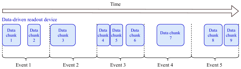
In this situation, the [Metronome] module can be used to slice the data stream into regular time frames with a defined length, as indicated in Figure 1.
In addition to splitting the data stream into frames, trigger numbers can be added to each of the frames as described in the module documentation of the [Metronome] in Section LABEL:metronome. This can be used to process data exclusively recorded with triggered devices, where no timing information is available or necessary from any of the devices involved. The module should then be set up to always add one trigger to each of its events, and all subsequent detectors will simply compare to this trigger number and add their event data.
If used, the [Metronome] module always has to be placed as first module in the data analysis chain because it will attempt to define the event and to add it to the clipboard. This operation fails if an event has already been defined by a previous module.
5.4 Example Configurations for Event Building
In these examples, it is assumed that all data have been recorded using the EUDAQ2 framework, and that the [EventLoaderEUDAQ2] is used for all devices to read and decode their data. However, this example pattern is not limited to that case and a very similar configuration could be used when the device data have been stored into device-specific native data files.
5.4.1 Event Definition by Frame-Based DUT

This example demonstrates the setup for event building based on a frame-based DUT. The event building strategy for this situation is sketched in Figure 2. The configuration contains four different devices:
- CLICpix2 [17]:
-
This prototype acts as device under test and is a detector designed for operation at a linear collider, implementing a frame-based readout scheme. In this example, it will define the event.
- TLU [20]:
-
The trigger logic unit records scintillator coincidence signals with their respective timestamps, generates trigger signals and provides the reference clock for all other devices.
- Timepix3 [19]:
-
This detector is operated in its data-driven mode, where the external clock from the TLU is used to timestamp each individual pixel hit. The hits are directly read out and sent to the data acquisition system in a continuous data stream.
- MIMOSA26 [21]:
-
These detectors are devices with a continuous rolling shutter readout, which do not record any timing information in the individual frames. The data are tagged with the incoming trigger IDs by its DAQ system.
In order to build proper events from these devices, the following configuration is used:
The first module will define the event using the frame start and end timestamps from the CLICpix2 device. Then, the data from the TLU are added by comparing the trigger timestamps to the event. The matching trigger numbers are added to the event for later use. Subsequently, the Timepix3 device adds its data to the event by comparing the individual pixel timestamps to the existing event definition. Finally, the six MIMOSA26 detectors are added one-by-one via the automatic type-instantiation of detector modules described in Section 3.4.3. Here, the trigger numbers from the detector data are compared to the ones stored in the event as described in Section 5.2.3.
It should be noted that in this example, the data from the TLU and the six MIMOSA26 planes are read from the same file. The event building algorithm is transparent to how the individual detector data are stored, and the very same building pattern could be used when storing the data in separate files. In addition, it should be noted that swapping the order of the Timepix3 and MIMOSA26 detectors is also a valid configuration with identical results to the above scheme.
5.4.2 Event Definition by Trigger Logic Unit
This example demonstrates the setup for event building based on the trigger logic unit. The configuration contains the same devices as the example in Section 5.4.1 but replaces the CLICpix2 by the ATLASpix:
- ATLASpix [22]:
-
This prototype acts as device under test and is a detector initially designed for the ATLAS ITk upgrade, implementing a triggerless column-drain readout scheme.
In order to build proper events from these devices, the following configuration is used:
The first module will define the event using the frame start and end timestamps from the TLU device. As in the previous example, the MIMOSA26 data will be added based on the trigger number. The frame start provided by the TLU corresponds to the trigger timestamp and the frame end is one clockcycle later. However, due to the rolling shutter readout scheme, the hits that are read out from the MIMOSA26 planes when receiving a trigger may have happened in a time period before or after the trigger signal. Consequently, the event times need to be corrected using the adjust_event_times parameter (described in Section LABEL:eventloadereudaq2) such that the data from the ATLASpix and Timepix3 can be added to the event in the entire time window in which the MIMOSA26 hits may have occurred.
It should be noted that swapping the order of the Timepix3, ATLASpix, and MIMOSA26 detectors is also a valid configuration with identical results to the above scheme.
6 Using Corryvreckan as Online Monitor
Reconstructing test beam data with Corryvreckan does not require many dependencies and is usually very fast due to its efficient data handling and fast reconstruction routines. It is therefore possible to directly perform a full reconstruction including tracking and analysis of the DUT data during data taking. On Linux machines, this is even possible on the data currently recorded since multiple read pointers are allowed per file.
The Corryvreckan framework comes with an online monitoring tool in form of a module for data quality monitoring and immediate feedback to the shifter. The [OnlineMonitor] is a relatively simple graphical user interface that displays and updates histograms and graphs produced by other modules during the run. It should therefore be placed at the very end of the analysis chain in order to have access to all histograms previously registered by other modules.
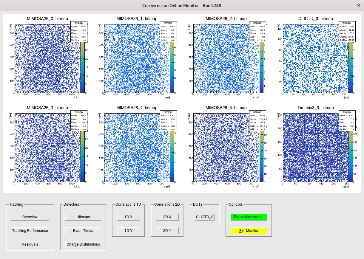
A screenshot of the interface is displayed in Figure 3, showing histograms from the reconstruction of data recorded with the setup presented in Section 5.4.1. The histograms are distributed over several canvases according to their stage of production in the reconstruction chain. It is possible to display histograms for all registered detectors through the %DETECTOR% keyword in the configuration. Histograms only from all detectors marked as DUT can be added by placing %DUT% in the histogram path.
The module has a default configuration that should match many reconstruction configurations, but each of the canvases and histograms can be freely configured as described in the documentation of the [OnlineMonitor] in Section LABEL:onlinemonitor.
7 Alignment Procedure
As decribed in Section 4.3, an analysis with Corryvreckan requires a configuration file defining which detectors are present in the setup.
This file also contains the position and rotation of each detector plane.
The Z-positions of all planes can and must be measured by hand in the existing test beam setup and entered in this configuration file for the analysis.
The X- and Y-positions as well as the rotations cannot be measured precisely by hand.
However, these have a strong influence on the tracking since a misalignment of a fraction of a millimeter might already correspond to a shift by multiple pixel pitches.
Consequently, an alignment procedure is needed in which the detector planes are shifted and rotated iteratively relative to the detector with role=reference to increase the tracking quality.
More technically, the track residuals on all planes, i.e. the distribution of the spatial distance between the interpolated track intercept and the associated cluster on the plane need to be centered around zero and ’as narrow as possible’ – the width of the distribution depends on the tracking resolution of the telescope and is influenced by many factors such as the beam energy, the material budget of the detector planes, the distance between the detector planes, etc.
It is important to correctly set the spatial_resolution specified in the detector configuration file described in Section 4.3 because is defining the uncertainty on the cluster positions and therefore influences the track .
This chapter provides a description of how to use the alignment features of Corryvreckan.
It also includes step-by-step instructions on how to align the detector planes for new set of test beam data.
Example configuration files can be found in the testing/ directory of the repository.
These are based on a Timepix3 [19] telescope with an ATLASpix [22] DUT at the CERN SPS with a pion beam of .
For the alignment of the reference telescope and device-under-test (DUT), the following modules are available in Corryvreckan.
-
•
[Prealignment] for both telescope and DUT prealignment (see Section LABEL:prealignment).
-
•
[AlignmentTrackChi2] used for telescope alignment (see Section LABEL:alignmenttrackchi2) and is relatively robust against an initial misalignment but usually needs several iterations.
-
•
[AlignmentMillepede], an alternative telescope alignment algorithm (see Section LABEL:alignmentmillepede) which requires fewer iterations to reach a precise alignment but needs a better prealignment.
-
•
[AlignmentDUTResidual] used for DUT alignment (see Section LABEL:alignmentdutresidual).
The general procedure that needs to be followed for a successful alignment is outlined here and explained in detail below.
-
1.
Prealignment of the telescope (ignoring the DUT).
-
2.
Alignment of the telescope (ignoring the DUT).
-
3.
Prealignment of the DUT (telescope geometry is frozen).
-
4.
Alignment of the DUT (telescope alignment is frozen).
When using the alignment modules, the new geometry is written out to a new geometry file which needs to be specified using the parameter detectors_file_updated. For details, see Section 3.3.
Correlation vs. Residual
A spatial correlation plot is filled with the spatial difference of any cluster on a given detector plane minus the position of any cluster on the reference plane. No tracking is required to fill these histograms.
A spatial residual plot shows the difference of the interpolated track intercept onto a given plane minus the position of its associated cluster.
Consequently, the goal of the alignment is to force the residuals to be centered around zero. The correlations do not necessarily have to be centered at zero as a possible offset reflects the physical displacement of a detector plane in X and Y with respect to the reference plane. However, it can be useful to inspect the correlation plots especially in the beginning when the alignment is not yet good enough for a reasonable tracking.
7.1 Aligning the Telescope
Initially, the telescope needs to be aligned. For this, the DUT is ignored.
Prealignment of the Telescope
The [AlignmentTrackChi2] module requires a careful prealignment. Otherwise it does not converge and the alignment will fail. The Z-positions of all planes need to be measured by hand in the existing test beam setup and then adjusted in the detectors file. For X and Y, the alignment file from an already aligned run with the same telescope plane arrangement is a solid basis to start from. If no previous alignment is available, all values for X and Y should be set to 0.
For the prealignment, two strategies can be applied:
-
•
The [Prealignment] module can be used (see Section LABEL:prealignment).
-
•
If the above does not bring the expected result, a manual prealignment can be performed as described below.
To have a first look at the initial alignment guess, one can run
$ /path/to/corryvreckan/bin/corry                     \
    -c analyse_telescope.conf                         \
   [-o detectors_file=<detectorsFile>                 \
    -o histogram_file=<histogramFile>                 \
    -o EventLoaderTimepix3.input_directory=<inputDir>]
The spatial_cut_abs/rel in [Tracking4D] should be set to multiple () pixel pitch.
One can inspect the spatial correlations in X and Ythe track , and the residuals with the online monitoring or by opening the generated ROOT file after finishing the script.
These can be found in the modules [Correlations] (see Section LABEL:correlations) and [Tracking4D] (see Section LABEL:tracking4d).
To save time, one can limit the number of processed tracks. For instance, set number_of_events=10000 or number_of_tracks=10000 (see Section 3.3).
If no peak at all is apparent in the correlations or residuals, the hitmaps can be checked to see if valid data is actually available for all planes.
Now, the [Prealignment] module can be used. To prealign only the telescope, the DUT can be excluded by using type=<detector_type_of_telescope> (e.g. CLICPIX2). For details, see Section 3.4.
To use the module, align_tel.conf needs to be edited such that [Prealignment] is enabled and [Alignment] is disabled:
Then one can run
$ /path/to/corryvreckan/bin/corry                      \
    -c align_telescope.conf                            \
   [-o detectors_file=<detectorsFile>                  \
    -o detectors_file_updated=<detectorsFileUpdated>   \
    -o histogram_file=<histogramFile>                  \
    -o EventLoaderTimepix3.input_directory=<inputDir>]
The actual prealignment is only performed after the events have been analyzed and written to the detectors file in the finalizing step. This means to check whether the alignment has improved, one needs to re-run the analysis or the next iteration of the alignment as the previously generated ROOT file corresponds to the initial alignment. This is the case for every iteration of the prealignment or alignment.
Generally, it suffices to run the [Prealignment] module once and then proceed with the next step.
Manual Prealignment of the Telescope
If the prealignment using the module [Prealignment] does not bring the expected results, one can also perform the same steps manually by investigating the residuals of the DUT with respect to tracks. For the residuals, the shift of the peak from 0 can be estimated with a precision of by zooming in using the TBrowser. For instance, if the peak is shifted by +, the detectors file needs to be edited and should be added to the respective position, if , subtracted.
After modifying the positions of individual planes in the configuration file, Corryvreckan can be re-run to check the correlation and residual plots for the updated geometry. These steps need to be iterated a few times until the peaks of the residuals are centered around 0.
Rotational misalignments can be inferred from the slope of the 2D spatial correlation plots, the actual rotation angle has to be calculated using the respective pixel pitches of the devices.
It is important not to force the peak of the spatial correlations to be at exactly 0 because the position of the peak corresponds to the physical displacement of a detector plane in X and Y with respect to the reference plane. The spatial correlations should only be used if the spatial residual plots are not filled reasonable due to bad tracking. Hence, the spatial correlations can be shifted towards zero in a first iteration.
Alignment of the Telescope
After the prealignment, the actual precise alignment can be performed using the [AlignmentTrackChi2] module (see Section LABEL:alignmenttrackchi2). To this end, align_tel.conf needs to be modified such that the prealignment is disabled and the alignment is enabled:
The algorithm performs an optimisation of the track . Typically, the alignment needs to be iterated a handful of times until the residuals (which again can be inspected in the ROOT file after re-running the analysis) are nicely centered around 0 and ’as narrow as possible’ – the RMS of the residuals corresponds to the spatial resolution of each plane (convolved with the resolution of the telescope) and should thus be pixel pitch. Starting with a spatial_cut_abs/rel in [Tracking4D] (see Section LABEL:tracking4d) of multiple () pixel pitches, it should be decreased incrementally down to the pixel pitch (e.g. run twice, then run twice, then twice, and then twice). This allows to perform the alignment with a tight selection of very high quality tracks only. Also the max_track_chi2ndof should be decreased for the same reason. For the further analysis, the cuts can be released again.
It may happen that the procedure runs into a ’false minimum’, i.e. it converges in a wrong alignment in which the residuals are clearly not centered around 0. In this case, it is required to go one step back and improve the prealignment.
Once the alignment is done, one should obtain narrow residuals centered around 0 and a good distribution of the track as shown in Figures 4. If the alignment keeps to fail, it is possible to allow only for rotational or translational alignment while freezing the other for one or a few iterations.
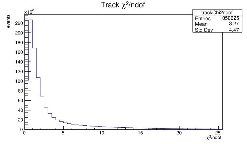
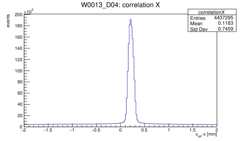
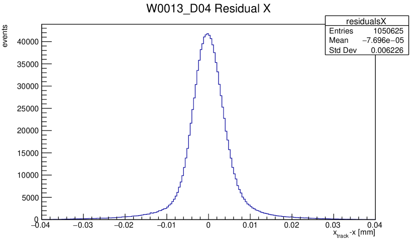
Instead of using [AlignmentTrackChi2], one can also use the module [AlignmentMillepede] (see Section LABEL:alignmentmillepede). It allows a simultaneous fit of both the tracks and the alignment constants. The modules stops if the convergence, i.e. the absolute sum of all corrections over the total number of parameters, is smaller than the configured value, and the aligment is complete. It should be noted that this module requires a rather good prealignment already.
7.2 Aligning the DUT
Once the telescope is aligned, its geometry is not changed anymore. From now on, it is used to build tracks which are then matched to clusters on the DUT.
Prealignment of the DUT
The prealignment of the DUT follows the same strategy as for the telescope. To look at the current alignment, the script
$ /path/to/corryvreckan/bin/corry                          \
    -c analyse_atlaspix.conf                               \
   [-o detectors_file=<detectorsFile>                      \
    -o histogram_file=<histogramFile>                      \
    -o EventLoaderTimepix3.input_directory=<inputDir_TPX>  \
    -o EventLoaderATLASpix.input_directory=<inputDir_APX>]
needs to be run. If no better guess is available, the initial alignment of the DUT should be set to .
Then, by repeatedly running Corryvreckan and modifying the position of the DUT in the detectors file one should be able to bring the peaks of the spatial residuals in X and Y close to zero. If no peak at all can be seen in the residual plots, the spatial correlations plots can be inspected. In addition, potentially parameters related to the corresponding event loader need to be corrected in the configuration file.
If using the [Prealignment] module, it is possible to prealign all planes at once as described above in Section 7.1. If only the DUT shall be prealigned here, the parameter name=<name_of_dut> or type=<detector_type_of_dut> need to be used. Otherwise, the telescope planes are also shifted again destroying the telescope alignment.
Alignment of the DUT
The alignment strategy for the DUT is similar as for the telescope and requires multiple iterations. In align_dut.conf, the prealignment needs to be disabled and the alignment enabled. Now, the algorithm optimizes the residuals of the tracks through the DUT.
Then run
$ /path/to/corryvreckan/bin/corry                          \
    -c align_dut.conf                                      \
   [-o detectors_file=<detectorsFile>                      \
    -o detectors_file_updated=<detectorsFileUpdated>       \
    -o histogram_file=<histogramFile>                      \
    -o EventLoaderTimepix3.input_directory=<inputDir_TPX>  \
    -o EventLoaderATLASpix.input_directory=<inputDir_APX>]
Like for the telescope alignment, the RMS of the residuals can be interpreted as the spatial resolution of the DUT (convolved with the track resolution of the telescope at the position if the DUT) and should thus be pixel pitch. Again, starting with a spatial_cut_abs/rel in [DUTAssociation] (see Section LABEL:dutassociation) of multiple () pixel pitches, it should be decreased incrementally down to the pixel pitch. Note that an asymmetric pixel geometry requires the spatial_cut_abs/rel to be chosen accordingly.
If the alignment keeps to fail, it is possible to allow only for rotational or translational alignment while freezing the other for one or a few iterations.
8 Modules
This chapter describes the currently available Corryvreckan modules in detail. It comprises a description of the implemented modules as well as possible configuration parameters along with their defaults. Furthermore, an overview of output plots is provided. For inquiries about certain modules or their documentation, the Corryvreckan issue tracker which can be found in the repository [6] should be used as described in Section 1.4. The modules are listed in alphabetical order. \foreach\nin modules/AlignmentDUTResidual.tex,modules/AlignmentMillepede.tex,modules/AlignmentTrackChi2.tex,modules/AnalysisDUT.tex,modules/AnalysisEfficiency.tex,modules/AnalysisTelescope.tex,modules/AnalysisTimingATLASpix.tex,modules/Clustering4D.tex,modules/ClusteringSpatial.tex,modules/Correlations.tex,modules/DUTAssociation.tex,modules/EtaCalculation.tex,modules/EtaCorrection.tex,modules/EventLoaderATLASpix.tex,modules/EventLoaderCLICpix.tex,modules/EventLoaderCLICpix2.tex,modules/EventLoaderEUDAQ.tex,modules/EventLoaderEUDAQ2.tex,modules/EventLoaderMuPixTelescope.tex,modules/EventLoaderTimepix1.tex,modules/EventLoaderTimepix3.tex,modules/FileReader.tex,modules/FileWriter.tex,modules/ImproveReferenceTimestamp.tex,modules/MaskCreator.tex,modules/MaskCreatorTimepix3.tex,modules/Metronome.tex,modules/OnlineMonitor.tex,modules/Prealignment.tex,modules/TextWriter.tex,modules/Tracking4D.tex,modules/TrackingSpatial.tex,modules/TreeWriterDUT.tex
9 Extending the Corryvreckan Framework
This chapter provides some initial information for developers planning on extending the Corryvreckan framework. Corryvreckan is a community project that benefits from active participation in the development and code contributions from users. Users are encouraged to discuss their needs via the issue tracker of the repository [6] to receive ideas and guidance on how to implement a specific feature. Getting in touch with other developers early in the development cycle avoids spending time on features which already exist or are currently under development by other users.
The repository contains a few tools to facilitate contributions and to ensure code quality as detailed in Chapter 10.
9.1 Writing Additional Modules
Given the modular structure of the framework, its functionality can be easily extended by adding a new module. To facilitate the creation of new modules including their CMake files and initial documentation, the script addModule.sh is provided in the etc/ directory of the repository. It will ask for a name and type of the module as described in Section 3.4 and create all code necessary to compile a first (and empty) version of the files.
The content of each of the files is described in detail in the following paragraphs.
9.1.1 Files of a Module
Every module directory should at minimum contain the following documents (with <ModuleName> replaced by the name of the module):
-
•
CMakeLists.txt: The build script to load the dependencies and define the source files of the library.
-
•
README.md: Full documentation of the module.
-
•
<ModuleName>.h: The header file of the module.
-
•
<ModuleName>.cpp: The implementation file of the module.
These files are discussed in more detail below. By default, all modules added to the src/modules/ directory will be built automatically by CMake. If a module depends on additional packages which not every user may have installed, one can consider adding the following line to the top of the module’s CMakeLists.txt:
CMakeLists.txt
Contains the build description of the module with the following components:
-
1.
On the first line either CORRYVRECKAN_DETECTOR_MODULE(MODULE_NAME), CORRYVRECKAN_DUT_MODULE(MODULE_NAME) or CORRYVRECKAN_GLOBAL_MODULE(MODULE_NAME) depending on the type of module defined. The internal name of the module is automatically saved in the variable ${MODULE_NAME} which should be used as an argument to other functions. Another name can be used by overwriting the variable content, but in the examples below, ${MODULE_NAME} is used exclusively and is the preferred method of implementation. For DUT and Detector modules, the type of detector this module is capable of handling can be specified by adding so-called type restrictions, e.g.
The module will then only be instantiated for detectors of one of the given types. This is particularly useful for event loader modules which read a very specific file format.
-
2.
The following lines should contain the logic to load possible dependencies of the module (below is an example to load Geant4). Only ROOT is automatically included and linked to the module.
-
3.
A line with CORRYVRECKAN_MODULE_SOURCES(${MODULE_NAME} sources) defines the module source files. Here, sources should be replaced by a list of all source files relevant to this module.
-
4.
Possible lines to include additional directories and to link libraries for dependencies loaded earlier.
-
5.
A line containing CORRYVRECKAN_MODULE_INSTALL(${MODULE_NAME}) to set up the required target for the module to be installed to.
A simple CMakeLists.txt for a module named Test which should run only on DUT detectors of type Timepix3 is provided below as an example.
README.md
The README.md serves as the documentation for the module and should be written in Markdown format [28]. It is automatically converted to LaTeX using Pandoc [29] and included in the user manual in Chapter 8. By documenting the module functionality in Markdown, the information is also viewable with a web browser in the repository within the module sub-folder.
The README.md should follow the structure indicated in the README.md file of the Dummy module in src/modules/Dummy, and should contain at least the following sections:
-
•
The H1-size header with the name of the module and at least the following required elements: the Maintainer, the Module Type and the Status of the module. The module type should be either GLOBAL, DETECTOR, DUT. If the module is working and well-tested, the status of the module should be Functional. By default, new modules are given the status Immature. The maintainer should mention the full name of the module maintainer, with their email address in parentheses. A minimal header is therefore:
# ModuleName
Maintainer: Example Author (<example@example.org>)
Module Type: GLOBAL
Status: Functional
In addition, the Detector Type should be mentioned for modules of types DETECTOR and DUT.
-
•
An H3-size section named Description, containing a short description of the module.
-
•
An H3-size section named Parameters, with all available configuration parameters of the module. The parameters should be briefly explained in an itemised list with the name of the parameter set as an inline code block.
-
•
An H3-size section named Plots Created, listing all plots created by this module.
-
•
An H3-size section with the title Usage which should contain at least one simple example of a valid configuration for the module.
ModuleName.h and ModuleName.cpp
All modules should consist of both a header file and a source file. In the header file, the module is defined together with all of its methods. Doxygen documentation should be added to explain what each method does. The source file should provide the implementation of every method. Methods should only be declared in the header and defined in the source file in order to keep the interface clean.
9.1.2 Module structure
All modules must inherit from the Module base class, which can be found in src/core/module/Module.hpp. The module base class provides two base constructors, a few convenient methods and several methods which the user is required to override. Each module should provide a constructor using the fixed set of arguments defined by the framework; this particular constructor is always called during by the module instantiation logic. These arguments for the constructor differ for global and detector/DUT modules.
For global modules, the constructor for a [TestModule] should be:
For detector and DUT modules, the first argument are the same, but the last argument is a std::shared_ptr to the linked detector. It should always forward this detector to the base class together with the configuration object. Thus, the constructor of a detector module is:
In addition to the constructor, each module can override the following methods:
-
•
initialise(): Called after loading and constructing all modules and before starting the analysis loop. This method can for example be used to initialize histograms.
-
•
run(std::shared_ptr<Clipboard>clipboard): Called for every time frame or triggered event to be analyzed. The argument represents a pointer to the clipboard where the event data is stored. A status code is returned to signal the framework whether to continue processing data or to end the run.
-
•
finalise(): Called after processing all events in the run and before destructing the module. Typically used to summarize statistics like the number of tracks used in the analysis or analysis results like the chip efficiency. Any exceptions should be thrown from here instead of the destructor.
10 Development Tools & Continuous Integration
The following chapter will introduce a few tools included in the framework to ease development and help to maintain a high code quality. This comprises tools for the developer to be used while coding, as well as a continuous integration (CI) and automated test cases of various framework and module functionalities.
10.1 Additional Targets
A set of testing targets in addition to the standard compilation targets are automatically created by CMake to enable additional code quality checks and testing. Some of these targets are used by the project’s CI, others are intended for manual checks. Currently, the following targets are provided:
- makeformat
-
invokes the clang-format tool to apply the project’s coding style convention to all files of the code base. The format is defined in the .clang-format file in the root directory of the repository and mostly follows the suggestions defined by the standard LLVM style with minor modifications. Most notably are the consistent usage of four whitespace characters as indentation and the column limit of 125 characters. This can be further simplified by installing the git hook provided in the directory /etc/git-hooks/. A hook is a script called by git before a certain action. In this case, it is a pre-commit hook which automatically runs clang-format in the background and offers to update the formatting of the code to be committed. It can be installed by calling
once.
- makecheck-format
-
also invokes the clang-format tool but does not apply the required changes to the code. Instead, it returns an exit code 0 (pass) if no changes are necessary and exit code 1 (fail) if changes are to be applied. This is used by the CI.
- makelint
-
invokes the clang-tidy tool to provide additional linting of the source code. The tool tries to detect possible errors (and thus potential bugs), dangerous constructs (such as uninitialized variables) as well as stylistic errors. In addition, it ensures proper usage of modern C++ standards. The configuration used for the clang-tidy command can be found in the .clang-tidy file in the root directory of the repository.
- makecheck-lint
-
also invokes the clang-tidy tool but does not report the issues found while parsing the code. Instead, it returns an exit code 0 (pass) if no errors have been produced and exit code 1 (fail) if issues are present. This is used by the CI.
- makecppcheck
-
runs the cppcheck command for additional static code analysis. The output is stored in the file cppcheck_results.xml in XML2.0 format. It should be noted that some of the issues reported by the tool are to be considered false positives.
- makecppcheck-html
-
compiles a HTML report from the defects list gathered by makecppcheck. This target is only available if the cppcheck-htmlreport executable is found in the PATH.
- makepackage
-
creates a binary release tarball as described in Section 10.2.
10.2 Packaging
Corryvreckan comes with a basic configuration to generate tarballs from the compiled binaries using the CPack command. In order to generate a working tarball from the current Corryvreckan build, the RPATH of the executable should not be set, otherwise the corry binary will not be able to locate the dynamic libraries. If not set, the global LD_LIBRARY_PATH is used to search for the required libraries:
$ mkdir build
$ cd build
$ cmake -DCMAKE_SKIP_RPATH=ON ..
$ make package
The content of the produced tarball can be extracted to any location of the file system, but requires the ROOT6 and Geant4 libraries as well as possibly additional libraries linked by individual at runtime.
For this purpose, a setup.sh shell script is automatically generated and added to the tarball. By default, it contains the ROOT6 path used for the compilation of the binaries. Additional dependencies, either library paths or shell scripts to be sourced, can be added via CMake for individual modules using the CMake functions described below. The paths stored correspond to the dependencies used at compile time, it might be necessary to change them manually when deploying on a different computer.
ADD_RUNTIME_DEP(name)
This CMake command can be used to add a shell script to be sourced to the setup file. The mandatory argument name can either be an absolute path to the corresponding file, or only the file name when located in a search path known to CMake, for example:
The command uses the GET_FILENAME_COMPONENT command of CMake with the PROGRAM option. Duplicates are removed from the list automatically. Each file found will be written to the setup file as
source <absolute path to the file>
ADD_RUNTIME_LIB(names)
This CMake command can be used to add additional libraries to the global search path. The mandatory argument names should be the absolute path of a library or a list of paths, such as:
The command uses the GET_FILENAME_COMPONENT command of CMake with the DIRECTORY option to determine the directory of the corresponding shared library. Duplicates are removed from the list automatically. Each directory found will be added to the global library search path by adding the following line to the setup file:
export LD_LIBRARY_PATH="<library directory>:$LD_LIBRARY_PATH"
10.3 Continuous Integration
Quality and compatibility of the Corryvreckan framework is ensured by an elaborate continuous integration (CI) which builds and tests the software on all supported platforms. The Corryvreckan CI uses the GitLab Continuous Integration features and consists of six distinct stages. It is configured via the .gitlab-ci.yml file in the repository’s root directory, while additional setup scripts for the GitLab CI Runner machines and the Docker instances can be found in the .gitlab-ci.d directory.
The compilation stage builds the framework from the source on different platforms. Currently, builds are performed on Scientific Linux 6, CentOS7, and Mac OS X. On Linux type platforms, the framework is compiled with recent versions of GCC and Clang, while the latest AppleClang is used on Mac OS X. The build is always performed with the default compiler flags enabled for the project:
    -pedantic -Wall -Wextra -Wcast-align -Wcast-qual -Wconversion
    -Wuseless-cast -Wctor-dtor-privacy -Wzero-as-null-pointer-constant
    -Wdisabled-optimization -Wformat=2 -Winit-self -Wlogical-op
    -Wmissing-declarations -Wmissing-include-dirs -Wnoexcept
    -Wold-style-cast -Woverloaded-virtual -Wredundant-decls
    -Wsign-conversion -Wsign-promo -Wstrict-null-sentinel
    -Wstrict-overflow=5 -Wswitch-default -Wundef -Werror -Wshadow
    -Wformat-security -Wdeprecated -fdiagnostics-color=auto
    -Wheader-hygiene
The testing stage executes the framework tests described in Section 10.5. All tests are expected to pass, and no code that fails to satisfy all tests will be merged into the repository.
The formatting stage ensures proper formatting of the source code using the clang-format and following the coding conventions defined in the .clang-format file in the repository. In addition, the clang-tidy tool is used for “linting” of the source code. This means, the source code undergoes a static code analysis in order to identify possible sources of bugs by flagging suspicious and non-portable constructs used. Tests are marked as failed if either of the CMake targets makecheck-format or makecheck-lint fail. No code that fails to satisfy the coding conventions and formatting tests will be merged into the repository.
The documentation stage prepares this user manual as well as the Doxygen source code documentation for publication. This also allows to identify e.g. failing compilation of the LaTeX documents or additional files which accidentally have not been committed to the repository.
The packaging stage wraps the compiled binaries up into distributable tarballs for several platforms. This includes adding all libraries and executables to the tarball as well as preparing the setup.sh script to prepare run-time dependencies using the information provided to the build system. This procedure is described in more detail in Section 10.2.
Finally, the deployment stage is only executed for new tags in the repository. Whenever a tag is pushed, this stages receives the build artifacts of previous stages and publishes them to the Corryvreckan project website through the EOS file system [30]. More detailed information on deployments is provided in the following.
10.4 Automatic Deployment
The CI is configured to automatically deploy new versions of Corryvreckan and its user manual and code reference to different places to make them available to users. This section briefly describes the different deployment end-points currently configured and in use. The individual targets are triggered either by automatic nightly builds or by publishing new tags. In order to prevent accidental publications, the creation of tags is protected. Only users with Maintainer privileges can push new tags to the repository. For new tagged versions, all deployment targets are executed.
10.4.1 Software deployment to CVMFS
The software is automatically deployed to CERN’s VM file system (CVMFS) [7] for every new tag. In addition, the master branch is built and deployed every night. New versions are published to the folder /cvmfs/clicdp.cern.ch/software/corryvreckan/ where a new folder is created for every new tag, while updates via the master branch are always stored in the latest folder.
The deployed version currently comprises of all modules as well as the detector models shipped with the framework. An additional setup.sh is placed in the root folder of the respective release, which allows all the runtime dependencies necessary for executing this version to be set up. Versions for both SLC 6 and CentOS 7 are provided.
The deployment CI job runs on a dedicated computer with a GitLab SSH runner. Job artifacts from the packaging stage of the CI are downloaded via their ID using the script found in .gitlab-ci.d/download_artifacts.py, and are made available to the cvclicdp user who has access to the CVMFS interface. The job checks for concurrent deployments to CVMFS and then unpacks the tarball releases and publishes them to the CLICdp experiment CVMFS space, the corresponding script for the deployment can be found in .gitlab-ci.d/gitlab_deployment.sh. This job requires a private API token to be set as secret project variable through the GitLab interface, currently this token belongs to the service account user corry.
10.4.2 Documentation deployment to EOS
The project documentation is deployed to the project’s EOS space at /eos/project/c/corryvreckan/www/ for publication on the project website. This comprises both the PDF and HTML versions of the user manual (subdirectory usermanual) as well as the Doxygen code reference (subdirectory reference/). The documentation is only published only for new tagged versions of the framework.
The CI jobs uses the ci-web-deployer Docker image from the CERN GitLab CI tools to access EOS, which requires a specific file structure of the artifact. All files in the artifact’s public/ folder will be published to the www/ folder of the given project. This job requires the secret project variables EOS_ACCOUNT_USERNAME and EOS_ACCOUNT_PASSWORD to be set via the GitLab web interface. Currently, this uses the credentials of the service account user corry.
10.4.3 Release tarball deployment to EOS
Binary release tarballs are deployed to EOS to serve as downloads from the website to the directory /eos/project/c/corryvreckan/www/releases. New tarballs are produced for every tag as well as for nightly builds of the master branch, which are deployed with the name corryvreckan-latest-<system-tag>-opt.tar.gz.
The files are taken from the packaging jobs and published via the ci-web-deployer Docker image from the CERN GitLab CI tools. This job requires the secret project variables EOS_ACCOUNT_USERNAME and EOS_ACCOUNT_PASSWORD to be set via the GitLab web interface. Currently, this uses the credentials of the service account user corry.
10.4.4 Building Docker images
New Corryvreckan Docker images are automatically created and deployed by the CI for every new tag and as a nightly build from the master branch. New versions are published to project Docker container registry [8]. Tagged versions can be found via their respective tag name, while updates via the nightly build are always stored with the latest tag attached.
The final Docker image is formed from three consecutive images with different layers of software added. The ‘base‘ image contains all build dependencies such as compilers, CMake, and git. It derives from a CentOS7 Docker image and can be build using the etc/docker/Dockerfile.base file via the following commands:
# Log into the CERN GitLab Docker registry:
$ docker login gitlab-registry.cern.ch
# Compile the new image version:
$ docker build --file etc/docker/Dockerfile.base          \
               --tag gitlab-registry.cern.ch/corryvreckan/\
                     corryvreckan/corryvreckan-base       \
               .
# Upload the image to the registry:
$ docker push gitlab-registry.cern.ch/corryvreckan/\
              corryvreckan/corryvreckan-base
The main dependency of the framework us ROOT6, which is added to the base image via the deps Docker image created from the file etc/docker/Dockerfile.deps via:
$ docker build --file etc/docker/Dockerfile.deps          \
               --tag gitlab-registry.cern.ch/corryvreckan/\
               corryvreckan/corryvreckan-deps             \
              .
$ docker push gitlab-registry.cern.ch/corryvreckan/\
              corryvreckan/corryvreckan-deps
These images are created manually and only updated when necessary, i.e. if major new version of the underlying dependencies are available.
Finally, the latest revision of Corryvreckan is built using the file etc/docker/Dockerfile. This job is performed automatically by the continuous integration and the created containers are directly uploaded to the project’s Docker registry.
$ docker build --file etc/docker/Dockerfile                            \
               --tag gitlab-registry.cern.ch/corryvreckan/corryvreckan \
              .
A short summary of potential use cases for Docker images is provided in Section 2.3.
10.5 Data-driven Functionality Tests
The build system of the framework provides a set of automated tests which are executed by the CI to ensure proper functioning of the framework and its modules. The tests can also be manually invoked from the build directory of Corryvreckan with
$ ctest
Individual tests be executed or ignored using the -E (exclude) and -R (run) switches of the ctest program:
$ ctest -R test_timepix3tel
The configurations of the tests can be found in the testing/ directory of the repository and are automatically discovered by CMake. CMake automatically searches for Corryvreckan configuration files in the respective directory and passes them to the Corryvreckan executable (cf. Section 3.1).
Adding a new test requires placing the configuration file in the directory, specifying the pass or fail conditions based on the tags described in the following paragraph, and providing reference data as described below.
Pass and Fail Conditions
The output of any test is compared to a search string in order to determine whether it passed or failed. These expressions are simply placed in the configuration file of the corresponding tests, a tag at the beginning of the line indicates whether it should be used for passing or failing the test. Each test can only contain one passing and one failing expression. If different functionality and thus outputs need to be tested, a second test should be added to cover the corresponding expression.
- Passing a test
-
The expression marked with the tag #PASS has to be found in the output in order for the test to pass. If the expression is not found, the test fails.
- Failing a test
-
If the expression tagged with #FAIL is found in the output, the test fails. If the expression is not found, the test passes.
- Depending on another test
-
The tag #DEPENDS can be used to indicate dependencies between tests, e.g. if a test requires a data file produced by another test.
- Defining a timeout
-
For performance tests the runtime of the application is monitored, and the test fails if it exceeds the number of seconds defined using the #TIMEOUT tag.
- Adding additional CLI options
-
Additional module command line options can be specified for the corry executable using the #OPTION tag, following the format found in Section 3.1. Multiple options can be supplied by repeating the #OPTION tag in the configuration file, only one option per tag is allowed.
- Providing datasets
-
The #DATASET tag allows to specify a configured data set which has to be available in order for the test to be executed. Datasets and their configuration is described below. Only one data set per tag is allowed, multiple tags can be used.
Providing Reference Datasets
Reference datasets for testing are centrally stored on EOS at /eos/project/c/corryvreckan/www/data/ and are accessible over the internet. The download_data.py tool provided in the testing/ directory of the framework is capable of downloading individual data files, checking their integrity via an SHA256 hash and decompressing the tar archives.
Each test can specify one or several data sets it requires to be present in order to successfully run via the #DATASET tag in the configuration file. The datasets have to be made known to the download script together with their calculated SHA256 hashes when adding a new test to the repository. The file name and hash have to be added to the Python DATASETS array, and the file of the dataset has to be uploaded manually to EOS by one of the framework maintainers. The SHA256 hash can be generated by executing:
openssl sha256 <dataset>
Paths in the test configuration files should be provided relative to the testing/ directory, all downloaded data will be stored in individual subdirectories per dataset following the naming scheme testing/data/<dataset>.
11 Additional Tools & Resources
The following section briefly describes tools provided with the Corryvreckan framework.
11.1 Jobsub
11.1.1 Overview
jobsub is a tool for the convenient run-specific modification of Corryvreckan configuration files and their execution through the corry executable. It can be used for automated processing of several data files and/or scans of reconstruction parameters. It is derived from the original jobsub written for EUTelescope [31] by Hanno Perrey, Lund University.
It should be noted that when using jobsub on a local machine, the jobs are processed one by one. When running in batch mode, all jobs are submitted to HTCondor and processed in parallel.
11.1.2 Usage
The following help text is printed when invoking jobsub with the -h argument:
usage: jobsub.py [-h] [--option NAME=VALUE] [-c FILE] [-csv FILE]
                 [--log-file FILE] [-l LEVEL] [-s] [--dry-run]
         [--batch FILE] [--subdir]
                 jobtask [runs [runs ...]]

A tool for the convenient run-specific modification of Corryvreckan
steering files and their execution through the corry executable

positional arguments:
  runs                  The runs to be analyzed; can be a list of
                        single runs and/or a range, e.g. 1056-1060.

optional arguments:
  -h, --help            show this help message and exit
  --version             show program’s version number and exit
  -c FILE, --conf-file FILE, --config FILE
                        Configuration file with all Corryvreckan
                        algorithms defined
  --option NAME=VALUE, -o NAME=VALUE
                        Specify further options such as
                        ’beamenergy=5.3’. This switch be specified
                        several times for multiple options
                        or can parse a comma-separated list of options.
                        This switch overrides any configuration file
                        options and also overwrites hard-coded settings
                        on the Corryvreckan configration file.
  -htc FILE, --htcondor-file FILE, --batch FILE
                        Specify condor_submit parameter file for HTCondor
                        submission. Run HTCondor submission via
                        condor_submit instead of calling Corryvreckan
                        directly
  -csv FILE, --csv-file FILE
                        Load additional run-specific variables from
                        table (text file in csv format)
  --log-file FILE       Save submission log to specified file
  -v LEVEL, --verbosity LEVEL
                        Sets the verbosity of log messages during job
                        submission where LEVEL is either debug, info,
                        warning or error
  -s, --silent          Suppress non-error (stdout) Corryvreckan
                        output to console
  --dry-run             Write configuration files but skip actual
                        Corryvreckan execution
  --subdir              Execute every job in its own subdirectory
                        instead of all in the base path
  --plain               Output written to stdout/stderr and log
                        file in prefix-less format i.e. without
                        time stamping
  --zfill N             Fill run number with zeros up to the defined
                        number of digits
If running on lxplus, the environment variables need to be set using sourceetc/setup_lxplus.sh. When using a submission file, getenv=True should be used (see example.sub).
11.1.3 Preparation of Configuration File Templates
Configuration file templates are valid Corryvreckan configuration files in TOML format, where single values are replaced by variables in the form @SomeVariable@. A more detailed description of the configuration file format can be found in Chapter 4. The section of a configuration file template with variable geometry file could for instance look like
When jobsub is executed, these placeholders are replaced with user-defined values that can be specified through command-line arguments or a table with a row for each run number processed, and a final configuration file is produced for each run separately, e.g.
There is only one predefined placeholder, @RunNumber@, which will be substituted with the current run number. Run numbers are not padded with leading zeros unless the --zfill option is provided.
11.1.4 Using Configuration Variables
As described in the previous paragraph, variables in the configuration file template are replaced with values at run time. Two sources of values are currently supported, and are described in the following.
Command Line
Variable substitutions can be specified using the --option or -o command line switches, e.g.
This switch can be specified several times for multiple options or can parse a comma-separated list of options. This switch overrides any configuration file options.
Table (comma-separated text file)
Tables in the form of CSV files can be used to replace placeholders with the -csv option. For the correct format, the following tools can be used:
-
•
export from LibreOffice with default settings (UTF-8, comma-separated, text-field delimiter: ")
-
•
emacs org-mode table (see http://orgmode.org/manual/Tables.html)
-
•
use Atom’s tablr extension
-
•
or the CSV file can be edited in a text editor of choice.
The following rules apply:
-
•
commented lines (starting with #) are ignored
-
•
first row (after comments) has to provide column headers which identify the variables in the steering template to replace (case-insensitive)
-
•
requires one column labeled “RunNumber”
-
•
only considers placeholders left in the steering template after processing command-line arguments and configuration file options
Strings can be passed by the user of double-quotes "" which also avoid the separation by commas. A double-quote can be used as part of a string when using the escape character backslash \}infrontofthedouble-quote.\parItisalsopossibletospecifymultipledifferentsettingsforthesamerunnumberbymakinguseofthefollowingsyntaxtospecifyasetorrangeofparameters.Curlybracketsindouble-quotes\parameter{"{}"}canbeusedtoindicateaset(indicatedbyacomma\parameter{,})orrange(indicatedbyadash\parameter{-})ofparameterswhichwillbesplitupandprocessedoneaftertheother.Ifasetorarangeisdetected,theparameterplusitsvalueareattachedtothenameoftheconfigurationfile.Rangescanonlybeusedforintegervalues(withoutunits).However,asetorrangecanolybeusedforoneparameter,i.e.~multi-dimensionalparametersscansarenotsupportedandhavetobe%****␣jobsub.tex␣Line␣200␣****separatedintoindividualCSVfiles.\par\begin{itemize}\tightlist\item\parameter{"{10,12-14}"}translatesto\parameter{10},\parameter{12},\parameter{13},\parameter{14}inconsecutivejobsforthesamerunnumber\item\parameter{"{10ns,20ns}"}tranlatesto\parameter{10ns},\parameter{20ns}inconsecutivejobsforthesamerunnumber\item\parameter{"string,with,comma"}translatesto\parameter{string,with,comma!}inonejob\item\parameter{"{string,with,comma}"!}whichtranslatesto\parameter{string},\parameter{with},\parameter{comma}inconsecutivejobsforthesamerunnumber\item\parameter{"\"stringinquotes\""}translatesto\parameter{"stringinquotes"}\end{itemize}\parIfarangeorsetofparametersisdetector,thenamingschemeoftheauto-generatedconfigurationfilesisextendedfrom\parameter{MyAnalysis_run@RunNUmber@.conf}to\parameter{MyAnalysis_run@RunNUmber@_OtherParameter@OtherParameter@.conf}\parItmustbeinsuredbytheuserthattheoutputROOTfileisnotsimplycalled\parameter{histograms_@RunNumber@.root}butrather\parameter{histograms_@RunNumber@_OtherParameter@OtherParameter@.root}topreventoverwritingtheoutputfile.\par\hypertarget{example}{%\subparagraph{Example}\label{example}}\parTheCSVfilecouldhavethefollowingform:\par\begin{minted}[frame=single,framesep=3pt,breaklines=true,tabsize=2,linenos]{ini}#AnalysisExample.csv#Thisisanexample.RunNumber,ExampleParameter,AnotherParameter100,"{3-5}",10ns101,3,"{10ns,20ns}"\end{minted}\parUsingthistable,theplaceholders\parameter{@RunNUmber@},\parameter{@ExampleParameter@},and\parameter{@AnotherParameter@}inthetemplatefile\parameter{AnalysisExample.conf}wouldbereplacedbythevaluescorrespondingtothecurrentrunnumberandthefollowingconfigurationfileswouldbegenerated:\par\begin{itemize}\tightlist\itemAnalysisExample\_run100\_exampleparameter3.conf\itemAnalysisExample\_run100\_exampleparameter4.conf\itemAnalysisExample\_run100\_exampleparameter5.conf\itemAnalysisExample\_run101\_anotherparameter10ns.conf\itemAnalysisExample\_run101\_anotherparameter20ns.conf\end{itemize}\par\hypertarget{example-usage-with-a-batch-file}{%\subsubsection{ExampleUsagewithaBatch%****␣jobsub.tex␣Line␣250␣****File:}\label{example-usage-with-a-batch-file}}\parExamplecommandlineusage:\par\begin{minted}[frame=single,framesep=3pt,breaklines=true,tabsize=2,linenos]{ini}./jobsub.py-c/path/to/example.conf-vDEBUG--batch/path/to/example.sub\‚--subdir<run_number>\end{minted}\parAnexamplebatchfileisprovidedintherepositoryas\parameter{htcondor.sub}.Complicatedanderror-prone\parameter{transfer_output_files}commandscanbeavoided.Itismuchsimplertosetanabsolutepathlike\par\begin{minted}[frame=single,framesep=3pt,breaklines=true,tabsize=2,linenos]{ini}output_directory="/eos/user/y/yourname/whateveryouwant/run@RunNumber@"\end{minted}\pardirectlyintheCorryvreckanconfigurationfile.
Appendix A Acknowledgements
Corryvreckan has been developed and is maintained by:
-
•
Morag Williams, University of Glasgow/CERN
-
•
Jens Kroeger, University of Heidelberg/CERN
-
•
Daniel Hynds, NIKHEF
-
•
Simon Spannagel, CERN
The following authors, in alphabetical order, have contributed to Corryvreckan:
-
•
Matthew Daniel Buckland, University of Liverpool
-
•
Estel Perez Codina, CERN
-
•
Dominik Dannheim, CERN
-
•
Katharina Dort, University of Gießen/CERN
-
•
Adrian Fiergolski, CERN
-
•
Lennart Huth, DESY
-
•
Andreas Matthias Nürnberg, KIT
-
•
Florian Pitters, HEPHY Vienna
-
•
Paul Schütze, DESY
-
•
Tomas Vanat, CERN
References
- [1] S. Spannagel “Allpix2: A modular simulation framework for silicon detectors” In Nucl. Instr. Meth. A 901, 2018, pp. 164–172 DOI: 10.1016/j.nima.2018.06.020
- [2] “The Allpix Squared project” accessed 10 2019 URL: https://cern.ch/allpix-squared/
- [3] K. Wolters, S. Spannagel and D. Hynds “User Manual for the Allpix2 Simulation Framework” accessed 10 2019, 2019 URL: https://cern.ch/allpix-squared/usermanual/allpix-manual.pdf
- [4] K. Wolters, S. Spannagel and D. Hynds “User Manual for the Allpix2 Simulation Framework” accessed 10 2019, 2017 URL: https://cds.cern.ch/record/2295206
- [5] Morag Williams, Simon Spannagel and Jens Kroeger “The Corryvreckan Code Documentation” accessed 10 2019, 2017 URL: https://cern.ch/corryvreckan/reference/
- [6] “The Corryvreckan Project Issue Tracker” accessed 10 2019, 2019 URL: https://gitlab.cern.ch/corryvreckan/corryvreckan/issues
- [7] C. Sanchez “CVMFS - a file system for the CernVM virtual appliance” In XII Advanced Computing and Analysis Techniques in Physics Research (ACAT08) ACAT08, 2008, pp. 052
- [8] Simon Spannagel “The Corryvreckan Docker Container Registry” accessed 10 2019, 2018 URL: https://gitlab.cern.ch/corryvreckan/corryvreckan/container_registry
- [9] Rene Brun and Fons Rademakers “ROOT - An Object Oriented Data Analysis Framework” In AIHENP’96 Workshop, Lausanne 389, http://root.cern.ch/, 1996, pp. 81–86
- [10] Rene Brun and Fons Rademakers “Building ROOT” accessed 10 2019 URL: https://root.cern.ch/building-root
- [11] “The Corryvreckan Project Repository” accessed 10 2019, 2018 URL: https://gitlab.cern.ch/corryvreckan/corryvreckan/
- [12] P. Ahlburg “EUDAQ A Data Acquisition Software Framework for Common Beam Telescopes”, 2019 arXiv:1909.13725 [physics.ins-det]
- [13] Y. Liu “EUDAQ2 – A Flexible Data Acquisition Software Framework for Common Test Beams”, 2019 arXiv:1907.10600 [physics.ins-det]
- [14] Michael Kerrisk “Linux Programmer’s Manual” accessed 10 2019 URL: http://man7.org/linux/man-pages/man8/ld.so.8.html
- [15] Tom Preston-Werner “TOML” accessed 10 2019 In Github repository Github URL: https://github.com/toml-lang/toml
- [16] Eric W. Weisstein “Euler Angles” accessed 10 2019 URL: http://mathworld.wolfram.com/EulerAngles.html
- [17] S. Spannagel “Silicon Technologies for the CLIC Vertex Detector” In Proceedings, International Conference on Instrumentation for Colliding Beam Physics (INSTR17): Novosibirsk, Russia 12.06, 2017, pp. C06006 DOI: 10.1088/1748-0221/12/06/C06006
- [18] S. Spannagel “Technologies for future vertex and tracking detectors at CLIC” In Nucl. Instr. Meth. A 936, 2019, pp. 612–615 DOI: 10.1016/j.nima.2018.08.103
- [19] T Poikela “Timepix3: a 65K channel hybrid pixel readout chip with simultaneous ToA/ToT and sparse readout” In J. Instr. 9.05 IOP Publishing, 2014, pp. C05013–C05013 DOI: 10.1088/1748-0221/9/05/c05013
- [20] P. Baesso, D. Cussans and J. Goldstein “The AIDA-2020 TLU: a flexible trigger logic unit for test beam facilities” In J. Instr. 14.09, 2019, pp. P09019 DOI: 10.1088/1748-0221/14/09/P09019
- [21] C. Hu-Guo et al. “First reticule size MAPS with digital output and integrated zero suppression for the EUDET-JRA1 beam telescope” In Nucl. Instr. Meth. A 623.1, 2010, pp. 480–482 DOI: 10.1016/j.nima.2010.03.043
- [22] I. Perić “A high-voltage pixel sensor for the ATLAS upgrade” In Nucl. Instrum. Meth. A 924, 2019, pp. 99–103 DOI: 10.1016/j.nima.2018.06.060
- [23] X. Llopart et al. “Timepix, a 65k programmable pixel readout chip for arrival time, energy and/or photon counting measurements” In Nucl. Instr. Meth. A 581.1, 2007, pp. 485–494 DOI: http://dx.doi.org/10.1016/j.nima.2007.08.079
- [24] X. Llopart “The Timepix3 chip” accessed 10 2019 URL: https://indico.cern.ch/event/267425
- [25] F. Pitters et al. “Time resolution studies of Timepix3 assemblies with thin silicon pixel sensors” In Journal of Instrumentation 14.05 IOP Publishing, 2019, pp. P05022–P05022 DOI: 10.1088/1748-0221/14/05/p05022
- [26] Florian Michael Pitters et al. “Time and Energy Calibration of Timepix3 Assemblies with Thin Silicon Sensors” accessed 11 1019, 2018 URL: https://cds.cern.ch/record/2649493
- [27] “The Proteus Beam Telescope Reconstruction Software” accessed 11 2019 URL: https://gitlab.cern.ch/proteus/proteus
- [28] John Gruber and Aaron Swartz “Markdown” accessed 11 2019 URL: https://daringfireball.net/projects/markdown/
- [29] John MacFarlane “Pandoc” accessed 11 2019 URL: http://pandoc.org/
- [30] A.. Peters and L. Janyst “Exabyte Scale Storage at CERN” In Journal of Physics: Conference Series 331.5, 2011, pp. 052015 URL: http://stacks.iop.org/1742-6596/331/i=5/a=052015
- [31] “EUTelescope - A Generic Pixel Telescope Data Analysis Framework” accessed 11 2019 URL: http://eutelescope.web.cern.ch/