Joint Active and Passive Beamforming for Intelligent Reflecting Surface-Assisted Massive MIMO Systems
Abstract
In this paper, we study the problem of joint active and passive beamforming for intelligent reflecting surface (IRS)-assisted massive MIMO systems, where multiple IRSs equipped with a large number of passive elements are deployed to assist a base station (BS) to simultaneously serve a small number of single-antenna users in the same time-frequency resource. Our objective is to maximize the minimum signal to interference plus noise (SINR) at users by jointly optimizing the transmit precoding vector at the BS and phase shift parameters at IRSs. We show that an interesting automatic interference cancelation (AIC) property holds asymptotically as the number of passive elements approaches infinity, i.e., when an IRS is optimally tuned to serve a certain user, this IRS will become interference-free to other users. By utilizing this property, the max-min problem can be converted into an IRS-user association problem, where the objective is to determine which IRSs are assigned for each user. An exhaustive search scheme and a greedy search scheme are proposed to solve the IRS-user association problem. Our theoretical analysis reveals that our proposed solution attains an SINR that scales quadratically with the number of reflecting elements. Also, our theoretical result suggests that even with a moderate number of active antennas at the BS, a massive MIMO like gain can be achieved by increasing the number of passive reflecting elements, thus significantly reducing the energy consumption at the BS. Simulation results are provided to corroborate our theoretical results and to illustrate the effectiveness of our proposed solution.
Index Terms:
Intelligent reflecting surfaces-assisted Massive MIMO, joint active and passive beamforming.I Introduction
Massive multiple-input multiple-output (MIMO) is a promising technology to meet the ever growing demands for higher throughput and better quality-of-service of the fifth-generation (5G) and beyond wireless networks [1, 2, 3]. However, the high hardware complexity and cost required by massive MIMO systems are still the main roadblock that hinders its implementation in practice, especially in the high frequency band such as millimeter wave (mmWave) bands [4, 5]. Moreover, due to unfavorable propagation conditions, the link between the base station (BS) and users might be highly vulnerable to blockages, thus making the communication unstable and inefficient [6, 7]. Therefore, it is necessary to develop new spectrum and energy efficient technologies for massive MIMO systems.
In order to achieve high beamforming gains with low-cost systems, intelligent reflecting surface (IRS), also known as large intelligent surface (LIS), has been proposed as a promising technology in recent years [8, 9, 10, 11]. IRS is a planar array made of newly developed metamaterial, consisting of a large number of cost-effective and energy-efficient passive reflecting elements [11, 12]. Each reflecting element is controlled by a smart micro controller so that the incident signal can be reflected with reconfigurable amplitudes and phase shifts. By adaptively tuning the phase shifts of reflecting elements, IRSs are able to enhance the received signal power or suppress the co-channel interference for desired users, thus improving the coverage and performance of wireless systems [13].
IRS-aided wireless communications have attracted much attention recently [14, 15, 16, 17, 13, 18, 19, 20, 21, 22, 23, 24, 25, 26, 27, 28]. In [14, 15], it was shown that for a single-user scenario, the IRS-assisted system can obtain a received signal power gain in the order of , compared with the conventional massive MIMO system that achieves a received signal power gain in the order of . Here denotes the number of antennas at the transmitter and denotes the number of reflecting elements at the IRS. Such an improvement is due to the fact that IRS works as the receiver and transmitter simultaneously. In [16], authors studied the problem of maximizing the minimum signal-to-interference-plus-noise ratio (SINR) in a multi-user scenario. It was empirically shown that for the multi-user case, IRS-assisted systems can offer massive MIMO like gains with a much fewer number of active antennas. Most prior works on joint active and passive beamforming, e.g. [17, 13, 14, 16, 15, 18], either focus on the scenario where only a single IRS is employed or the scenario where multiple IRSs are deployed to serve a single user. The scenario where multiple IRSs are used to serve multiple users has been rarely investigated. The work [19] studied the joint beamforming problem in such a scenario, and their aim is to minimize the total transmit power under an individual SINR constraint for each user.
In this paper, we consider the scenario where multiple IRSs equipped with a large number of passive reflecting elements are deployed to assist the BS to simultaneously serve a small number of single-antenna users. Our objective is to maximize the minimum SINR at users by jointly optimizing the transmit precoding vector at the BS and phase shift parameters at IRSs. An important theoretical finding made in this paper is that when the phase shift parameters of an IRS are optimally tuned to serve a certain user, due to the asymptotic orthogonality among channel vectors associated with different users, this IRS will become interference-free to other users. Such a property is referred to as automatic interference cancelation (AIC), and is proved to hold valid asymptotically when for both the line-of-sight (LOS)-dominated IRS-user channel and the Rayleigh IRS-user channel. This property is important as it can help avoid complicated inter-IRS interference management. By utilizing this property, the max-min problem can be converted into an IRS-user association problem whose objective is to determine which IRSs are assigned for each user. Our theoretical analysis reveals that the proposed solution attains an SINR in the order of , i.e., it scales quadratically with the number of reflecting elements. Also, this result suggests that even with a moderate number of active antennas at the BS, increasing the number of passive reflecting elements can help achieve massive MIMO like gains, thus significantly reducing the energy consumption at the BS.
The rest of the paper is organized as follows. In Section II, the system model and the joint active and passive beamforming problem are discussed. The proposed joint active and passive beamforming method is provided in Section III. The automatic interference cancelation property is discussed and proved in Section IV. The theoretical analysis of our proposed solution is presented in Section V. Simulation results are provided in Section VI, followed by concluding remarks in Section VII.
II System Model and Basic Assumptions
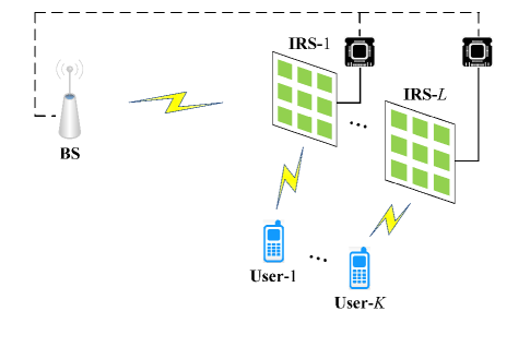
Consider an IRS-assisted massive MIMO system, where multiple IRSs are deployed to assist the BS equipped with antennas to simultaneously serve () single-antenna users in the same time-frequency resource. Suppose IRSs are employed, and the number of reflecting units at each IRS is denoted by (). Let denote the channel from the BS to the th IRS, and denote the channel from the th IRS to the th user. In this paper, we neglect the direct link from the BS to each user in order to simplify our analysis and better understand the impact of IRSs on the system performance. Also, in this paper, we assume
-
A1
The channel between the BS and each IRS is line-of-sight (LOS) dominated and has a rank-one structure.
This assumption is very likely to be met in practice because the IRS is usually installed on the facade of a high rise building in the vicinity of the BS [16]. As a result, the channel matrix between the BS and the IRS is dominated by the LOS component. Particularly, for mmWave frequency bands, measurement campaigns have shown that the power of LOS path is much higher than the sum of power of NLOS paths [29]. Thus the channel can be well-approximated as a rank-one matrix. Specifically, the BS-IRS channel can be expressed as
| (1) |
where is the complex gain, , , and are the associated azimuth angle of arrival (AoA), elevation AoA, and azimuth angle of departure (AoD) respectively, and () is the array response vector associated with the IRS (BS). Due to the rank-one structure of the BS-IRS channel, we need to assume
-
A2
The number of IRSs is no less than the number of users, i.e. .
Otherwise it is impossible for the BS to serve users simultaneously. On the other hand, as a cost-effective and energy-efficient technology, it is envisioned that, in future wireless networks, IRSs are densely deployed to provide favorable propagation environments. In addition, we assume
-
A3
The transmit array response vectors are near orthogonal to each other, i.e. for .
Such an assumption is reasonable because to enhance the signal coverage, IRSs are usually deployed surrounding the BS and as a result, the AoD parameters are expected to be sufficiently separated from each other. Particularly, when a large number of antennas are employed at the BS, the near-orthogonality property holds valid even for slightly separated AoD parameters .
With the aid of a smart micro controller, each element of the IRS can independently reflect the incident signal with a reconfigurable phase shift [17]. Therefore the composite channel between the BS and the th user is given by
| (2) |
where
| (3) |
is the phase-shift matrix associated with the th IRS, in which denotes the phase shift associated with the th passive element of the th IRS. The signal received at the th user can then be expressed as
| (4) |
where with is the transmit beamforming vector for the th user, is the transmitted symbol for the th user which is assumed to be independent and identically distributed (i.i.d.) random variables with unit variance, is the transmit power allocated for the th user and we have the constraint , in which is the total transmit power, and denotes the additive complex Gaussian noise with zero mean and variance . Therefore, the signal to interference plus noise ratio (SINR) of the th user is given by
| (5) |
Assuming the knowledge of the global channel state information, our objective is to devise the transmit precoding vectors , the transmit power allocation , and the phase shift matrices to maximize the minimum SINR among SINRs associated with all users. Such a problem can be formulated as a max-min problem:
| s.t. | ||||
| (6) |
In the following, we will show that IRS equipped with a large number of passive elements enjoys an appealing automatic interference cancelation property. By resorting to such a property, the above max-min problem can be converted into an IRS-user association problem, which can be analytically solved.
III Proposed Method
Our proposed method can be divided into two steps. In the first step, given passive beamforming parameters , we optimize active beamforming parameters, i.e. the transmit precoding vectors and the transmit power . The optimal active beamforming parameters are then substituted into (6) to obtain a passive beamforming problem. In the second step, we proposed an effective and analytical solution to this passive beamforming problem.
III-A Active Beamforming Optimization
Given , we now discuss how to solve the active beamforming problem. Note that when the IRS parameters are fixed, this problem is simplified as a max-min SINR problem for conventional massive MIMO systems, and its solution has already been proposed in [30, 31]. To gain insight into the problem, let us focus on the transmit power allocation problem first by assuming the precoding vectors are fixed. The transmit power allocation problem can be cast as
| s.t. | (7) |
By introducing an auxiliary variable , the problem (7) can be rewritten as
| s.t. | ||||
| (8) |
Using the Karush-Kuhn-Tucker(KKT) conditions and noting that all inequalities of (8) become equalities at the optimal point, it can be shown [30] that the optimal solution and satisfy the following conditions
| (9) | ||||
| (10) | ||||
| (11) | ||||
| (12) | ||||
| (13) | ||||
| (14) | ||||
| (15) |
where and are optimal Lagrange dual variables. From (9), (10), and (11), we can arrive at
| (16) |
The above KKT condition (11) indicates that the transmit precoding vector can be found via
| s.t. | (17) |
whose optimal solution is given by
| (18) |
Substituting (18) into (11), we have
| (19) |
Based on (16) and (19), can be obtained via a fixed-point iteration method. Specifically, we first randomly generate as the initial point. At the th iteration, we calculate
| (20) |
and then update
| (21) |
After is obtained, can then be calculated from (16) and (19):
| (22) |
Now, define , , and
| (27) |
Equation (9) can be expressed as . Therefore the optimal transmit power can be obtained as
| (28) |
III-B Passive Beamforming Optimization
From (22), the joint beamforming problem (6) can be simplified as a passive beamforming problem:
| s.t. | (29) |
Note that in the above optimization, both the composite channel vectors and are dependent on . Our objective is to devise the phase shift parameters to maximize the SINR . Such a problem, however, is challenging due to the non-convexity of the objective function. Moreover, cannot be expressed as an explicit function of , which further complicates the problem. In the following, we will convert the above problem into a more amiable form which helps us gain insight into the problem.
Substituting (1) into (2), the composite channel can be expressed as
| (30) |
where
| (31) | ||||
| (32) | ||||
| (33) |
From (30), we see that the composite channel from the BS to the th user, , is a linear combination of the transmit array response vectors , with each transmit array response vector weighted by . The weight is referred to as the “passive beamforming gain” from the th IRS to the th user. Substituting (30) into the objective function of (29), we arrive at
| (34) |
where , and .
Since the steering vectors are mutually orthogonal with each other (see A3), there exists a matrix such that is a unitary matrix, i.e. . Using this fact and the Woodbury matrix identity, we have
| (37) | ||||
| (40) | ||||
| (43) | ||||
| (44) |
where
Therefore the passive beamforming problem (29) becomes
| s.t. | (45) |
Denote
| (46) |
as the passive beamforming matrix with its th entry given by . Clearly, to maximize the SINR , on one hand, we wish to make the passive beamforming gains as large as possible; on the other hand, we wish to be orthogonal to each other such that the cross-interference term is minimized. A key insight here is that when the phase shift parameters of the th IRS are optimally tuned to serve the th user, i.e. is maximized, due to the asymptotic orthogonality among channel vectors associated with different users, this IRS will be like non-existent and interference-free to other users, i.e. for . In this case, each row of the passive beamforming matrix contains only a single nonzero element, and as a result, its columns are mutually orthogonal. Such a property, termed as automatic interference cancelation (AIC), will be rigorously proved in Section IV. This property is important as it can help avoid complicated inter-IRS interference management.
Based on the AIC property, a simple yet effective solution is to divide IRSs into disjoint groups, with parameters of each group of IRSs optimally tuned to serve one particular user. This problem is referred to as a user association problem. This solution is effective because, on one hand, it can achieve a reasonably large for each ; on the other hand, the cross-interference term disappears due to the orthogonality among . To formulate this user association problem, define as the maximum achievable passive beamforming gain. From (31), it can be easily verified that is given by
| (47) |
which is attained when parameters associated with the th IRS are set as
| (48) |
where represents the argument of the complex number , and denote the th entry of and , respectively. Let . The IRS-user association problem can be formulated as
| s.t. | ||||
| (49) |
where entries of are chosen either to be or 0, denotes the th row of , and the constraint is due to the AIC property, i.e. when the phase shift parameters of the th IRS are optimally tuned to serve a certain user, this IRS will become interference-free to other users. Altogether, is constructed by keeping only one element for each row of and setting the rest elements of equal to zero. Since we can choose any element from each row of , the number of feasible solutions is up to , from which we need to choose the one that maximizes the objective function in (49).
The simplest method to solve (49) is to exhaustively search all feasible solutions. When and are small, say , the computational complexity of this exhaustive search scheme is still practical. For the scenario where a large number of IRSs are deployed, we develop a greedy algorithm to search for the best IRS-user association. Specifically, we first choose the largest passive beamforming gain from , say is the largest (in terms of magnitude) in . Based on this result, the th IRS is allocated to the th user. Next, we nullify the th IRS and the th user by setting entries on the th row and the th column of equal to zero. Thus we obtain an updated passive beamforming gain matrix, denoted as . Then we choose the largest element (in terms of magnitude) in , say , and let the th IRS assigned to the th user. Again, the passive beamforming gain matrix is updated by setting entries of the th row and the th column of equal to zero. This procedure is repeated until each user is served by an IRS. If the number of IRSs is larger than the number of users, then we need to assign extra IRSs to users. We first set the th rows of equal to zero and obtain a new matrix . Then, we choose the largest entry (in terms of magnitude) in , say , and let the th IRS assigned to the th user. Next, the passive beamforming gain matrix is updated by setting the th row of equal to zero. This procedure is repeated until all IRSs are assigned. Although this greedy algorithm is not guaranteed to yield the optimal solution, it has a very low computational complexity.
IV Automatic Interference Cancelation
In the previous section, we propose an effective solution that converts the passive beamforming problem into a user association problem, based on the property that when the th IRS is optimally tuned to serve the th user, this IRS will become non-existent (i.e. interference-free) to other users. Such a property is referred to as the AIC property. In this section, we consider two typical IRS-user channel models, namely, an LOS-dominated channel model and a Rayleigh fading channel model. We will show that the AIC property holds asymptotically for both scenarios when .
IV-A LOS-Dominated IRS-User Channel
Suppose the channel between the th IRS and the th user () is dominated by the LOS component, which is usually the case for mmWave communications [32]. In this case, can be written as
| (50) |
where is the complex gain between the th IRS and the th user, () is the associated azimuth (elevation) AoD, and is the array response vector associated with the IRS. Assume a uniform planar array (UPA) is used at each IRS, the steering vector can be expressed as
where () denotes the number of elements along the horizontal (vertical) axis, , and is the coordinate of the reflecting element. From (31), we know that is given by
| (51) |
where denotes the phase shift parameter of the th IRS’s reflecting element at the coordinate , and
| (52) |
It is clear that is maximized when
| (53) |
When the parameters of the th IRS are optimally tuned to serve the th user, we now show that this IRS becomes interference-free to other users in an asymptotic sense, i.e. as for any . We have
| (54) |
where
| (55) |
Suppose the locations of different users are well separated such that and , . Then we have
| (56) |
Hence the AIC property holds in an asymptotic sense as .
IV-B Rayleigh Channel
For the scenario where there is no dominant propagation along an LOS between the IRS and the user, the channel can be modeled as an independent and identically distributed (i.i.d.) Rayleigh fading channel [13], i.e.
| (57) |
where is a factor that depends on the distance between the th IRS and the th user. According to (48), the passive beamforming gain is maximized when
| (58) |
where and denote the th entry of and , respectively. The can then be calculated as
| (59) |
where . Since are i.i.d. with , according to Khinchin’s law of large numbers, we have
| (60) |
for any , i.e.
| (61) |
when . Therefore, the AIC property holds asymptotically for the Rayleigh channel.
V Performance Analysis
In this section, we provide a theoretical analysis of our proposed method. Specifically, given the global channel state information and , we analyze the max-min SINR attained by our proposed solution. According to (45), the max-min SINR is given by
| (62) |
In the previous section, we have shown that the AIC property holds asymptotically for both LOS-dominated and Rayleigh fading channels. In other words, when the parameters of the th IRS are optimally tuned to serve the th user, this IRS is interference-free to other users. As a result, vectors are orthogonal to each other, and we have
| (63) |
where is the set of indices of IRSs that serve the th user, is the number of IRSs that serve the th user with , and
| (64) |
is a constant that depends on the realization of the channel . Suppose the channel is a LOS-dominated channel given by (50). Then can be further calculated as
| (65) |
From (65), we can see that the SINR is in the order of , which scales quadratically with the number of reflecting elements . Such a “squared improvement” has also been reported in previous IRS-assisted works, e.g. [14, 15]. Nevertheless, to our best knowledge, our work seems to be the first to show that the squared improvement also holds valid for multi-user systems. Also, (65) suggests that, even with a moderate number of active antennas at the BS, increasing the number of passive elements can help achieve a massive MIMO like gain, thereby significantly reducing the energy consumption at the BS.
VI Simulation Results
We now provide simulation results to illustrate the performance of our proposed joint active and passive beamforming solution. In our simulations, the BS employs a ULA with antennas, and each IRS consists of a uniform planar array (UPA) with reflecting elements, where and denote the number of elements along the horizontal axis and vertical axis, respectively. Throughout our simulations, we fix , and increase to obtain different values of . The channel from the BS to the th IRS is characterized by the rank-one geometric channel model (1), in which the complex gain is generated according to a complex Gaussian distribution
| (66) |
where is characterized by a distance-dependent path loss model given by [33]
| (67) |
is the distance between the BS and the th IRS, is the path loss at the reference distance meter, and denotes the path loss exponent of the LOS-dominant channel. The channel between the th IRS and the th user () is given by (50), in which the complex gain is generated according to a complex Gaussian distribution
| (68) |
where is given by
| (69) |
is the distance between the th IRS and the th user. Some related parameters are set as follows: dBm, dBm, dB, and .
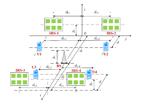
We first examine the validity of the AIC property. Consider a three-dimensional setup, where four IRSs are used to serve four users, see Fig. 2. The BS is located on the -axis with its coordinate given by , where we set m and m. The four IRSs, named as IRS-1, IRS-2, IRS-3 and IRS-4, are located at , , , and , respectively, and we set m, m. The coordinates of the four users, namely U1, U2, U3, and U4, are set to , , , and , respectively, where , , , and are uniformly generated from m. To validate the AIC property, we compare our proposed joint active and passive beamforming solution with the theoretical result (65) obtained by neglecting the cross-interference terms.
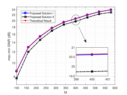
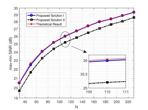
Fig. 3 plots the max-min SINR of our proposed solutions as a function of the number of reflecting elements , where we set m and . For the theoretical result (65) and the proposed solution I, an exhaustive search scheme is employed to solve the user association problem (49), while the proposed solution II uses the greedy algorithm to solve (49). From Fig. 3, we see that doubling the number of reflecting elements achieves a gain of about dB, which corroborates our theoretical analysis that the max-min SINR increases quadratically with the number of reflecting elements. In addition, from Fig. 3 we see that our proposed solution I attains performance close to the theoretical result (65). This result indicates that the AIC property holds well even for a moderate number of reflecting elements. In Fig. 4, we plot the max-min SINR of our proposed solutions as a function of , where we set m and . From Fig. 4, we see that doubling the number of antennas at the BS leads to about dB gain, which corroborates our theoretical result that the max-min SINR increases linearly with the number of antennas at the BS. Also, our proposed solution I coincides well with the theoretical result (65) for different values of . This is because the AIC property holds irrespective of the choice of .
Next, we compare our proposed solution with a conventional massive MIMO system without deploying IRSs. For the conventional massive MIMO system, the channel between the BS and the th user is characterized by a geometric channel
| (70) |
where represents the complex gain of the th path, is the number of paths, and is the azimuth AoD of the th path. The complex gain is generated from the following complex Gaussian distribution
| (71) |
where is given by
| (72) |
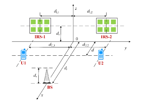
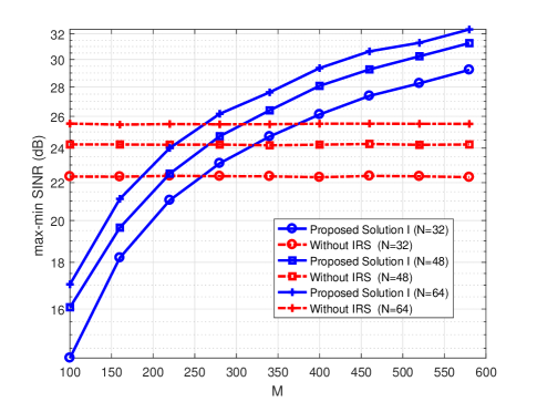
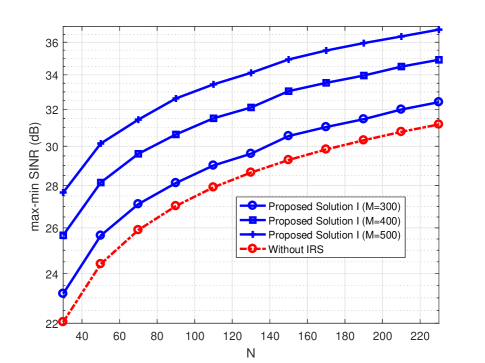
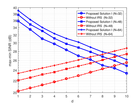
in which the path loss exponent is set to , and denotes the distance between the BS and the th user. Note that for the conventional massive MIMO system, the max-min SINR can be obtained by substituting (70) into (22). The simulation setup is depicted in Fig. 5, where the coordinates of the BS, IRS-1, IRS-2, U1, and U2 are the same as those in Fig. 2. Fig. 6 plots the max-min SINR as a function of for different choices of , where we set m. Fig. 7 depicts the max-min SINR as a function of for different values of , where we set m. From Fig. 6 and Fig. 7, we see that the IRS-assisted system outperforms the conventional massive MIMO system when , and this advantage becomes more pronounced as the number of reflect elements increases. Fig. 6 and Fig. 7 also suggest that by increasing the number of passive reflecting elements, one can achieve a same performance with much fewer active antennas, therefore substantially reducing the energy consumption at the BS. Fig. 8 plots the max-min SINR as a function of for different values of , where we set . From Fig. 8, we see that the max-min SINR improves substantially as users move closer to IRSs, thus creating a signal hotspot in the vicinity of IRSs.
VII Conclusions
In this paper, we studied the problem of joint active and passive beamforming for IRS-assisted massive MIMO systems, where multiple IRSs equipped with a large number of passive elements are deployed to assist the BS to simultaneously serve a small number of single-antenna users. We aimed to maximize the minimum SINR at users by jointly optimizing the transmit precoding vector, the transmit power, and the phase shift parameters. To address this problem, we first proved an important and appealing property, referred to as AIC. The key idea is that when an IRS is optimally tuned to serve a certain user, this IRS will become interference-free to other users. By resorting to this property, we came up with a simple yet effective solution to the joint beamforming problem. Theoretical and simulation results revealed that our proposed solution attains an SINR that scales quadratically with the number of reflecting elements, and suggest that, even with a moderate number of active antennas at the BS, a massive MIMO like gain can be achieved via increasing the number of passive reflecting elements.
References
- [1] F. Rusek, D. Persson, B. K. Lau, E. G. Larsson, T. L. Marzetta, O. Edfors, and F. Tufvesson, “Scaling up MIMO: Opportunities and challenges with verylarge arrays,” IEEE Signal Process. Mag., vol. 30, no. 1, pp. 40–60, Jan. 2013.
- [2] E. G. Larsson, O. Edfors, F. Tufvesson, and T. L. Marzetta, “Massive MIMO for next generation wireless systems,” IEEE Commun. Mag., vol. 52, no. 2, pp. 186–195, Feb. 2014.
- [3] T. L. Marzetta, “Noncooperative cellular wireless with unlimited numbers of base station antennas,” IEEE Trans. Wireless Commun., vol. 9, no. 11, pp. 3590–3600, Nov. 2010.
- [4] S. Buzzi, C.-L. I, T. E. Klein, H. V. Poor, C. Yang, and A. Zappone, “A survey of energy-efficient techniques for 5G networks and challenges ahead,” IEEE J. Sel. Areas Commun., vol. 34, no. 4, pp. 697–709, April 2016.
- [5] S. Zhang, Q. Wu, S. Xu, and G. Y. Li, “Fundamental green tradeoffs: Progresses, challenges, and impacts on 5G networks,” IEEE Commun. Surveys Tuts., vol. 19, no. 1, pp. 33–56, Firstquarter 2017.
- [6] X. Tan, Z. Sun, D. Koutsonikolas, and J. M. Jornet, “Enabling indoor mobile millimeter-wave networks based on smart reflect-arrays,” in IEEE INFOCOM 2018 - IEEE Conference on Computer Communications, Honolulu, HI, USA, April 16-19 2018, pp. 270–278.
- [7] O. Abari, D. Bharadia, A. Duffield, and D. Katabi, “Enabling high quality untethered virtual reality,” in 14th USENIX Symposium on Networked Systems Design and Implementation (NSDI 17), Boston, MA: USENIX Association, March 27-29, 12-17 2017, pp. 531–544.
- [8] C. Liaskos, S. Nie, A. Tsioliaridou, A. Pitsillides, S. Ioannidis, and I. Akyildiz, “A new wireless communication paradigm through software-controlled metasurfaces,” IEEE Commun. Mag., vol. 56, no. 9, pp. 162–169, Sep. 2018.
- [9] S. Hu, F. Rusek, and O. Edfors, “Beyond massive MIMO: The potential of data transmission with large intelligent surfaces,” IEEE Trans. Signal Process., vol. 66, no. 10, pp. 2746–2758, May 2018.
- [10] Y.-C. Liang, R. Long, Q. Zhang, J. Chen, H. V. Cheng, and H. Guo, “Large intelligent surface/antennas (LISA): Making reflective radios smart,” available at arXiv: 1906.06578, 2019.
- [11] Q. Wu and R. Zhang, “Towards smart and reconfigurable environment: Intelligent reflecting surface aided wireless network,” available at arXiv: 1905.00152, 2019.
- [12] C. Huang, G. C. Alexandropoulos, A. Zappone, M. Debbah, and C. Yuen, “Energy efficient multi-user MISO communication using low resolution large intelligent surfaces,” in 2018 IEEE Globecom Workshops (GC Wkshps), Abu Dhabi, United Arab Emirates, Dec. 9-13 2018, pp. 1–6.
- [13] Q. Wu and R. Zhang, “Beamforming optimization for intelligent reflecting surface with discrete phase shifts,” in ICASSP 2019 - 2019 IEEE International Conference on Acoustics, Speech and Signal Processing (ICASSP), Brighton, United Kingdom, May, 12-17 2019, pp. 7830–7833.
- [14] ——, “Intelligent reflecting surface enhanced wireless network: Joint active and passive beamforming design,” in 2018 IEEE Global Communications Conference (GLOBECOM), Abu Dhabi, United Arab Emirates, Oct., 9-13 2018, pp. 1–6.
- [15] P. Wang, J. Fang, X. Yuan, Z. Chen, H. Duan, and H. Li, “Intelligent reflecting surface-assisted millimeter wave communications: Joint active and passive precoding design,” available at arXiv: 1908.10734, 2019.
- [16] Q.-U.-A. Nadeem, A. Kammoun, A. Chaaban, M. Debbah, and M.-S. Alouini, “Asymptotic analysis of large intelligent surface assisted MIMO communication,” available at arXiv: 1903.08127, 2019.
- [17] Q. Wu and R. Zhang, “Intelligent reflecting surface enhanced wireless network via joint active and passive beamforming,” IEEE Trans. Wireless Commun., vol. 18, no. 11, pp. 5394–5409, Nov. 2019.
- [18] Y. Han, W. Tang, S. Jin, C.-K. Wen, and X. Ma, “Large intelligent surface-assisted wireless communication exploiting statistical CSI,” IEEE Trans. Veh. Technol., vol. 68, no. 8, pp. 8238–8242, Aug. 2019.
- [19] Q. Wu and R. Zhang, “Joint active and passive beamforming optimization for intelligent reflecting surface assisted SWIPT under QoS constraints,” available at arXiv: 1910.06220, 2019.
- [20] P. Wang, J. Fang, H. Duan, and H. Li, “Compressed channel estimation and joint beamforming for intelligent reflecting surface-assisted millimeter wave systems,” available at arXiv: 1911.07202, 2019.
- [21] Z.-Q. He and X. Yuan, “Cascaded channel estimation for large intelligent metasurface assisted massive MIMO,” IEEE Wireless Commun. Lett., pp. 1–1, 2019.
- [22] C. Huang, A. Zappone, M. Debbah, and C. Yuen, “Achievable rate maximization by passive intelligent mirrors,” in 2018 IEEE International Conference on Acoustics, Speech and Signal Processing (ICASSP), Calgary, AB, Canada, April 15-20 2018, pp. 3714–3718.
- [23] Y. Yang, S. Zhang, and R. Zhang, “IRS-enhanced OFDM: Power allocation and passive array optimization,” available at arXiv: 1905.00604, 2019.
- [24] M. Cui, G. Zhang, and R. Zhang, “Secure wireless communication via intelligent reflecting surface,” IEEE Wireless Commun. Lett., vol. 8, no. 5, pp. 1410–1414, Oct. 2019.
- [25] X. Yu, D. Xu, and R. Schober, “Enabling secure wireless communications via intelligent reflecting surfaces,” available at arXiv: 1904.09573, 2019.
- [26] H. Shen, W. Xu, S. Gong, Z. He, and C. Zhao, “Secrecy rate maximization for intelligent reflecting surface assisted multi-antenna communications,” IEEE Commun. Lett., vol. 23, no. 9, pp. 1488–1492, Sep. 2019.
- [27] X. Guan, Q. Wu, and R. Zhang, “Intelligent reflecting surface assisted secrecy communication via joint beamforming and jamming,” available at arXiv: 1907.12839, 2019.
- [28] D. Mishra and H. Johansson, “Channel estimation and low-complexity beamforming design for passive intelligent surface assisted MISO wireless energy transfer,” in ICASSP 2019 - 2019 IEEE International Conference on Acoustics, Speech and Signal Processing (ICASSP), Brighton, United Kingdom, May 12-17 2019, pp. 4659–4663.
- [29] Z. Muhi-Eldeen, L. Ivrissimtzis, and M. Al-Nuaimi, “Modelling and measurements of millimetre wavelength propagation in urban environments,” IET Microwaves, Antennas Propag., vol. 4, no. 9, pp. 1300–1309, Sept. 2010.
- [30] D. W. H. Cai, T. Q. S. Quek, and C. W. Tan, “A unified analysis of max-min weighted SINR for MIMO downlink system,” IEEE Trans. Signal Process., vol. 59, no. 8, pp. 3850–3862, Aug. 2011.
- [31] C. W. Tan, M. Chiang, and R. Srikant, “Maximizing sum rate and minimizing mse on multiuser downlink: Optimality, fast algorithms and equivalence via max-min SINR,” IEEE Trans. Signal Process., vol. 59, no. 12, pp. 6127–6143, Dec 2011.
- [32] S. Hur, T. Kim, D. J. Love, J. V. Krogmeier, T. A. Thomas, and A. Ghosh, “Millimeter wave beamforming for wireless backhaul and access in small cell networks,” IEEE Trans. Commun., vol. 61, no. 10, pp. 4391–4403, Oct. 2013.
- [33] V. Erceg, L. J. Greenstein, S. Y. Tjandra, S. R. Parkoff, A. Gupta, B. Kulic, A. A. Julius, and R. Bianchi, “An empirically based path loss model for wireless channels in suburban environments,” IEEE J. Sel. Areas Commun., vol. 17, no. 7, pp. 1205–1211, July 1999.