Role of axial twin boundaries on deformation mechanisms in Cu nanopillars
Abstract
In recent years, twinned nanopillars have attracted tremendous attention for research due to their superior mechanical properties. However, most of the studies were focused on nanopillars with twin boundaries (TBs) perpendicular to loading direction. Nanopillars with TBs parallel to loading direction have received minimal interest. In this backdrop, the present study is aimed at understanding the role of axial TBs on strength and deformation behaviour of Cu nanopillars using atomistic simulations. Tensile and compression tests have been performed on 112 nanopillars with and without TBs. Twinned nanopillars with twin boundary spacing in the range 1.6-5 nm were considered. The results indicate that, under both tension and compression, yield strength increases with decreasing twin boundary spacing and is always higher than that of perfect nanopillars. Under compression, the deformation in 112 perfect as well as twinned nanopillars proceeds by the slip of extended dislocations. In twinned nanopillars, an extensive cross-slip by way of Friedel-Escaig and Fleischer mechanisms has been observed in compression. On the other hand, under tensile loading, the deformation in perfect nanopillars occurs by partial slip/twinning, while in twinned nanopillars, it proceeds by the slip of extended dislocations. This extended dislocation activity is facilitated by stair-rod formation and its dissociation on the twin boundary. Similar to compressive loading, the extended dislocations under tensile loading also exhibit cross-slip activity in twinned nanopillars. However, this cross-slip activity occurs only through Fleischer mechanism and no Friedel-Escaig mechanism of cross-slip has been observed under tensile loading.
keywords:
Atomistic simulations; Nanopillars; Twin boundaries; Dislocations; Cross-slip1 Introduction
In the last couple of years, the twinned nanowires/nanopillars received tremendous attention for research due to their superior mechanical performances. Twinned nanowires exhibit enhanced strength without loss of ductility [1, 2], improves crack resistance [3], and show high strain rate sensitivity [4]. The twin boundaries in nanowires can also acts as a source/sink and also as a glide plane for dislocations [5]. In nanowires, the presence of twin boundaries influences the plastic flow by way of strain hardening or strain softening or in some cases, without any hardening or softening, which depends on twin boundary orientation, twin boundary spacing, nanowire size and shape [6, 7, 8, 9]. For example, Zhang and Huang [7] reported that in nanowires, the strengthening or softening due to twin boundaries depends on the cross-section shape of the nanowire. In a square cross-section nanowire, the twin boundaries strengthen the nanowire, while in circular cross-section nanowire, the presence of twin boundaries leads to softening [7]. This difference under the influence of twin boundaries is mainly due to differences in stress required for dislocation nucleation during yielding in square and circular nanowires [7]. For nanowires with square cross-section, the presence of sharp corners lowers the stress required for dislocation nucleation, which is lower than that needed for dislocation penetration through the twin boundaries. This leads to strengthening in square cross-section nanowires. On the other hand, the nucleation stress in circular nanowires is higher, so the penetration through the twin boundaries requires no additional stress leading to the observed softening in circular nanowires. Similarly, Sun et al. [9] have investigated the combined influence of twin boundary spacing and nanowire length. It has been reported that long nanowires with length (L) 450 nm always exhibit brittle failure, while short nanowires with L 200 nm invariably fails in ductile manner, irrespective of twin boundary spacing. However, the nanowires with intermediate lengths (200 nm L 450 nm) have shown a ductile to brittle transition with increasing twin boundary spacing (high ductility for low twin boundary spacing) [9].
Apart from influencing the strength and ductility, the twinned nanopillars have shown novel deformation mechanisms [5, 10, 11, 12]. Generally, dislocations in FCC materials such as Cu glide on planes. However, in twinned nanowires, the dislocations glide on plane after penetrating the twin boundary [10]. In another study, Wang and Sui [11] have shown that the leading and trailing partials can exchange their order after passing through the twin boundary. Using atomistic simulations and in-situ experiments, Jang et al. [12] reported a brittle to ductile transition in orthogonally twinned Cu nanopillars with decreasing twin boundary spacing. Further, the twin boundary orientation also affects the deformation mechanisms in FCC nanopillars. Due to special geometry, the twin boundaries orientated at different angles with respect to the loading direction possess distinct interactions with dislocations, which results in different deformation mechanisms [12, 13, 14, 15]. In nanopillars with orthogonal twin boundaries (twin boundaries perpendicular to the loading direction), the twin boundary-dislocation interactions dominate the plastic flow and increases the flow stress, whereas de-twinning governs deformation in nanopillars with slanted twin boundaries (twin boundaries oriented other than and with respect to loading direction) [12]. In nanopillars with orthogonal twin boundaries, different dislocation-twin interactions such as dislocation transmission across the twin boundary, stair-rod formation and dislocation multiplication have been observed. Afanasyev and Sansoz [16] have reported the formation and dissociation of Lomer-Cottrell locks during the dislocation-twin boundary interactions in Au nanopillars. Further, the dislocations with Burgers vector parallel to the twin plane, can either propagate into the adjacent twin grain by cutting through the boundary, or be absorbed and dissociate within the boundary plane [16, 17]. Similarly, Jang et al. [12] have reported that the dislocation-twin boundary interactions leads to entanglement and multiplication without any change in twin boundary spacing in orthogonally twinned nanopillars. In contrary to orthogonally twinned nanopillars, the motion of Shockley partials along the twin boundary leading to twin boundary migration and de-twinning has been observed in nanopillars with slanted twin boundaries [12, 15].
Most of the studies mentioned above were focused on the nanowires with orthogonal or slanted twin boundaries. Little has been investigated on twinned nanowires when the twin boundaries are parallel to the loading direction (axial or longitudinal twin boundaries). In longitudinally twinned nanowires, mainly two loading directions (110 and 112) have been investigated in the literature, with more focus on 110. In 110 oriented longitudinally twinned FCC nanowires, it has been shown that the introduction of twin boundary changed the deformation mode from twinning in perfect nanowires to slip in twinned nanowires [13, 18]. Similarly, Jeon and Dehm [19] have observed the formation of intensive dislocation networks on the axial twin boundary under both 110 or 112 loading directions. Further, the type of dislocation network strongly depends on the nanowire orientation. In 110 loading direction, a high density of sessile dislocation networks formed at the twin boundary, while in 112 loading direction, a lower density of glissile dislocation networks was observed [19]. In nanopillar containing a single axial twin boundary, Cheng et al. [20] reported the complete annihilation of twin boundary leading to the formation of a single crystal, which has been attributed to anomalous de-twinning mechanism. However, the influence of twin boundary spacing has not been investigated when the twin boundaries are parallel to the loading direction. Although, under tensile loading, it has been shown that the introduction of longitudinal twin boundary increases the strength of the nanowire compared to its perfect counterpart [13], but the influence of twin boundary spacing is still elusive. Further in twinned nanopillars, the dislocation interactions with twin boundaries needs to be investigated in greater detail. For example, how the dislocations transmit/cross-slip across/onto twin boundaries is still ambiguous [8]. With these multiple motivations, an attempt has been made in this paper to understand the spacing dependence of yield strength, deformation mechanisms, different dislocation-twin interactions and possible dislocation cross-slip mechanisms under tensile and compressive loading of 112 oriented longitudinally twinned Cu nanopillars. The twin boundaries have been introduced parallel to the loading direction (112) and number of twin boundaries varied from 1 to 5, which results in twin boundary spacing in the range 1.6-5 nm.
2 Computational details
Molecular dynamics (MD) simulations have been performed using Large scale Atomic/Molecular Massively Parallel Simulator (LAMMPS) package [21] employing an embedded atom method (EAM) potential for FCC Cu developed by Mishin and co-workers [22]. This potential has been chosen for being able to reproduce generalized stacking fault and twinning fault energies for Cu [23], which are key variables for predicting the dislocation and plasticity related properties. AtomEye [24] and OVITO [25] packages have been used for the visualisation and analysis of deformation mechanisms. Common neighbour analysis (CNA) as implemented in AtomEye and OVITO and dislocation extraction algorithm [26] as implemented in OVITO have been used to identify the stacking faults and various type of dislocations based on the Burgers vector.
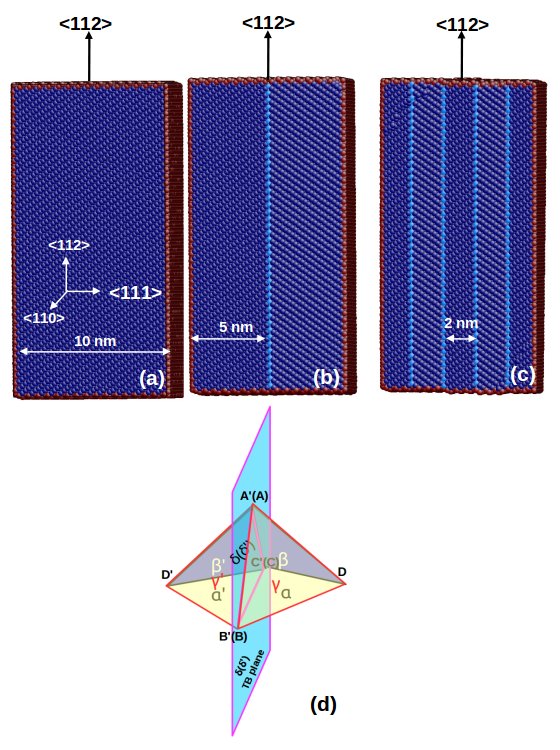
In order to create a longitudinal twin boundary, the procedure followed in Ref. [27] has been adapted. First, a defect free Cu nanopillar of square cross section width (d) = 10 nm, oriented in 112 axial direction with {110} and {111} as side surfaces has been chosen. The nanopillar length (l) was twice the cross section width (d) and no periodic boundary conditions were used in any direction. Then, the nanowire has been divided into two equal parts along the 111 direction and, one part of the crystal is rotated with respect to the other by . Following the rotation, a twin boundary forms at the interface, which lies on {111} plane. Similar procedure has been adapted to create more number of twin boundaries. The nanopillars containing one, two, three, four and five twin boundaries resulted in twin boundary spacings of 5.0, 3.3, 2.5, 2.0 and 1.6 nm, respectively. The typical nanopillars with different twin boundary spacings considered in this study along with perfect nanopillar are shown in Figure 1. The double Thompson tetrahedron showing the slip planes and directions in parent and twinned lattice is shown in Figure 1d. In the present study, this notation has been used to describe the various dislocation-twin boundary interactions.
Following the creation of the model nanowires, the energy minimization was performed by a conjugate gradient method to obtain a relaxed structure. To put the sample at the required temperature, all the atoms have been assigned initial velocities according to the Gaussian distribution. Following this, the nanopillar system was thermally equilibrated to a required temperature of 10 K in canonical ensemble (constant NVT) with a Nose-Hoover thermostat. The velocity verlet algorithm has been used to integrate the equations of motion with a time step of 2 fs. Following thermal equilibration, the tensile or compressive deformation was carried out in a displacement controlled mode at a constant strain rate of s-1 by imposing displacements to atoms along the axial direction (i.e., 112 axis) that varied linearly from zero at the bottom to a maximum value at the top layer. The strain () has been calculated as , where is instantaneous length and is the initial length of the nanowire. Finally, the stress has been obtained using the Virial expression [28], which is equivalent to a Cauchy’s stress in an average sense.
3 Results
3.1 Effect of twin boundaries on stress-strain behaviour and yield stress
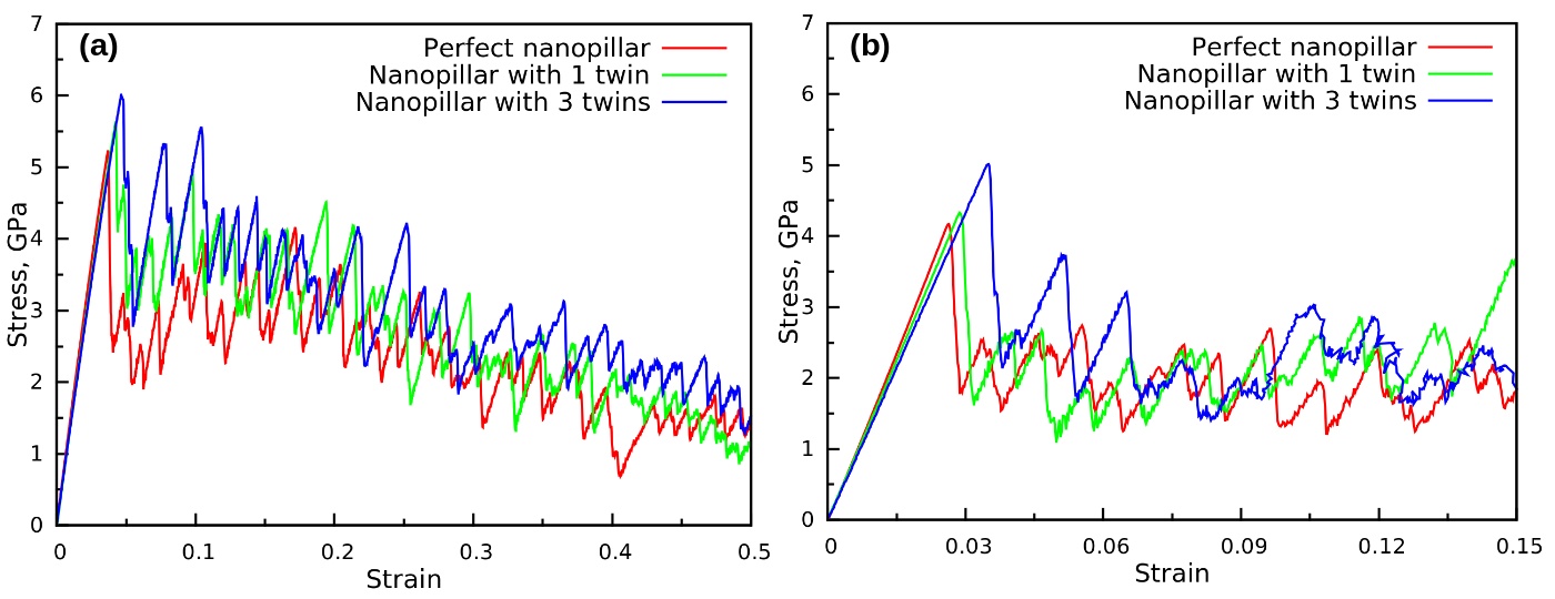
Figure 2 shows the stress-strain behaviour of perfect as well as twinned 112 Cu nanopillars subjected to tensile and compressive loading. The tensile loading has been performed until a nanopillar attains a strain of 50%, while in compression, the loading has been applied until a strain of 15%. It can be seen that, all the nanopillars exhibits a linear elastic deformation up to a maximum value of stress (designated as yield stress) followed by a precipitous drop of around 2-3 GPa. Following the drop, the flow stress under tensile loading show an overall decreasing behaviour with large fluctuations (Figure 2a). On the other hand, the flow stress under compressive loading display large fluctuations around a constant mean stress of 2 GPa (Figure 2b). The peak value of the stress-strain curve has been taken as the yield stress of the nanopillar. It can be seen that, under both tensile and compressive loading, the introduction of twin boundaries increases the strength of the nanopillar as compared to the perfect nanopillar (Figure 2). Further, higher the number of twin boundaries, higher the strength.
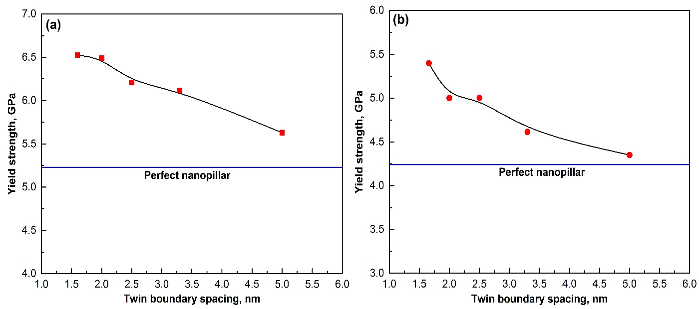
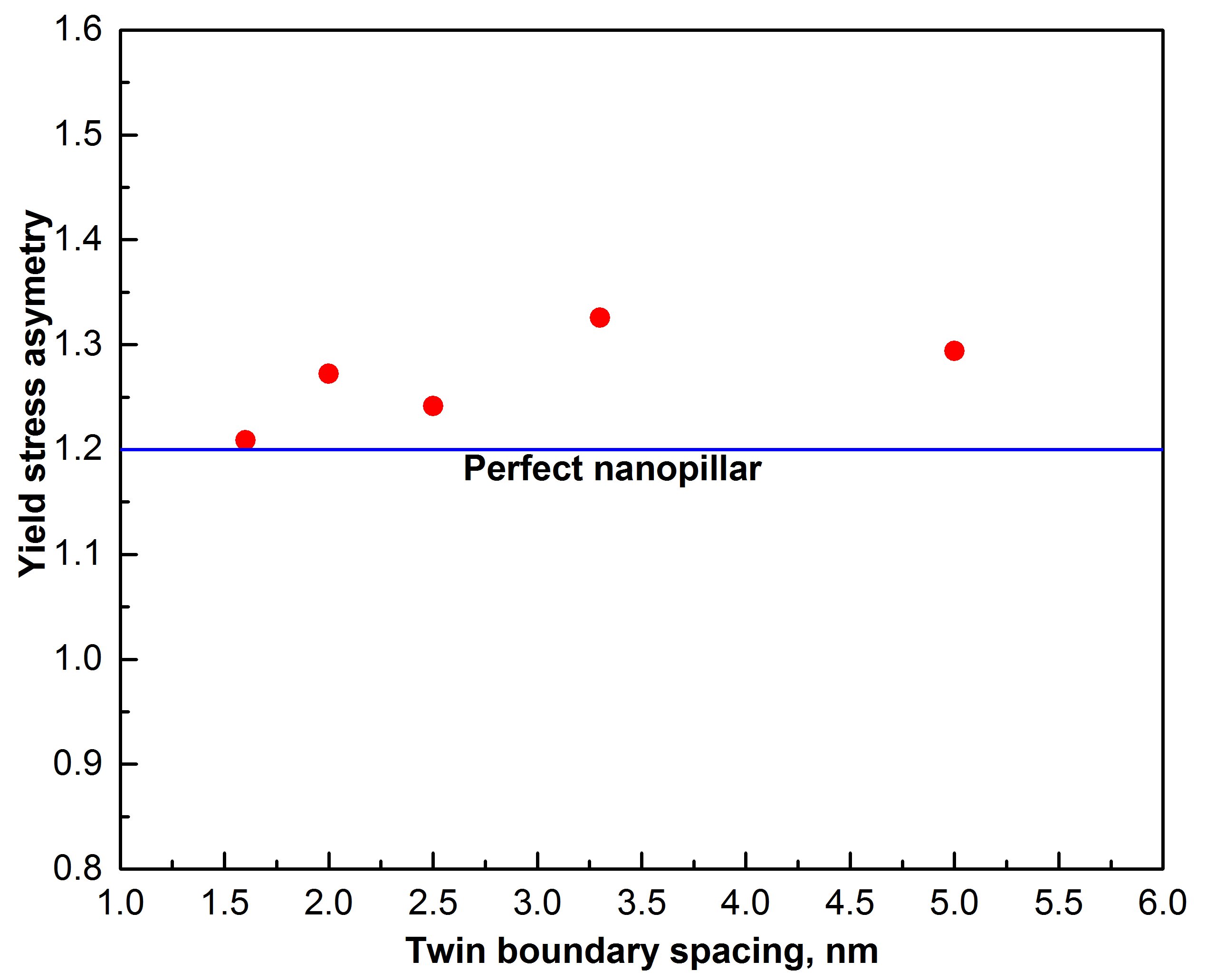
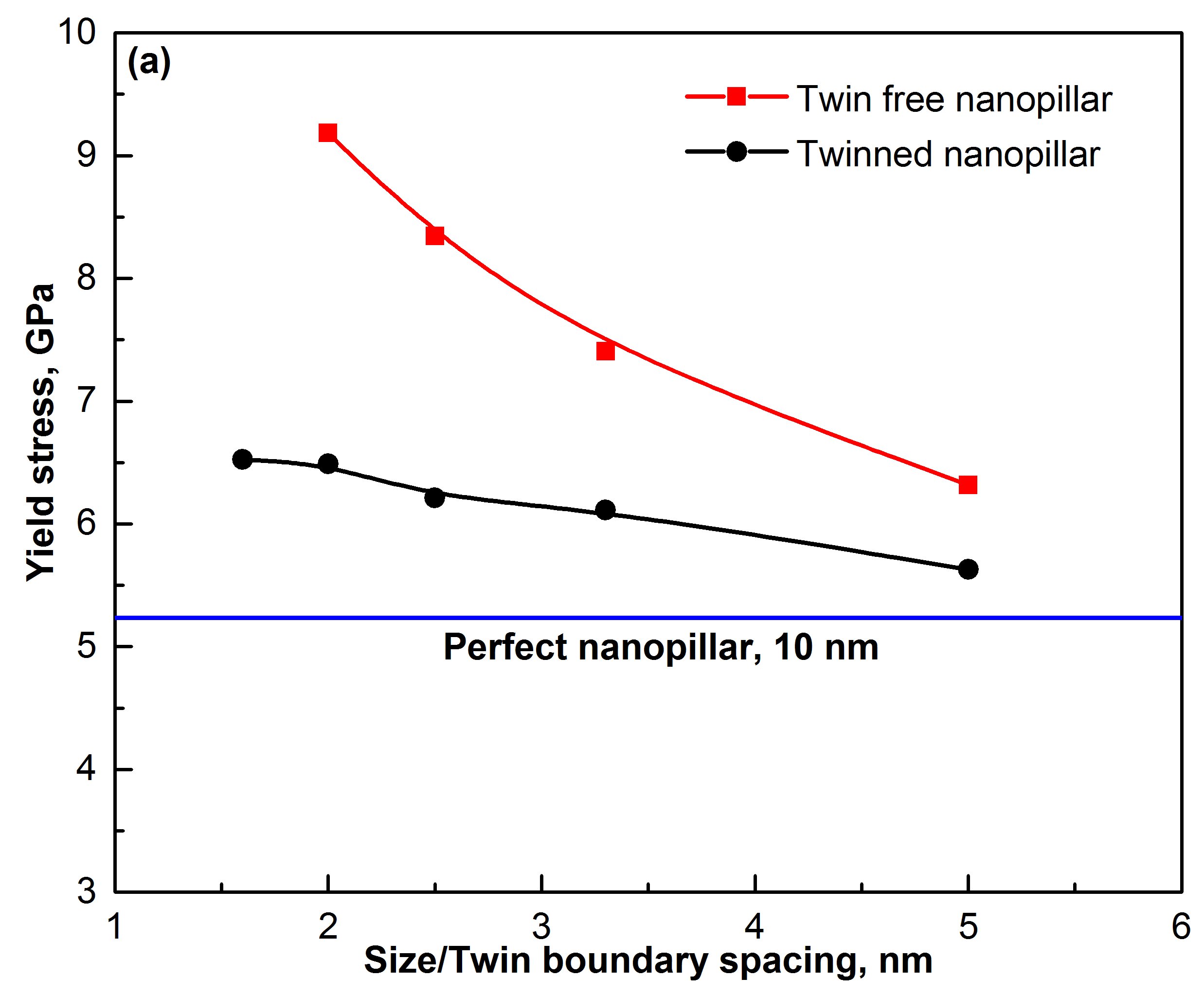
To quantify the effect of twin boundaries, the twin boundary spacing has been chosen as the variable parameter. Figure 3 shows the variation of yield stress as a function of twin boundary spacing under tensile and compressive loading. For comparison, the yield stress of perfect 112 nanopillar has been shown as a horizontal line under respective loading conditions. It can be seen that the yield stress of all the twinned nanopillars falls above the horizontal line (Figure 3), indicating that the strength of twinned nanopillars is higher the perfect twin free nanopillars. Further, the yield stress values under tensile and compressive loading decreases with increasing twin boundary spacing (Figure 3), which is similar to that observed in orthogonally twinned FCC nanopillars [1, 7, 12, 14, 16]. It can also be seen that, for perfect as well as twinned nanopillars, the yield stress values under tensile loading are higher than that in compressive loading i.e., all the nanopillars display tension-compression asymmetry in yield stress. Figure 4 shows the values of yield stress asymmetry measured as the ratio of yield stress in tension to that in compression, as a function of twin boundary spacing. The yield stress asymmetry of perfect nanopillar is obtained as 1.2, which is shown as horizontal line in Figure 4. It can be seen that the yield stress asymmetry for twinned nanopillars is different from that of the perfect nanopillars (higher the number of twin boundaries, lower the asymmetry), which indicates that the twin boundaries can also influence the tension-compression asymmetry. Previous studies have shown that the asymmetry in yield stress arises due to different values of Schmid factor for leading partials under tensile and compressive loading [29]. Further, Salehinia and Bahr [30] have shown that the asymmetry in the strength of nanowires decreases with increasing defect density, which is in agreement with the present findings.
3.2 Deformation mechanisms in perfect 112 Cu nanopillars
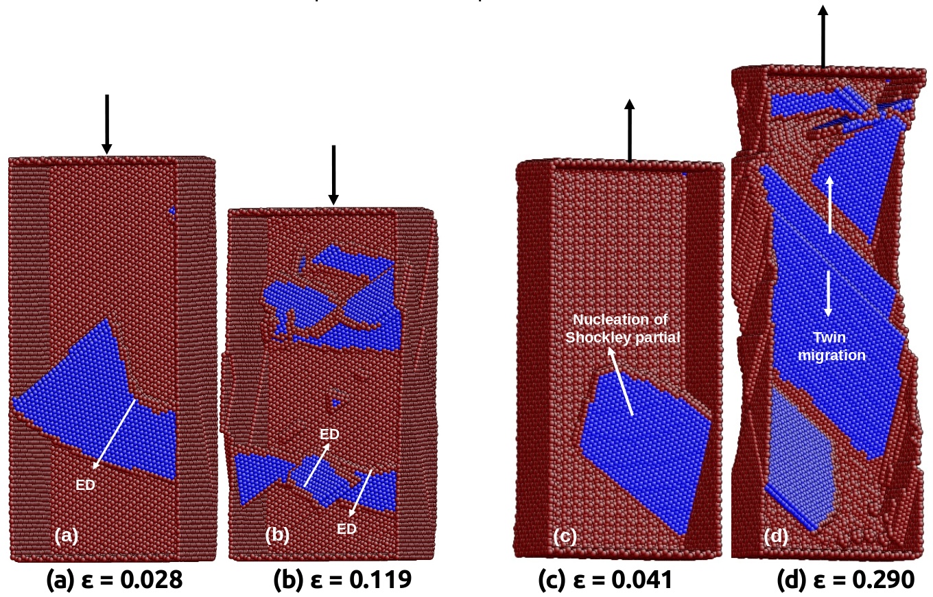
In order to understand the clear role of twin boundaries on deformation mechanisms, first, the deformation mechanisms in perfect 112 Cu nanopillars has been investigated. Figure 5 shows the deformation behaviour in perfect 112 Cu nanopillars under compressive and tensile loading. As shown in Figure 5(a-b), the deformation is governed by the slip of extended dislocations under compressive loading. An extended dislocation consist of a leading and trailing partial dislocations separated by a stacking fault. Figure 5a shows an extended dislocation nucleated during the yielding of Cu nanopillars under compressive loading. With increasing strain, the extended dislocations belonging to different slip systems interact and results in the formation of a stacking fault tetrahedron (Figure 5b). The nucleation of trailing partials under compressive loading is favoured due to its high Schmid factor value as compared to leading partial [29]. Different from compressive loading, the deformation under tensile loading of perfect 112 Cu nanopillars occurs through the slip of Shockley partial dislocations (Figure 5(c-d)). The yielding occurs through the nucleation of a Shockley partial dislocations (Figure 5c). Since the nanopillar is defect-free, the nucleated partial dislocation glides freely towards the opposite surface leaving behind a stacking fault, and also a step on the surface of nanopillar. The continuous nucleation and glide of Shockley partials on the adjacent parallel planes leads to the formation of a micro-twin. With increasing strain, this micro-twin grows into complete twin as shown in Figure 5d. Overall, the deformation under tensile loading of perfect 112 Cu nanopillars is dominated by the slip of partial dislocations along with deformation twinning, which is in agreement with that predicted using Schmid factor analysis [29]. Interestingly, the nucleation of trailing partials has not been observed under tensile loading.
3.3 Deformation mechanisms in twinned 112 Cu nanopillars under compressive loading
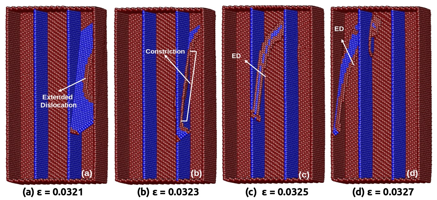
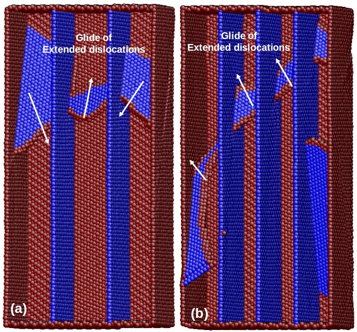
The deformation of Cu nanopillar with single and multiple twin boundaries has been investigated under compressive loading. As a representative one, the deformation behaviour of Cu nanopillar with two twin boundaries has been shown in Figure 6. It can be seen that the yielding in twinned nanopillars occurs through the nucleation of extended dislocation consisting of leading (1/6[12]) and trailing (1/6[121]) partials. Following yielding, the extended dislocation glides towards a nearby twin boundary as shown in Figure 6a. Since the presence of twin boundary restricts the free glide, the extended dislocation gets constricted and forms full dislocation at the twin boundary (Figure 6b) according to the following reaction:
| (1) |
This constricted full dislocation, which has high energy, cross-slips to neighbouring twinned grain on a plane symmetric to the original (symmetric slip transmission) by dissociating into an extended dislocation (Figure 6c). This dissociation can be written as
| (2) |
Here, the subscript ”T” for the leading and trailing partial indicates Burger’s vector in twinned grain. The extended dislocation again undergoes similar constriction and transmission upon facing the subsequent twin boundaries before annihilating at the free surface (Figure 6d).
In addition to symmetric slip transmission aided by the formation of constriction and dissociation, it has been observed that the extended dislocation can also cross-slip to twin boundary plane without forming any intermediate constriction (Figure 7). Initially, the glide of leading partial (part of an extended dislocation) is restricted at the twin boundary with trailing partial far behind (Figure 7a). This leading partial with Burger vector of 1/6[12] dissociates into a stair-rod dislocation (1/6[011]) and a Shockley partial dislocation 1/6[11] on the plane of the twin boundary (Figure 7b). In Burger vector terms, this dissociation can be written as
| (3) |
With increasing deformation, the trailing partial comes to the twin boundary and its interaction with existing stair-rod dislocation leads to the formation of Shockley partial lying on the twin boundary (Figure 7c). This reaction can be written as
| (4) |
Now, the two Shockley partials lying on the twin boundary ( and ), which are separated by a finite distance, constitutes an extended dislocation with a Burgers vector of 1/2[01 or CA, which also lies on twin boundary (Figure 7c). With increasing deformation, the incident extended dislocation completely cross-slips to the twin boundary plane and glides further on the same plane as shown in Figure 7d.
3.4 Deformation mechanisms in twinned 112 Cu nanopillars under tensile loading
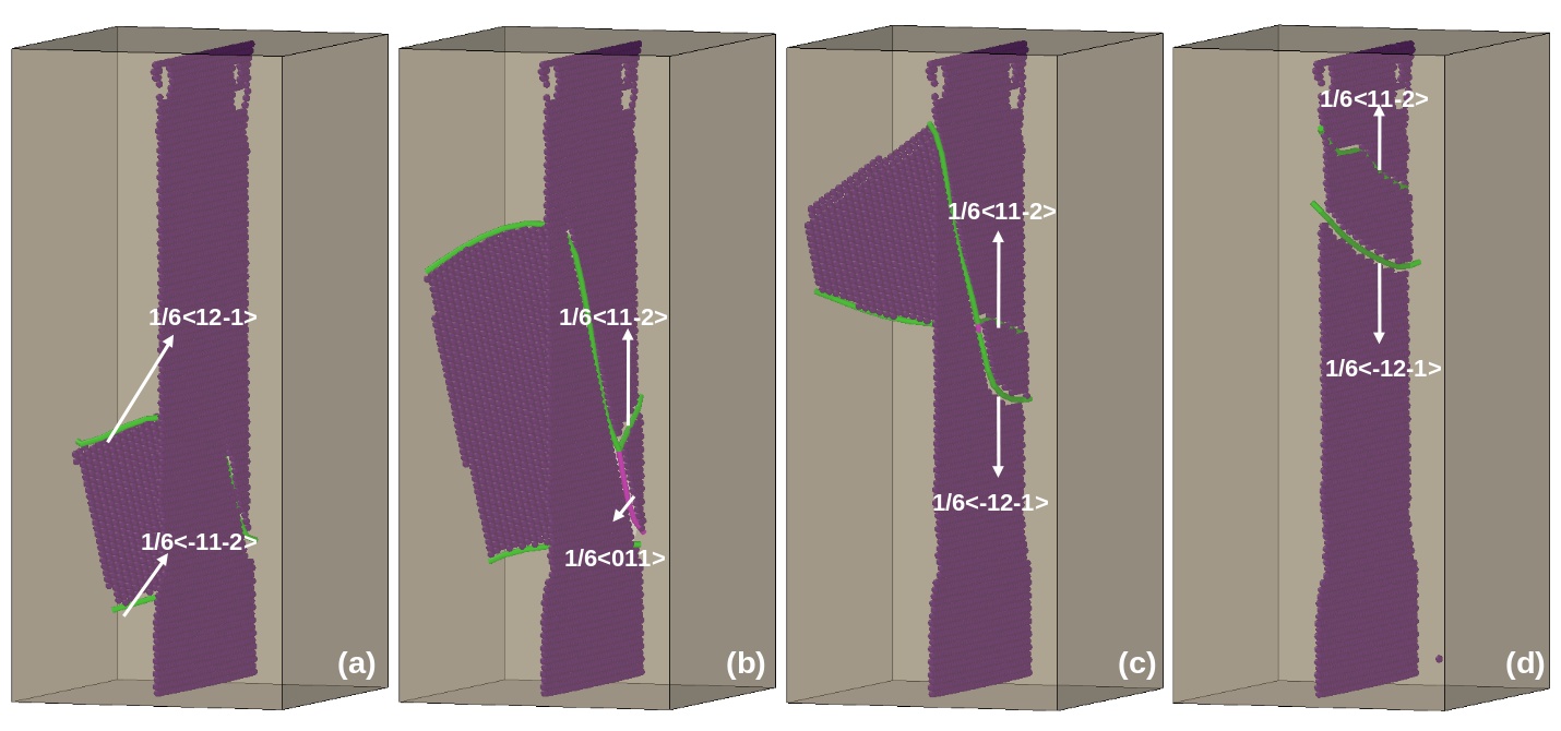
Like compressive loading, tensile deformation of nanopillars with single and multiple twin boundaries has been investigated. Figure 8 shows the atomic snapshots of twinned 112 Cu nanopillar containing a single twin boundary under tensile loading. The yielding in twinned nanopillar occurs through the nucleation of leading partial dislocations from two different corners of the nanopillar (Figure 8a). The two nucleated leading partials glide towards each other and interact at twin boundary resulting in the formation of a stair-rod dislocation (Figure 8b), which again lies on twin boundary plane. With increasing deformation, the stair-rod dislocation again dissociates into two trailing partials gliding on the same planes as that of the original leading partials (Figure 8c). The dissociation of stair-rod into two trailing partials annihilate the stacking faults produced by leading partials (Figure 8c). This novel mechanism of stair-rod formation and dissociation results in deformation proceeding through extended dislocations (leading followed by trailing) in twinned nanopillars as shown in Figure 8d. Similar formation of stair-rod and its dissociation at the twin boundary has been reported in earlier studies [13, 31].

In addition to stair-rod formation through two leading partials at the twin boundary, the stair-rod formation due to a single leading partial dislocation has also been observed as shown in Figure 9. Here, once the leading partial encounters the twin boundary (Figure 9a), it cross-slips to the next grain leaving behind a Hirth stair-rod dislocation at the twin boundary (Figure 9b) according to the following reaction,
| (5) |
With increasing strain, the Hirth dislocation on the twin boundary dissociates into two Shockley partial dislocations, one gliding back into the original grain and the other gliding behind the leading partial on the cross-slip plane (Figure 9b). This dissociation of Hirth dislocation can be written as
| (6) |
Here, it can be seen that these dissociated partials act as trailing dislocations making the deformation in nanopillars proceed through extended dislocations (Figure 9b-c). The Burgers vector of these extended dislocations is the summation of leading and trailing partials as shown below
| (7) |
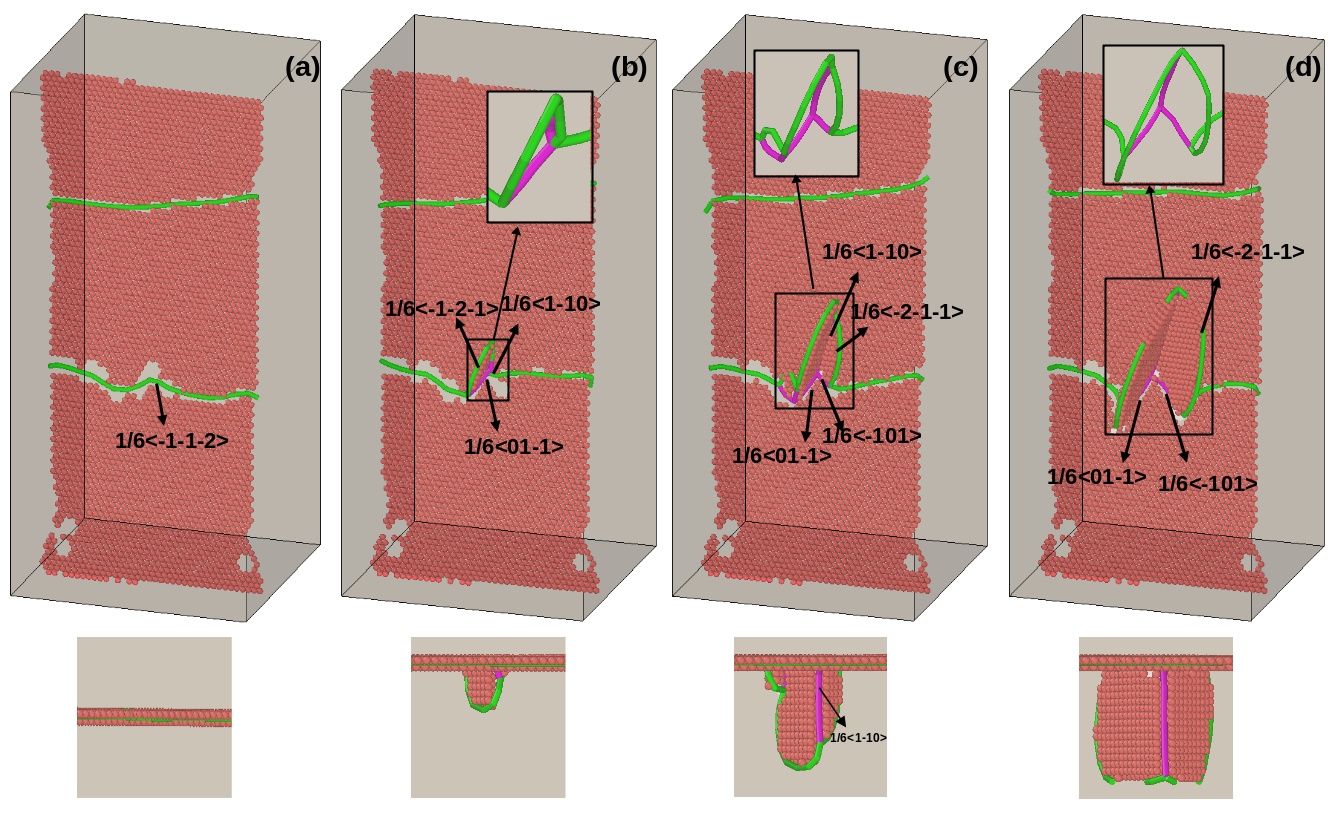
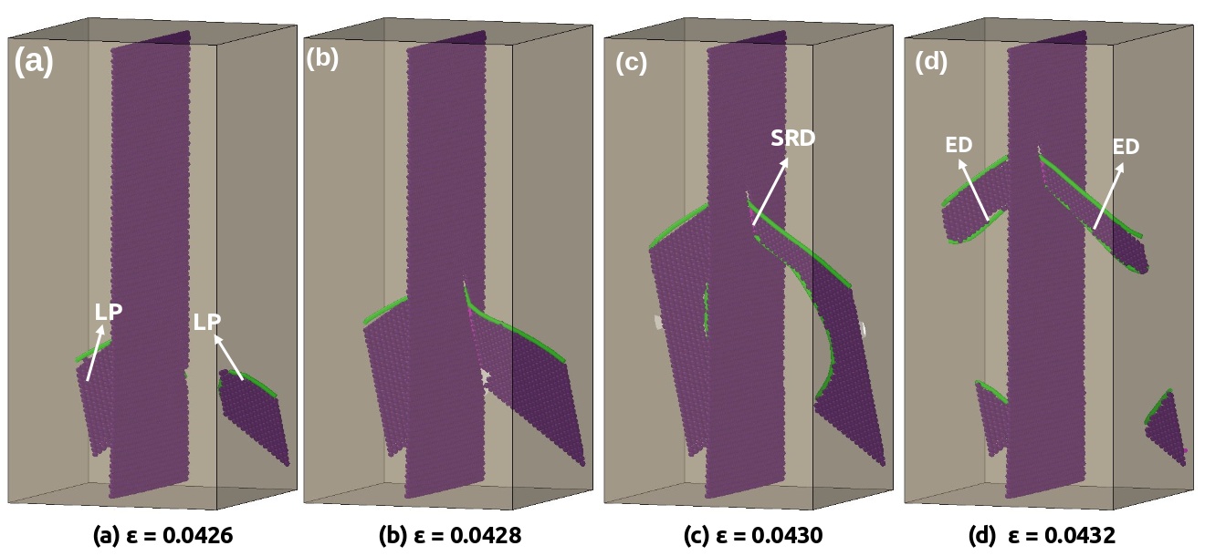
Similar to the cross-slip mechanism seen in compressive loading, it has been observed that under tensile loading also the extended dislocation can cross-slip to twin boundary plane. However, this cross-slip onto the twin boundary plane has been mediated by forming a constriction. Following the cross-slip, the extended dislocation lying on the twin boundary can be seen in Figure 10a. Interestingly, one partial of this extended dislocation gets dissociated into a stair-rod dislocation (which lies on the twin boundary) and a Shockley partial dislocation (which protruded out of the twin boundary) as shown in Figure 10b. This dissociation can be written as
| (8) |
Following this dissociation, the small segment of protruded Shockley partial dislocation again dissociates into a stair-rod dislocation and a Shockley partial dislocation as shown in Figure 10c. This dissociation in Burger’s vector terms can be written as
| (9) |
As the deformation proceeds, the length of both stair-rod dislocation and Shockley partial dislocation increases (Figure 10c). Then, a new stair-rod dislocation (which lies on the twin boundary) forms upon the interaction of dissociated Shockley partial and a Shockley partial lying on the twin boundary (Figure 10c). The formation of stair-rod occurs according to the following reaction:
| (10) |
Upon new stair-rod formation on the twin boundary, all dislocations (stair-rods and Shockley partials) lying on the twin boundary plane glide towards the surface (Figure 10d). Similarly, the protruded stair-rod and Shockley partial dislocations also move away from the twin boundary (Figure 10d).
Thus, the stair-rod formation due to two or one leading partials makes the deformation to proceed by extended dislocations under tensile loading. Likewise, Figure 11 shows the plastic deformation in nanopillar with multiple twin boundaries, which is also dominated by extended dislocations formed through similar mechanism of stair-rod formation and dissociation. Here, it is interesting to note that the plastic deformation in twinned nanopillars (which occurred through extended dislocations) is quite different from partial dislocation slip in perfect 112 nanopillars.
4 Discussion
4.1 Yield stress in twinned nanopillars
The results with respect to the strength of axially twinned Cu nanopillars indicate that, irrespective of twin boundary spacing, all the twinned nanopillars possess higher strength as compared to their perfect counterparts (Figure 3). Further, the yield strength decreases with increasing the twin boundary spacing. In orthogonally twinned nanopillars, the higher strength of twinned nanopillars has been attributed to different factors like redistribution of interior stress within the nanopillar [1] and strong repulsive force offered by twin boundaries on dislocations [32, 33, 34]. In axially twinned nanopillars also similar factors influence the yield strength.
In order to understand the role of stress redistribution in individual twinned regions, the strength of single crystal nanopillars with cross-section width (d) equal to the twin boundary spacing has been investigated. Figure 12a shows the variation of yield strength in perfect nanopillars as a function of cross-section width (d) (here d is equivalent to twin boundary spacing). For comparison, the strength of original perfect nanopillar (d = 10 nm) and twinned nanopillars of different twin boundary spacing has also been shown in Figure 12a. It can be seen that, the perfect nanopillars (of size equivalent to twin boundary spacing) exhibit an expected size effect i.e., strength decreases with increasing size [35]. Further, the yield strength of the twinned nanopillar is much lower than the yield strength of corresponding perfect nanopillar with size equal to twin boundary spacing. With this comparison, it can be concluded that the strength of individual twinned regions has some contribution in dictating the overall strength of the twinned nanopillars. However, it is not directly additive i.e., the sum of the yield strength of individual perfect nanopillars (of size equal to twin boundary spacing), is not equal to the strength of twinned nanopillar of same spacing. This may be attributed to the surface modification introduced due to the incorporation of twin boundaries from individual perfect nanopillars.
The other factor is the repulsive force acting on the dislocations due to twin boundaries [27, 32, 33, 34]. Deng and Sansoz [33] have shown that the repulsive force acting on the dislocations is proportional to the Burgers vector and inversely proportional to twin boundary spacing. Generally, the critical resolved shear stress (CRSS) for dislocation nucleation in twinned nanopillars () can be written as [36] , where is the CRSS in pure twin free nanopillar and is the additional contribution to CRSS due to the presence of twin boundaries. Here, is simply the product of yield stress and maximum value of Schmid factor in perfect nanopillars and the is given by Deng and Sansoz [33] as follows;
| (11) |
Here for Cu, is approximately 0.3 [33], the shear modulus () is 53.31 GPa, is the angle between the twin boundary and the {111} slip plane, is the Poisson’s ratio, is the Burgers vector of partial dislocations, is the twin boundary spacing, and is the size of the nanopillars. Based on this formulation and given parameters, the values of have been calculated for nanopillars with different twin boundary spacing in the range 1.6 - 5 nm. It has been observed that varies in the range 2.28 GPa (for nanopillar with = 1.6 nm) to 2.11 GPa (for nanopillar with = 5 nm). In other words, higher is the twin boundary spacing lower is the repulsive force and this leads to lower yield stress values. In nanopillars with smaller twin boundary spacing, the high repulsive force makes the dislocation nucleation and glide difficult, thus giving rise to increase in yield strength.
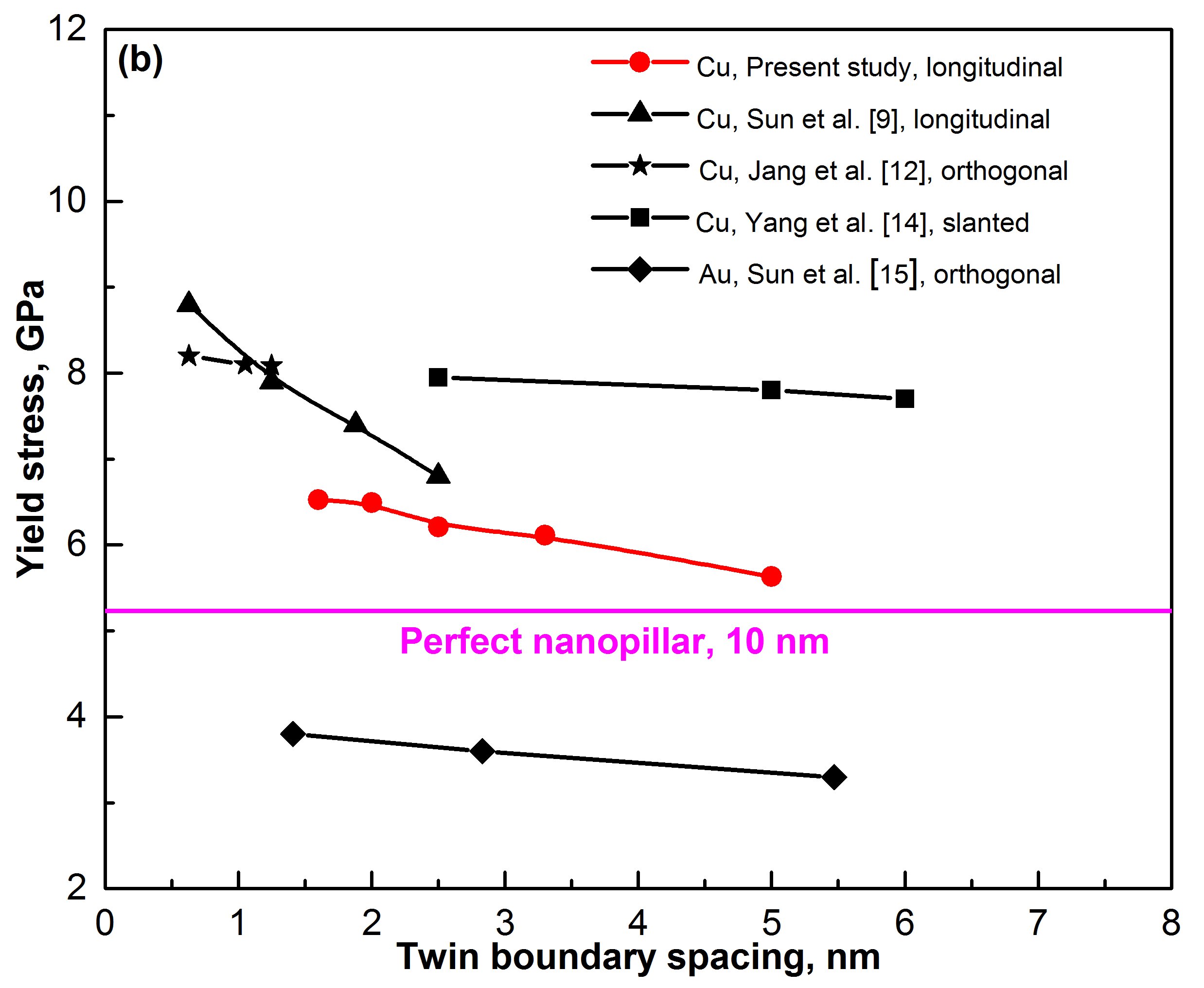
Figure 12b compares the yield stress values of twinned nanopillars in the present study with that reported in other studies in literature [9, 12, 14, 15]. Similar to the present study, many studies in the literature have reported that the yield stress decreases with increasing twin boundary spacing. However, the absolute values of yield stress are different in different studies. This difference in yield stress values may arise due to many factors like nanowire size, cross section shape and twin boundary orientation.
4.2 Deformation mechanisms and cross-slip
The results also indicate that the axial twin boundaries significantly influence the deformation mechanisms of Cu nanopillars. The deformation in perfect 112 nanopillars occurs by partial dislocation slip/twinning under tensile loading. Generally, in 112 oriented nanopillars, the deformation by partial dislocation slip is predicted according to Schmid factor analysis [29]. However, the introduction of twin boundaries changed the deformation mode from partial dislocation slip/twinning to extended dislocation slip. The extended dislocations in twinned nanopillars are facilitated by the stair-rod formation and its dissociation on the twin boundary. On the other hand, the deformation is dominated by the slip of extended dislocations under the compressive loading of perfect as well as twinned nanopillars, which is in agreement with Schmid factor based predictions [29]. This indicate that under compression, the deformation mechanisms are not influenced by the presence of twin boundaries.
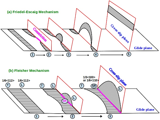
Irrespective of loading conditions, the presence of twin boundaries has introduced an extensive cross-slip of dislocations from one grain to the neighbouring grain and also the cross-slip onto the twin boundary plane. This indicates that the presence of twin boundaries significantly influences the deformation in FCC Cu nanopillars by the cross-slip activity. Since the deformation under compressive loading is dominated by extended dislocations, these extended dislocations get constricted at the twin boundary and results in formation of full dislocation (Figure 6). This constricted full dislocation, which has high energy, cross-slip to neighbouring grain on a plane symmetric to the original by dissociating into an extended dislocation (Figure 6). This mechanism is similar to the Friedel-Escaig (FE) [37, 38, 39] cross-slip mechanism as shown schematically in Figure 13a. The FE cross-slip mechanism involves the constriction of two partials in the initial glide plane followed by re-dissociation into the cross-slip plane (Figure 13a). In addition to FE mechanism, it has also been observed that the extended dislocation can also cross-slip to twin boundary plane without forming any constriction. As shown in Figure 7, the cross-slip of an extended dislocation is also facilitated by forming an intermediate stair-rod dislocation, which is similar to Fleischer mechanism of cross-slip in FCC metals [40] as shown schematically in Figure 13b. In Fleischer mechanism of cross-slip, the leading partial dissociates into a stair-rod and another Shockley partial on the cross-slip plane without the concept of constriction. In other words, the leading partial and stacking fault fold over from initial glide plane to cross-slip plane, by leaving a stair-rod dislocation at the intersection (Figure 13b). If the the glide plane and cross-slip plane are at an acute angle, then the low energy stair-rod (1/6110) forms at the intersection (Figure 7), while high energy Hirth stair-rod (1/3100) forms at obtuse intersection (Figure 9).
Similar to compressive loading, cross-slip through Fleischer mechanism has also been observed under tensile loading (Figure 9). However, the Friedel-Escaig mechanism of cross-slip has not been observed. This is mainly because the trailing partials under tensile loading are generated from the dissociation of stair-rod dislocation lying on the twin boundary. This restricts the probability of constriction of leading and trailing partials. Similar to that observed in the present study, Zhu et al. [41] have modeled the slip transfer reactions of screw dislocations in nanotwinned Cu bi-crystals and predicted the two different cross-slip mechanisms in accordance with Friedel-Escaig and Fleischer. Further, Fleischer mechanism was also observed in atomistic simulations of stress driven cross-slip in FCC Al [42].
The other interesting observation in the present study is the glide of partial/extended dislocation along the plane of twin boundary. Since the twin boundary is parallel to the loading direction, the shear stress acting on dislocations lying on this plane is zero. Therefore, the glide of any dislocations on the axial twin boundary is not expected. However, under both tensile and compressive loading, the frequent glide of partial/extended dislocations has been observed along this plane. An example of such glide can be seen from Figures 7c-d. Similar glide of partial dislocations migrating on the twin boundary has been reported by Jeon and Dehm [19]. This unusual glide may be due to the rotation of the sample under tensile/compressive loading or stress localization in the vicinity of twin boundaries.
Finally, it is important to mention that the twin boundary spacing considered in the present study is in the range 1.5 - 5 nm. This is in the same order of magnitude as that of the equilibrium spacing of the partial dislocations in Cu, which varies in the range 1.5 - 3 nm, depending on the size [43] and 2 - 5 nm depending on the dislocation orientation [44]. For a perfect nanowire of size 10 nm, the equilibrium spacing will be around 3 nm [43]. However, in the presence of twin boundaries, it may get reduced due to the repulsive force from twin boundaries. In this context, it is interesting to understand the relevance of this length scale to the observed deformation mechanisms, particularly the cross-slip. It is well known that the cross-slip mechanism strongly depends on the stacking fault energy (SFE) of the materials, which in turn is related to the equilibrium separation of partials. The dislocations easily cross-slips in materials with high SFE, while the cross-slip is difficult in low SFE materials. As the SFE is inversely proportional to equilibrium separation of partials, the extended dislocations having a wider partial separation finds it difficult to cross-slip, while cross-slip is easy for dislocations with smaller partial separation. Thus, it can be concluded that the length scale of the equilibrium separation of partial dislocations has some effect on the observed deformation mechanisms in the present study, particularly the cross-slip mechanism.
5 Conclusions
The role of twin boundaries on the strength and deformation mechanisms of perfect and twinned Cu nanopillars has been investigated under tensile and compressive loading by means of atomistic simulations. The simulation results indicated that the presence of twin boundaries strengthens the nanopillars. The yield strength in longitudinally or axially twinned nanopillars increases with decreasing twin boundary spacing, which is similar to that observed in orthogonally twinned nanopillars. This strengthening in twinned nanopillars may be attributed to repulsive force offered by twin boundaries on dislocations and stress redistribution in individual twinned regions. Further, the yield strength of twinned nanopillars show tension-compression asymmetry, which is higher than that exhibited by perfect nanopillars.
In addition to strength, the presence of twin boundaries also changes the operative deformation mechanisms as compared to perfect nanopillars. Under compressive loading, the deformation in 112 perfect as well as twinned nanopillars is dominated by the slip of extended dislocations. Further, the presence of twin boundaries under compressive loading introduces extensive cross-slip activity from one grain the other and also onto the twin boundary plane. This cross-slip activity under compressive loading occurs through two different mechanisms namely Friedel-Escaig mechanism and Fleischer mechanism. However, no cross-slip activity has been noticed in perfect nanopillars.
On the other hand, under tensile loading, the deformation in perfect nanopillars occurs by partial dislocation slip/twinning, which changes to extended dislocation activity following the introduction of twin boundaries. This change in twinned nanopillars is due to the formation and dissociation of a stair-rod dislocation on the twin boundary. This stair-rod dislocation, which forms through the interaction of two leading partials at the twin boundary, dissociates into two trailing partials gliding on the same plane as that of the leading partials, thus constituting an extended dislocation slip. This extended dislocations under tensile loading also exhibit cross-slip activity in twinned nanopillars. However, this cross-slip occurs only through Fleischer mechanism and no Friedel-Escaig mechanism of cross-slip has been observed under tensile loading. Further, the dislocation glide along the twin boundary has also been observed under tensile and compressive loading, despite zero resolved shear stress on the twin boundary plane.
References
- [1] A.J. Cao, Y.G. Wei, and S.X. Mao, Deformation mechanisms of face-centered-cubic metal nanowires with twin boundaries, Appl.Phys. Lett. 90 (2007), p. 151909.
- [2] L. Lu and X. Chen, Revealing the maximum strength in nanotwinned copper, Science 323 (2009), pp. 607-610.
- [3] L. Liu, J. Wang, S.K. Gong, and S.X. Mao, Atomistic observation of a crack tip approaching coherent twin boundaries, Sci. Rep. 4 (2014), p. 4397.
- [4] C. Deng and F. Sansoz, Effects of twin and surface facet on strain-rate sensitivity of gold nanowires at different temperatures, Phys. Rev. B 81 (2010), p. 155430.
- [5] J. Sun, L. Fang, K. Sun, and J. Han, Direct observation of dislocations originating from perfect twin boundaries, Scr. Mater. 65 (2011), pp. 501-504.
- [6] C. Deng and F. Sansoz, Size-dependent yield stress in twinned gold nanowires mediated by site-specific surface dislocation emission, Appl. Phys. Lett. 95 (2009), p. 091914.
- [7] Y. Zhang and H. Huang, Do twin boundaries always strengthen metal nanowires?, Nano Res. Lett. 4 (2009), p. 34.
- [8] Y.T. Zhu, X.L. Wu, X.Z. Liao, J. Narayan, L.J. Kecskes, and S.N. Mathaudhu, Dislocation-twin interactions in nanocrystalline fcc metals, Acta Mater. 59 (2011), pp. 812-821.
- [9] J. Sun, C. Li, J. Han, X. Shao, X. Yang, H. Liu, D. Song, and A. Ma, Size effect and deformation mechanism in twinned copper nanowires, Metals 7 (2017), p. 438.
- [10] J. Wang and H. Huang, Novel deformation mechanism of twinned nanowires, Appl. Phys. Lett. 88 (2006), p. 203112.
- [11] Y.B. Wang and M.L. Sui, Atomic-scale in situ observation of lattice dislocations passing through twin boundaries, Appl. Phys. Lett. 94 (2009), p. 021909.
- [12] D. Jang, X. Li, H. Gao, and J.R. Greer, Deformation mechanisms in nanotwinned metal nanopillars, Nat. Nanotechnol. 7 (2012), pp. 594-601.
- [13] G. Sainath and B.K. Choudhary, Molecular dynamics simulation of twin boundary effect on deformation of Cu nanopillars, Phys. Lett. A 379 (2015), pp. 1902-1905.
- [14] Z. Yang, L. Zheng, Y. Yue, and Z. Lu, Effects of twin orientation and spacing on the mechanical properties of Cu nanowires, Sci. Rep. 7 (2017), p. 10056.
- [15] J. Sun, J. Han, Z. Yang, H. Liu, D. Song, A. Ma, and L. Fang, Rebuilding the strain hardening at a large strain in twinned Au nanowires, Nanomater. 8 (2018), p. e848.
- [16] K.A. Afanasyev and F. Sansoz, Strengthening in gold nanopillars with nanoscale twins, Nano Lett. 7 (2007), pp. 2056-2062.
- [17] F. Hammami and Y. Kulkarni, Size effects in twinned nanopillars, J. Appl. Phys. 116 (2014), p. 033512.
- [18] B. Roos, B. Kapelle, G. Richter, and C.A. Volkert, Surface dislocation nucleation controlled deformation of Au nanowires, Appl. Phys. Lett. 105 (2014), p. 201908.
- [19] J.B. Jeon and G. Dehm, Formation of dislocation networks in a coherent Cu 3(111) twin boundary, Scr. Mater. 102 (2015), pp. 71-74.
- [20] G. Cheng, S. Yin, T.-H. Chang, G. Richter, H. Gao, and Y. Zhu, Anomalous tensile detwinning in twinned nanowires, Phys. Rev. Lett. 119 (2017), p. 256101.
- [21] S. Plimpton, Fast parallel algorithms for short-range molecular dynamics, J. Comp. Phy. 117 (1995), pp. 1-19.
- [22] Y.Mishin, M.J. Mehl, D.A. Papaconstantopoulos, A.F. Voter, and J.D. Kress, Structural stability and lattice defects in copper: Ab initio, tight-binding, and embedded-atom calculations, Phys. Rev. B, 63 (2001), p. 224106.
- [23] W. Liang and M. Zhou, Atomistic simulations reveal shape memory of fcc metal nanowires, Phys. Rev. B 73 (2006), p. 115409.
- [24] J. Li, AtomEye: an efficient atomistic configuration viewer, Modell. Simul. Mater. Sci. Eng. 11 (2003), pp. 173-177.
- [25] A. Stukowski, Visualization and analysis of atomistic simulation data with OVITO-the Open Visualization Tool, Modell. Simul. Mater. Sci. Eng. 18 (2009), p. 015012.
- [26] A. Stukowski and K. Albe, Dislocation detection algorithm for atomistic simulations, Model. Simul. Mater. Sci. Eng. 18 (2010), p. 025016.
- [27] G. Sainath and B. K. Choudhary, Deformation behaviour of body centered cubic iron nanopillars containing coherent twin boundaries, Philos. Mag. 96 (2016), pp. 3502-3523.
- [28] J.A. Zimmerman, E.B. Webb, J.J. Hoyt, R.E. Jones, P.A. Klein, and D.J. Bammann, Calculation of stress in atomistic simulations, Modell. Simul. Mater. Sci. Eng. 12 (2004), pp. S319-S322.
- [29] P. Rohith, G. Sainath, and B.K. Choudhary, Effect of orientation and mode of loading on deformation behaviour of Cu nanowires, Comp. Condens. Mat. 17 (2018), p. e00330.
- [30] I. Salehinia and D.F. Bahr, Crystal orientation effect on dislocation nucleation and multiplication in FCC single crystal under uniaxial loading, Inter. J. Plast. 52 (2014), pp. 133-146.
- [31] Y. Zhang, S. Jiang X. Zhu, and Y. Zhao, Dislocation mechanism of void growth at twin boundary of nanotwinned nickel based on molecular dynamics simulation, Phy. Lett. A 380 (2016), pp. 2757-2761.
- [32] Z. Chen, Z. Jin, and H. Gao, Repulsive force between screw dislocation and coherent twin boundary in aluminum and copper, Phys. Rev. B 75 (2007), p. 212104.
- [33] C. Deng and F. Sansoz, Repulsive force of twin boundary on curved dislocations and its role on the yielding of twinned nanowires, Scr. Mater. 63 (2010), pp. 50-53.
- [34] X. Guo and Y. Xia, Repulsive force vs. source number: Competing mechanisms in the yield of twinned gold nanowires of finite length, Acta Mater. 59 (2011), pp. 2350-2357.
- [35] G. Sainath, P. Rohith, and B.K. Choudhary, Size dependent deformation behaviour and dislocation mechanisms in 100 Cu nanowires, Philos. Mag. 97 (2017), pp. 2632-2657.
- [36] L. Hao, Q. Liu, Y. Fang, M. Huang, W. Li, Y. Lu, J. Luo, P. Guan, Z. Zhang, L. Wang, X. Han, Mechanical behavior of metallic nanowires with twin boundaries parallel to loading axis, Comp. Mater. Sci. 169 (2019), p. 109087.
- [37] J. Friedel, in Dislocations and mechanical properties of crystals, Wiley, New York (1957) 330.
- [38] J. Friedel, Dislocations, Pergamon, New York 274 (1964).
- [39] B. Escaig, Cross-slip of screw dislocations in F.C.C. structures, J. Phys. France 29 (1968), pp. 225-239.
- [40] R.L. Fleischer, Cross slip of extended dislocations, Acta. Mater. 7 (1959), pp. 134-135.
- [41] T. Zhu, J. Li, A. Samanta, H.G. Kim, and S. Suresh, Interfacial plasticity governs strain rate sensitivity and ductility in nanostructured metals, Proc. Natl. Acad. Sci. 104 (2007), pp. 3031-3036.
- [42] T. Vegge, T. Rasmussen, T. Leffers, O.B. Pedersen, and K.W. Jacobsen, Determination of the of rate cross slip of screw dislocations, Phys. Rev. Lett. 85 (2000), p. 3866.
- [43] P. Rohith, G. Sainath and B. K. Choudhary, Dependence of equilibrium stacking fault width on thickness of Cu thin films : A molecular dynamics study, AIP Conf. Proc. 1832 (2017), p. 080060-1.
- [44] D.J.H. Cockayne, M.L. Jenkins, and I.L.F. Ray, The measurement of stacking-fault energies of pure face-centred cubic metals, Philos. Mag. 24 (1971), pp. 1383-1392.