Onset of a skyrmion phase by chemical substitution in MnGe chiral magnet
Abstract
We study the evolution of the magnetic phase diagram of Mn1-xFexGe alloys with concentration () by small-angle neutron scattering. We unambiguously observe the absence of a skyrmion lattice (or A-phase) in bulk MnGe and its onset under a small Mn/Fe substitution. The A-phase is there endowed with an exceptional skyrmion density, and is stabilized within a very large temperature region and a field range which scales with the Fe concentration. Our findings highlight the possibility to fine-tune properties of skyrmion lattices by means of chemical doping.
Introduction. The incommensurate magnetic orderings of alloys with B20 structure, such as MnSi or FeGe, have received an increasing attention in the last decade due to their peculiar magneto-transport properties. Their helical spin structure results from a competition between ferromagnetic (FM) exchange and antisymmetric Dzyaloshinskii-Moriya interaction (DMI), allowed by the lack of inversion symmetry in the crystal structure Ishikawa et al. (1976); Lebech et al. (1989); Nakanishi et al. (1980); Bak and Jensen (1980). The presence of helical Bragg peaks in the direction perpendicular to the applied field , initially discovered in bulk MnSi single crystal by small-angle neutron scattering (SANS) Lebech et al. (1995); Grigoriev et al. (2006) was later on ascribed to a stacking of two-dimensional lattice of magnetic defects called ”skyrmions” (SK) Mühlbauer et al. (2009). The SK lattice, an hexagonal pattern with wavevector , was further observed in real space by Lorentz transmission electron microscopy (TEM) Yu et al. (2010). Recent theories show that it results from uniaxial anisotropy, due to DMI in bulk or interfaces in layers, both reducing the effective symmetry Rybakov et al. (2015). In the bulk, a stable SK lattice is actually only observed in a limited (H,T) region just below the ordering temperature , the so-called ”A-phase”. This suggests that chiral fluctuations, numerous around Grigoriev et al. (2005, 2011); Janoschek et al. (2013), are needed for its stabilization together with the DMI term.
In the B20 family, MnGe helical magnet synthesized in metastable form under high pressure and temperature Tsvyashchenko et al. (2012), stands as an exception. MnGe orders at high temperature (TC 170 K,) with much shorter helical wavelength ( 2-3 nm) Makarova et al. (2012); Kanazawa et al. (2011) than MnSi or FeGe. This strongly suggests that sizable next-nearest antiferromagnetic (AFM) interactions are responsible for the helical structure Chizhikov and Dmitrienko (2013); Altynbaev et al. (2016a). MnGe also exhibits a magnetic order-disorder transition spanning a large temperature range Altynbaev et al. (2014), and involving low-energy spin fluctuations Martin et al. (2016, 2019). In MnGe, the SK lattice remains elusive Kanazawa et al. (2012) and exotic monopole defects have been further proposed Kanazawa et al. (2016).
Remarkably, ab initio calculations show that the DMI term is close to zero in MnGe, and increases under Mn/Fe substitution Gayles et al. (2015); Koretsune et al. (2018). In Mn1-xFexGe compounds, the ground state helical structure remains essentially similar up to x=0.35 Grigoriev et al. (2013), but the borders of the A-phase have not yet been directly observed. Therefore, the Mn-rich Mn1-xFexGe compounds are of a great interest to study the influence of the DMI term on the stability of the SK lattice.
In this Letter, we present a comprehensive SANS study of the magnetic structure of Mn1-xFexGe compounds with under an applied magnetic field. We have used the same protocol for all samples, a well-defined procedure allowing one to determine the boundaries of the A-phase without ambiguity. We find that pure MnGe does not show any traces of a SK lattice within the explored temperature () and field () ranges. An increase of Fe concentration, , results in the appearance of the A-phase with the shortest period ever observed. This phase extends over a wide temperature range, almost independent of , whereas its field range increases with . The latter scales with the calculated DMI term. Our finding agree with theoretical calculation of an almost zero DMI term in MnGe, and support the A-phase as an inherent feature of DMI helimagnets.
Experimental results. Polycrystalline Mn1-xFexGe samples were previously used in Ref. Altynbaev et al., 2016a. Details on their synthesis are given in the Supplementary Material SM . SANS experiments were carried out on the SANS-1 instrument at the Heinz Maier-Leibnitz Institute (MLZ, Garching, Germany Heinemann and Mühlbauer (2015)) and on the PA20 instrument at the Laboratoire Léon Brillouin, (LLB, Saclay, France Chaboussant et al. (2012)), covering momentum transfers in the range nm-1. The scattered intensity was systematically measured after zero-field cooling from K (in the paramagnetic state) down to the chosen temperature, and upon a gradual increase of the magnetic field up to 9 T.
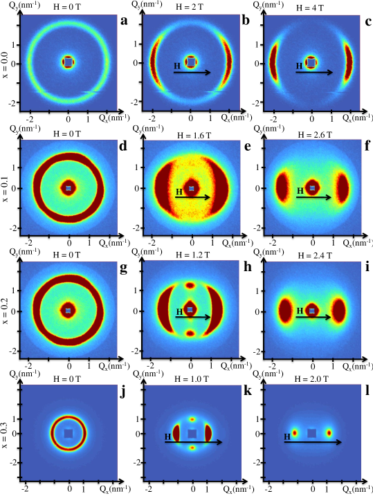
Fig. 1 shows examples of SANS maps taken at different fields at K on Mn1-xFexGe compounds. In pure MnGe (Figs. 1 a-c), the isotropic ring observed in zero field transforms into a moon-like pattern oriented along the field, as expected from the evolution of the helical structure towards the conical one. However, we do not observe peaks in the direction perpendicular to the field, whatever the field and temperature up to 9 T and 200 K. The latter are the usual hallmark of the A-phase, within which the longitudinal magnetization is modulated in the form of a SK lattice. Strikingly, they appear in the substituted samples starting from the lowest concentration , as a weak signal superimposed on the ring structure (Fig. 1 d-f). The spots from the A-phase become better-defined for the samples with = and (Fig. 1 g-i and j-l, respectively). They directly demonstrate the transition of part of the samples into the A-phase and the emergence of SK lattices.
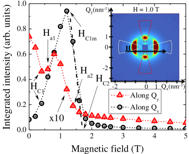
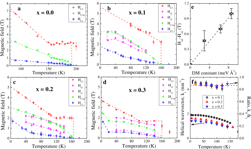
In order to determine the (H,T) phase diagrams of the studied samples, the neutron scattering intensities were integrated in the horizontal or vertical directions over the azimuthal angle of , i.e. longitudinal or transverse to the applied field, respectively. From the field-dependence of the intensity at a given temperature, up to five characteristic fields can be deduced, as shown in Fig. 2 for = 0.3 at K. The critical field , which we consider as the field value where the longitudinal and transverse intensities differ by more than 20%, indicates the departure from the multi-domain helical state. The field where the longitudinal intensity reaches its maximum, marks the end of this reorientation process and the transition of each sample grain into a single domain conical state. The critical field , determined by extrapolating to zero the linear decay of the longitudinal intensity with the field increase above , marks the transition from the conical to the field-induced ferromagnetic state. The fields and are determined as the borders of the field range where the intensity in the direction, transverse to the external field, increases, indicating the SK peaks to emerge from the ring-like signal. These fields correspond to the lower and upper limit of the A-phase, respectively. Details on the accurate determination of the values of and are given in the Supplementary Material SM . The resulting (H,T) phase diagrams are shown in Fig. 3a for MnGe and Fig. 3b-d for the substituted compounds.
In Fig. 3e, we plot the quantity which marks the field-extension of the A-phase for each concentration versus the DMI constant deduced from ab-initio calculations. The error bars on take into account its temperature dependence, whereas the DMI constant is averaged over several theoretical works Gayles et al. (2015); Kikuchi et al. (2016); Mankovsky et al. (2018). Both quantities have negligible values for pure MnGe, and are linearly increasing with concentration within error bars.
The positions of the Bragg reflections yield the periodicity of the helical structure and of the SK lattice. They can be determined for each sample as a function of field and temperature. The wavevectors of the helical structure () and SK lattice () are almost independent of the applied field. They slowly increase with decreasing temperature, in the same way for each sample (Fig. 3f). Strikingly, their ratio (/) remains almost constant, independent of the temperature and sample considered, close to the value .
Discussion. In pure MnGe, the critical fields measured at low temperature and are the highest measured in B20 compounds so far. Upon heating, they decrease to zero at (Fig. 3a). As a main result, we find no traces of the SK lattice when performing a careful search in the whole (H,T) range up to 9 T and 200 K. The critical field decreases linearly upon heating down to 3 T at , then saturates and remains constant up to 190 K. As long as the traces of the helical structure persist up to 190 K the temperature range 150 K-190 K likely consists of a mixed state where helical fluctuations and ferromagnetic nano-regions coexist in the sample Altynbaev et al. (2014).
In the substituted compounds Mn1-xFexGe with , 0.2 and 0.3 (Fig. 3b-d), the temperature variation of the critical fields , and is similar to that of MnGe. and are almost independent of and decrease to zero at K. The main difference with MnGe is the occurrence of a A-phase in a wide (T, H) range. It is observed for 20 K K () and 40 K K (for ). The A-phase extends widely in the oriented helical-phase, between and (), or slightly above (=0.3). The large extension of the A-phase with temperature likely result from the intrinsic instability of MnGe Deutsch et al. (2014); Altynbaev et al. (2014); Martin et al. (2016) and Mn1-xFexGe Altynbaev et al. (2016b, a), favoring helical fluctuations well below the ordering temperature. Strikingly, in these Mn-rich compounds where the temperature extension of the A-phase does not depend much of , its field extension increases with , in a linear way (within error bars), as does the calculated DMI constant Gayles et al. (2015); Kikuchi et al. (2016); Mankovsky et al. (2018). The proportional increase of these two quantities (Fig. 3e) supports the DMI as the fundamental interaction needed to stabilize the A-phase in bulk B20 magnets.
The difference between the wavevectors of the helical structure and SK lattice is surprising. It means that the period of the SK is bigger than the period of the helical structure by almost 15% whatever the concentration and temperature. We should also note that simple geometric arguments in case of the hexagonal SK lattice imply an opposite ratio, namely Grigoriev et al. (2014). However, it is found experimentally that within 1-2%, either in bulk Lebech et al. (1995); Grigoriev et al. (2006); Ishimoto et al. (1990) or in two-dimensional Yu et al. (2010); Tonomura et al. (2012) helimagnets, with the exception of the frustrated disordered Co-Zn-Mn alloys Karube et al. (2016). Nevertheless, the observed ratio between and could suggest that the SKs found within the A-phase of Mn1-xFexGe () are not packed in a regular hexagonal fashion. We thus speculate that the observed difference might be related to the competition between FM and AFM exchange interactions or to chemical disorder (or both). This point deserves further theoretical and experimental studies.
The absence of a regular SK lattice in bulk MnGe suggests to reinterpret the first investigations of its (H,T) phase diagram. In the initial SANS experiments of Kanazawa et al. Kanazawa et al. (2012), the intensity peak attributed to the A-phase was observed after the application of a large field, that could orient not only the magnetic but also the crystal domains along the field direction. Therefore an alternative scenario involving helices blocked in the hard directions could explain such intensity. Observations of the SK lattice by TEM Tanigaki et al. (2015) may be impacted by multidomain structure or surface anisotropy. On the other hand, the absence of the SK lattice in bulk MnGe is fairly natural from a theoretical viewpoint, taking into account the vanishingly small value of its DM-constant. The question that remains open concerns the origin of the large topological Hall-effect (THE). Besides SK’s, other topological objects have been proposed in MnGe, such as monopole Kanazawa et al. (2016) or solitons defects Martin et al. (2019), owing to its intrinsic instability Deutsch et al. (2014); Altynbaev et al. (2014); Martin et al. (2016). They may provide another source for the THE.
Conclusion. We have observed the absence of a regular SK lattice or A-phase in MnGe and its onset under a small substitution of Mn for Fe. The A-phase is observed over a wide temperature range, thanks to the inherent fluctuations and metastable character of MnGe. Its field range increases linearly with the Fe concentration and calculated DMI-constant. These results emphasize that DMI and helical fluctuations are the main ingredients for the stabilization of a SK lattice in B20 magnets, and indicate a way to fine-tune the properties of dense SK lattice using controlled chemical substitution.
Acknowledgements. E.A., A.T. and S.G. are grateful to the Russian Scientific Foundation (Grant No. 17-12-01050).
References
- Ishikawa et al. (1976) Y. Ishikawa, K. Tajima, D. Bloch, and M. Roth, Solid State Communications 19, 525 (1976).
- Lebech et al. (1989) B. Lebech, J. Bernhard, and T. Freltoft, Journal of Physics: Condensed Matter 1, 6105 (1989).
- Nakanishi et al. (1980) O. Nakanishi, A. Yanase, A. Hasegawa, and M. Kataoka, Solid State Communications 35, 995 (1980).
- Bak and Jensen (1980) P. Bak and M. H. Jensen, J. Phys. C: Sol. St. Phys. 13, L881 (1980).
- Lebech et al. (1995) B. Lebech, P. Harris, J. S. Pedersen, K. Mortensen, C. Gregory, N. Bernhoeft, M. Jermy, and S. Brown, Journal of Magnetism and Magnetic Materials 140-144, 119 (1995).
- Grigoriev et al. (2006) S. V. Grigoriev, S. V. Maleyev, A. I. Okorokov, Y. O. Chetverikov, and H. Eckerlebe, Phys. Rev. B 73, 224440 (2006).
- Mühlbauer et al. (2009) S. Mühlbauer, B. Binz, F. Jonietz, C. Pfleiderer, A. Rosch, A. Neubauer, R. Georgii, and P. Böni, Science 323, 915 (2009).
- Yu et al. (2010) X. Z. Yu, Y. Onose, N. Kanazawa, J. H. Park, J. H. Han, Y. Matsui, N. Nagaosa, and Y. Tokura, Nature 465, 901 (2010).
- Rybakov et al. (2015) F. N. Rybakov, A. B. Borisov, S. Blügel, and N. S. Kiselev, Phys. Rev. Lett. 115, 117201 (2015).
- Grigoriev et al. (2005) S. V. Grigoriev, S. V. Maleyev, A. I. Okorokov, Y. O. Chetverikov, R. Georgii, P. Böni, D. Lamago, H. Eckerlebe, and K. Pranzas, Phys. Rev. B 72, 134420 (2005).
- Grigoriev et al. (2011) S. V. Grigoriev, E. V. Moskvin, V. A. Dyadkin, D. Lamago, T. Wolf, H. Eckerlebe, and S. V. Maleyev, Phys. Rev. B 83, 224411 (2011).
- Janoschek et al. (2013) M. Janoschek, M. Garst, A. Bauer, P. Krautscheid, R. Georgii, P. Böni, and C. Pfleiderer, Phys. Rev. B 87, 134407 (2013).
- Tsvyashchenko et al. (2012) A. Tsvyashchenko, V. Sidorov, L. Fomicheva, V. Krasnorussky, R. Sadykov, J. Thompson, K. Gofryk, F. Ronning, and V. Ivanov, in Magnetism and Magnetic Materials V (2012), vol. 190 of Solid State Phenomena, pp. 225–228.
- Makarova et al. (2012) O. L. Makarova, A. V. Tsvyashchenko, G. Andre, F. Porcher, L. N. Fomicheva, N. Rey, and I. Mirebeau, Phys. Rev. B 85, 205205 (2012).
- Kanazawa et al. (2011) N. Kanazawa, Y. Onose, T. Arima, D. Okuyama, K. Ohoyama, S. Wakimoto, K. Kakurai, S. Ishiwata, and Y. Tokura, Phys. Rev. Lett. 106, 156603 (2011).
- Chizhikov and Dmitrienko (2013) V. A. Chizhikov and V. E. Dmitrienko, Phys. Rev. B 88, 214402 (2013).
- Altynbaev et al. (2016a) E. Altynbaev, S.-A. Siegfried, E. Moskvin, D. Menzel, C. Dewhurst, A. Heinemann, A. Feoktystov, L. Fomicheva, A. Tsvyashchenko, and S. Grigoriev, Phys. Rev. B 94, 174403 (2016a).
- Altynbaev et al. (2014) E. Altynbaev, S.-A. Siegfried, V. Dyadkin, E. Moskvin, D. Menzel, A. Heinemann, C. Dewhurst, L. Fomicheva, A. Tsvyashchenko, and S. Grigoriev, Phys. Rev. B 90, 174420 (2014).
- Martin et al. (2016) N. Martin, M. Deutsch, F. Bert, D. Andreica, A. Amato, P. Bonfà, R. De Renzi, U. K. Rößler, P. Bonville, L. N. Fomicheva, et al., Phys. Rev. B 93, 174405 (2016).
- Martin et al. (2019) N. Martin, I. Mirebeau, C. Franz, G. Chaboussant, L. N. Fomicheva, and A. V. Tsvyashchenko, Phys. Rev. B 99, 100402 (2019).
- Kanazawa et al. (2012) N. Kanazawa, J.-H. Kim, D. S. Inosov, J. S. White, N. Egetenmeyer, J. L. Gavilano, S. Ishiwata, Y. Onose, T. Arima, B. Keimer, et al., Phys. Rev. B 86, 134425 (2012).
- Kanazawa et al. (2016) N. Kanazawa, Y. Nii, X. X. Zhang, A. S. Mishchenko, G. De Filippis, F. Kagawa, Y. Iwasa, N. Nagaosa, and Y. Tokura, Nature Communications 7, 11622 (2016).
- Gayles et al. (2015) J. Gayles, F. Freimuth, T. Schena, G. Lani, P. Mavropoulos, R. A. Duine, S. Blügel, J. Sinova, and Y. Mokrousov, Phys. Rev. Lett. 115, 036602 (2015).
- Koretsune et al. (2018) T. Koretsune, T. Kikuchi, and R. Arita, Journal of the Physical Society of Japan 87, 041011 (2018).
- Grigoriev et al. (2013) S. V. Grigoriev, N. M. Potapova, S.-A. Siegfried, V. A. Dyadkin, E. V. Moskvin, V. Dmitriev, D. Menzel, C. D. Dewhurst, D. Chernyshov, R. A. Sadykov, et al., Phys. Rev. Lett. 110, 207201 (2013).
- Kikuchi et al. (2016) T. Kikuchi, T. Koretsune, R. Arita, and G. Tatara, Phys. Rev. Lett. 116, 247201 (2016).
- Mankovsky et al. (2018) S. Mankovsky, S. Wimmer, S. Polesya, and H. Ebert, Phys. Rev. B 97, 024403 (2018).
- (28) See Supplemental Material at [url] for details about the samples and the analysis strategies used in this study, which includes Refs. [xx-yy].
- Heinemann and Mühlbauer (2015) A. Heinemann and S. Mühlbauer, Journal of large-scale research facilities 1, A10 (2015).
- Chaboussant et al. (2012) G. Chaboussant, S. Désert, P. Lavie, and A. Brûlet, J. Phys.: Conf. Series 340, 012002 (2012).
- Deutsch et al. (2014) M. Deutsch, P. Bonville, A. V. Tsvyashchenko, L. N. Fomicheva, F. Porcher, F. Damay, S. Petit, and I. Mirebeau, Phys. Rev. B 90, 144401 (2014).
- Altynbaev et al. (2016b) E. V. Altynbaev, A. S. Sukhanov, S.-A. Siegfried, V. A. Dyadkin, E. V. Moskvin, D. Menzel, A. Heinemann, A. Schreyer, L. N. Fomicheva, A. V. Tsvyashenko, et al., Journal of Surface Investigation. X-ray, Synchrotron and Neutron Techniques 10, 777 (2016b).
- Grigoriev et al. (2014) S. V. Grigoriev, N. M. Potapova, E. V. Moskvin, V. A. Dyadkin, C. Dewhurst, and S. V. Maleyev, JETP Letters 100, 216 (2014).
- Ishimoto et al. (1990) K. Ishimoto, H. Yamauchi, Y. Yamaguchi, J. Suzuki, M. Arai, M. Furusaka, and Y. Endoh, Journal of Magnetism and Magnetic Materials 90-91, 163 (1990).
- Tonomura et al. (2012) A. Tonomura, X. Yu, K. Yanagisawa, T. Matsuda, Y. Onose, N. Kanazawa, H. S. Park, and Y. Tokura, Nano Letters 12, 1673 (2012).
- Karube et al. (2016) K. Karube, J. S. White, N. Reynolds, J. L. Gavilano, H. Oike, A. Kikkawa, F. Kagawa, Y. Tokunaga, H. M. Rønnow, Y. Tokura, et al., Nature Materials 15, 1237 (2016).
- Tanigaki et al. (2015) T. Tanigaki, K. Shibata, N. Kanazawa, X. Yu, Y. Onose, H. S. Park, D. Shindo, and Y. Tokura, Nano Letters 15, 5438 (2015).