Dirac-vortex topological cavity
Abstract
Cavity design is crucial for single-mode semiconductor lasers such as the distributed feedback (DFB) and vertical-cavity surface-emitting lasers (VCSEL). By recognizing that both optical resonators feature a single mid-gap mode localized at the topological defect in a one-dimensional (1D) lattice, we generalize the topological cavity design into 2D using a honeycomb photonic crystal with a vortex Dirac mass — the analog of Jackiw-Rossi zero modes. We theoretically predict and experimentally demonstrate that such a Dirac-vortex cavity can have a tunable mode area across a few orders of magnitudes, arbitrary mode degeneracy, robustly large free-spectral-range, vector-beam output of low divergence, and compatibility with high-index substrates. This topological cavity could enable photonic crystal surface-emitting lasers (PCSEL) with stabler single-mode operation.
Single-mode diode lasers Chuang (2009) are the standard light sources for numerous applications, in which the single-modeness relies on the cavity design with subwavelength features. In long-haul fiber networks, the most widely used DFB laser Kogelnik and Shank (1971) (Table 1) of a uniform Bragg grating have two competing band-edge modes. Although the mode selection could be done with a certain yield by facet cleaving, a much stabler cavity design is to introduce a quarter-wavelength shift Haus and Shank (1976); Sekartedjo et al. (1984), so that a single mid-gap mode can lase at the Bragg frequency. The same 1D mid-gap defect state is also adopted for VCSELs Chuang (2009) to select a single longitudinal mode, used in local communications, computer mice, laser printers and face recognitions. In 2D Wang and Sheem (1973); Imada et al. (1999), the PCSEL (Table 1) has recently been commercialized HAM (2018) for its higher power and higher brightness Matsubara et al. (2008); Hirose et al. (2014); Yoshida et al. (2019). However, PCSELs again have at least two high quality-factor (Q) band-edge modes competing for lasing. It is obviously important to have a 2D cavity of a single robust mid-gap mode, which has been lacking since the notion of 2D DBFs Wang and Sheem (1973). A stabler lasing mode generally implies higher yield, wider tuning range, narrower linewidth and higher output power.
In order to design the 2D mid-gap defect cavity, we first recognize that the mid-gap modes of both the phase-shift DFB and VCSEL are in fact topological and are mathematically equivalent to the 1D Jackiw-Rebbi kink state Jackiw and Rebbi (1976) and the Su-Schrieffer-Heeger (SSH) boundary mode Su et al. (1979). This topological view leads us to the Jackiw-Rossi zero mode in 2D Jackiw and Rossi (1981), which we realize in a Dirac photonic crystal with a mass vortex in the silicon-on-insulator (SOI) platform experimently.
| Mode | Bloch band-edge () | Topological mid-gap () |
| 1D | DFB | Phase-shifted DFB |
| (commercialized) | (commercialized) | |
| Edge emission |
|
|
| First order feedback | ||
| 2D | PCSEL | Dirac-vortex cavity |
| (commercialized) | (this work) | |
| Surface emission |
![[Uncaptioned image]](/html/1911.09540/assets/x3.png)
|
![[Uncaptioned image]](/html/1911.09540/assets/x4.png)
|
| Second order feedback | ||
| Advantage | Simple fabrication | Stable operation |
I Jackiw-Rossi zero modes
The mid-gap modes of the Dirac-vortex cavity is the photonic realization of the zero-mode solutions to the 2D Dirac equations with mass vortices, proposed by Jackiw and Rossi Jackiw and Rossi (1981).
| (1) |
This time-reversal invariant Dirac Hamiltonian in Eq. 1 contains all five anti-commuting terms, where and are Pauli matrices. As can be seen from the energy eigen-solution , the two momentum terms () in Eq. 1 form 4-by-4 massless Dirac cones in 2D. The three mass terms represent three independent mathematical degrees of freedom that can gap the double Dirac cones, acquiring nonzero band curvatures known as the effective masses. If the system has only two mass terms, a vortex solution can form by spatially winding the mass terms in plane. Fortunately, the third mass term vanishes when the dispersion spectrum is up-down symmetric with respect to the Dirac frequency. This protecting symmetry is the chiral symmetry () whose presence requires . Then the remaining two mass terms form a complex number [] that can wind in-plane times as , in which is the spatial coordinate and . is the Dirac-mass winding number, the topological invariant of the vortex Teo and Kane (2010) belonging to the Altland-Zirnbauer symmetry class BDI (). The amplitude and sign of determine the number and chirality of the mid-gap modes. We note that in a realistic photonic system at a finite frequency (instead of zero), the is slightly broken and is not precisely zero. The resulting Dirac spectrum is not exactly up-down symmetric and the topological modes are not rigorously degenerate in frequency.
II Photonic crystal design
The design intuition of the Jackiw-Ross modes in realistic systems, from the above analytics, is to start with the double Dirac cones and modulate the lattice to generate the vortex mass gap for confining the mid-gap modes. Hou et. al. first suggested that the Dirac-vortex mid-gap modes could be found in a Kekulé-textured graphene Hou et al. (2007). Although creating a vortex potential at the atomic level is a tall order, the realization in controlled photonic or phononic lattices Iadecola et al. (2016); Menssen et al. (2019); Chen et al. (2019); Noh et al. (2019) has a clear advantage. In this work, we design the Jackiw-Rossi mid-gap modes in a 2D photonic-crystal silicon membrane of 220 nm thick at 1.55 wavelength. We first design it with air cladding, then evaluate its performance on substrates. For efficient computations, all models are up-down symmetric (-mirror), so that the modes can be classified by mirror eigenvalues. In this paper, we focus on the TE-like modes (transverse-electric, electric field in-plane) that are favored for most applications.
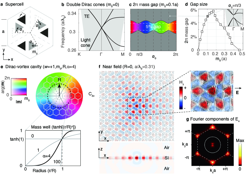
The starting point, in Fig. 1a, is a hexagon supercell consisting of three honeycomb primitive cells. This supercell folds the two Dirac points from Brillouin-zone boundary ( points below light cone) to the zone center ( point above light cone), forming a 4-by-4 double Dirac cone dispersion shown in Fig. 1b. The two honeycomb sub-lattices are colored in black and gray, both representing air-holes in the silicon membrane. The triangular shape of the air holes, compared to the circular shape, improves the frequency-isolation of the Dirac points Barik et al. (2016, 2018). We note that the previous waveguide design Wu and Hu (2015) between two deformed honeycomb lattices, by expanding and shrinking, actually corresponds to two discrete phase values of the Dirac mass (0 and 60∘).
We apply a generalized Kekulé modulation Hou et al. (2007) in the supercell to generate the 2 vortex mass (complex mass term with complete phase) to gap the double Dirac cones. Shown in Fig. 1a, the three gray sub-lattice (air holes) in the supercell are shifted from their original positions by the same amplitude of and correlated phase of . The key observation from the simulation result, shown in Fig. 1c, is the persistent gap opening for all 2 values of with non-zero . The gap closes at the vortex center where . Due to the symmetry of the supercell, the mass gap in Fig. 1c has an angular periodicity of and the minimal gap size occurs at . The gap size as a function of is plotted in Fig. 1d. The 2-mass-gap peaks at 6% and eventually closes for large because the band at point drops. Since the modulation vector has the same physical consequence as that of the complex Dirac mass in Eq. 1, we use the same symbol in this paper.
Now that we have a continuous library of supercells with a mass gap for an entire range of , the vortex cavity design is a matter of arranging these supercells angularly around a cavity center (), as illustrated in Fig. 1e. Since the original honeycomb lattice () have symmetry, the vortex cavity () can always remain symmetric if a -dependent symmetric vortex center () is chosen. A highly symmetric design reduces the computation domain and eases the analysis through group theory.
The topological mid-gap mode is plotted in Fig. 1f. The in-plane electric fields form spatial vortices, indicating the vector-beam far fields plotted in Fig. 2. The Fourier components of the mode clearly reveals its momentum distribution in relation to the light cone. Once the points move inside the light cone of the substrate, the Dirac vortex resonance is no longer well defined (see Sec. V).
III Cavity parameters
There is a large degree of freedom in designing the vortex mass . Without loss of generality, we choose the form of Eq. 2.
| (2) |
The mass-well function and , interpreting from the central zero mass to the boundary maximum mass . This Dirac-vortex cavity is determined by four parameters () as illustrated in Fig. 1e.
The first parameter is the winding number of the vortex. The magnitude determines the number (degeneracy) of mid-gap modes and the mode area generally increase with , similar to the topological fiber case Lu et al. (2018). The sign of is the mode chirality, determining the field distribution on the sub-lattices Jackiw and Rossi (1981). The topological mode populates only one of the honeycomb sub-lattice and populates the other sub-lattice when changes sign. This can be seen in Fig. 1f, where both the magnetic () and electric () fields peak only at the triangles pointing to the left.
The second parameter is the maximum Dirac mass, the depth of the mass well in Fig. 1e. is the maximum shift of the honeycomb sub-lattice in Fig. 1a, which should be greater than the size of fabrication disorder. is also the strength of radiative coupling that couples the two (originally guided) Dirac cones into the light cone (radiation continuum). Therefore the cavity increases as decreases.
The third parameter is the radius of the vortex, as illustrated in Fig. 1e. should not be mistaken as the size of the whole cavity, outside which the photonic-crystal pattern ends. We pad at least fifty extra periods outside the vortex radius to ensure sufficient mode confinement. We emphasize that can very different from the size of the confined optical mode. For example, in Fig. 1f, the mode size is non-zero while the vortex size is (). Also, the mode size also does not necessarily grow as fast as the vortex size; it depends on .
The fourth parameter is the shape factor — a positive exponent that controls the shape of the mass well, plotted in Fig. 1e. As a result, also controls the near field envelope and the radiation pattern of the cavity mode. We choose in experiments as a balance between radiative coupling and modal size scaling, as discussed in the next section.
IV Size scaling properties
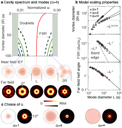
For high-power single-mode lasers, one prefers a cavity with broader modal area (or modal diameter ), larger free spectral range (FSR) and narrower beam divergence. These properties of the Dirac-vortex cavity are thus examined in Fig. 2 to see how they scale with the vortex size using effective 2D simulations. We find that the scaling properties are controlled by the shape factor .
We set for a single topological mode and choose a large mass gap () for large FSRs. A typical cavity spectrum is shown in Fig. 2a. For small cavities, the topological mode does not appear exactly at the gap center, due to the lack of chiral symmetry discussed in Sec. I. For large cavities, the topological mode always converges to the Dirac-point frequency, since the central area of the large cavity is approaching the unmodulated Dirac lattice with the original Dirac spectrum. As increases, the high-order non-topological cavity modes originate from the continuum of bulk modes above or below the bandgap. These high-order modes have both doublet and singlet states, due to the symmetry. The near fields and far fields of the singlet modes are plotted in Fig. 2a. The topological mode always has the largest and most uniform mode area, so that it will always experience the largest modal gain given a matching pumping area comparing to the non-topological modes in the cavity.
The modal diameter () increases with the vortex diameter (). For large , the scaling is shown in Fig. 2b. This is derived from the known result Jackiw and Rossi (1981) that the zero mode wavefunction is determined by the radial integration of the mass function: , according the mass definition in Eq. 2. The size of the topological mode grows sub-linearly with for finite . Although gives the ideal linear size scaling, the cavity is not emitting in the vortex area where (meaning zero radiative coupling). The radiation, when , only takes place at the step boundary, which is not ideal for the power input/output and the far field has multiple fringes as shown in Fig. 2c. Therefore, we choose the shape factor for its narrow far field and near linear scaling of .
Dirac-vortex cavity has a robustly large FSR that is essential for the single-mode operation. As denoted in Fig. 2a, the FSR of the Dirac-vortex cavity is the frequency separation between the mid-gap and the neighboring (doublet) modes. It has been pointed out Chua et al. (2014) that the FSR of a linear Dirac band edge () is much larger than the FSR of the usual quadratic band edge (), and can be arbitrarily larger in the large mode limit. However, the proposed accidental “Dirac point” at in Ref. Chua et al. (2014) is not robust to any system parameters, which means one can never, in reality, fabricate a device and operate at the exact accidental point consistently. In contrast, shown in Fig. 2b, our Dirac-vortex cavity has the same advantage for large FSR and this scaling is topologically robust against perturbations to any system parameters!
The far-fields of the singlet modes are vector-beams, as shown in Fig. 2a, obtained by integrating the near-fields using the Rayleigh-Sommerfeld diffraction theory. Since the polarization-degenerate free-space modes belong to the doublet representation of , the singlet cavity modes cannot couple out in the exact vertical direction due to the distinct representations. If the cavity symmetry is broken, one could convert the donut beam to a single-lobe beam Miyai et al. (2006). The beam angle is inversely proportional to the mode diameter in the large mode limit, as plotted in Fig. 2b. The far-field half angle is below 1∘ once the vortex diameter exceeds 200.
V Cavity on substrates
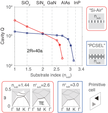
As a practical device, Dirac-vortex cavities can work on various substrates that dissipate heat, conduct current and provide mechanical support. In Fig. 3, we place the cavity on uniform substrates and compute the as a function of substrate refractive index () for two different core waveguide configurations: “Si-Air” and “PCSEL”. Both high-index () core waveguides are pattern with air. Both types of cavities have a limited vortex size of and are top-down symmetric to save computation resources. Note the cavity still increases for larger vortex sizes.
In the “Si-Air” configuration, we place the silicon-membrane studied in Fig. 1 on substrates. The cavity gradually decreases (in power law) with increasing until a critical index value where drops exponentially. This critical point is where the Dirac-point states, in the unperturbed primitive cell , are no longer guided in the core waveguide. This is shown in the band structures in Fig. 3, where the Dirac points almost merge into the light cones. This value already covers the common substrates such as silica, sapphire and gallium nitride.
In the “PCSEL” configuration, we aim to further increase and evaluate the technological potential of Dirac-vortex PCSELs. The data in Fig. 3 shows , which implies the compatibility with the current GaAs/AlGaAs material system used for PCSEL products HAM (2018). We note that GaAs actually has a higher index of 3.55 (than 3.4 used in our simulation) and our design is not optimized. Here, the “PCSEL” waveguide is twice as thick as the “Si-Air” waveguide with the air-hole pattern through half of its total thickness from top and bottom. (The asymmetric design of moving air holes to one side does not really change the results, but significantly increases the computation time.) This structure is very close to the epitaxy layers of the current PCSEL devices with air-hole maintained regrowth technique Hirose et al. (2014); Taylor et al. (2017).
It is worth pointing out that the topological resonance persists even when the Dirac point is not frequency isolated. Actually, when the mode area is large enough, the wavevectors of the mode are too localized (in momentum space) to couple to the other bulk states at the same frequency. We also note that high cavity () is undesirable for a high-power laser. Instead, a good laser cavity emits all its optical loss in the output direction. The Dirac vortex cavity has the suitable and emit only in the vertical direction. The bottom emission could be easily reflected using a metal coating or Bragg mirrors.
VI SOI experiments
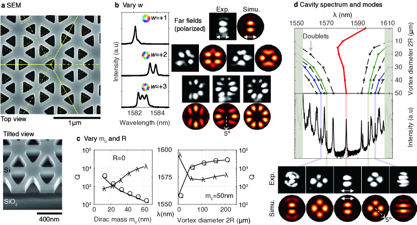
We perform the experiments on standard SOI Hafezi et al. (2013); Shalaev et al. (2018); He et al. (2019) at telecommunication wavelength to study the spectral and modal properties of the Dirac-vortex cavities with the shape factor . The scanning-electron-microscope (SEM) images of a typical device is shown in Fig. 4a. The photonic crystals were patterned in a 220 nm silicon layer by e-beam lithography and dry-etching. The underneath () cladding provides mechanical stability. The lattice constant () is 490 nm.
In Fig. 4b, cavities of different winding number are measured. Their spectra verify that the number of topological modes equals the winding number. The far fields of all topological modes compare favorably with our simulation results. These radiation patterns are captured after a horizontal polarizer in our cross-polarization setup. Consequently, the number of zero-intensity radial lines equals the topological charges (in magnitude) of these vector beams. We then focus on the single-mode case for the rest of the study.
In Fig. 4c, we plot the dependence of and wavelength () on the maximum Dirac mass () and the vortex diameter (). In both cases, increases with the increase of mode area. Because the mode area increases with the decrease of Dirac mass gap and the increase of vortex size.
Shown in Fig. 4d are the cavity spectra as a function of the vortex diameter. Consistent with the numerical results in Fig. 2a, the wavelength of topological mode converges to the Dirac wavelength when the vortex diameter increases to about 30m. We also track the high-order modes and a full spectrum is plotted for the cavity of . The polarized far fields of the singlet modes are imaged and are in agreement with the numerical results.
VII Discussion
With the advance of topological photonics Lu et al. (2014); Khanikaev and Shvets (2017); Ozawa et al. (2019), we are able to design a new on-chip optical microcavity Vahala (2003) with separate controls over mode number (), mode area (), radiation coupling () and far-field pattern (), which could outperform other cavities including the topological corner modes Noh et al. (2018); Ota et al. (2019); Mittal et al. (2019) for topological lasers Bahari et al. (2017); Harari et al. (2018); Bandres et al. (2018). For example, the corner or boundary modes are harder to scale uniformly in area, compared to the vortex cavity.
The Dirac-vortex cavity is the 2D upgrade of the 1D feedback structures in phase-shifted DFB and VCSEL, two widely used industrial semiconductor lasers. This topological cavity provides a single mid-gap mode with a large modal diameter continuously tunable from a couple of microns towards millimeter scale. In this work, we have studied the detailed optical properties of this passive cavity.
Next, by changing the lithography pattern, the Dirac-vortex PCSEL could be realized in the same III-V semiconductor platform as that of the current PCSELs Colombelli et al. (2003); HAM (2018); Matsubara et al. (2008); Hirose et al. (2014); Yoshida et al. (2019). The design advantages of a topological PCSEL could be as follows. i) It provides a unique single mid-gap mode for lasing. ii) It has a much larger FSR. Generally, FSR is much larger at the center of the linear Dirac spectrum, where the DOS vanishes, than that at the quadratic band edge where the DOS is a constant in 2D. iii) The hexagonal lattice generates more uniform in-plane feedback than that of the square lattice in current PCSEL devices. In fact, the square lattice was chosen over the hexagonal lattice only to reduce the number of high-Q band edge modes (2 instead of 4) and suppress multi-mode lasing, which is no longer an issue for the Dirac-vortex cavity. iv) The cavity design and the above benefits are topologically robust against fabrication errors. Finally, the employment of the Dirac-vortex cavity in PCSEL devices may lead to stabler operation or even brighter lasers.
Acknowledgements.
We thank Lin Gan and Yong Liang for helpful discussions. L.L. acknowledges his Ph.D advisor John D. O’Brien (1969-2017) for his teaching of photonic crystal lasers. L.L. was supported by the National key R&D Program of China under Grant No. 2017YFA0303800, 2016YFA0302400 and by NSFC under Project No. 11721404. Z.W. was supported by NSFC under Grant No. 11674189. F.B. was supported by NSFC under Grant No. 11734009 and 11674181.References
- Chuang (2009) Shun Lien Chuang, Physics of photonic devices (John Wiley & Sons, 2009) Chap. 11.
- Kogelnik and Shank (1971) H Kogelnik and CV Shank, “Stimulated emission in a periodic structure,” Applied Physics Letters 18, 152–154 (1971).
- Haus and Shank (1976) H Haus and C Shank, “Antisymmetric taper of distributed feedback lasers,” IEEE Journal of Quantum Electronics 12, 532–539 (1976).
- Sekartedjo et al. (1984) K Sekartedjo, N Eda, K Furuya, Y Suematsu, F Koyama, and T Tanbun-Ek, “1.5 m phase-shifted dfb lasers for single-mode operation,” Electronics Letters 20, 80–81 (1984).
- Wang and Sheem (1973) Shyh Wang and Sang Sheem, “Two-dimensional distributed-feedback lasers and their applications,” Applied Physics Letters 22, 460–462 (1973).
- Imada et al. (1999) Masahiro Imada, Susumu Noda, Alongkarn Chutinan, Takashi Tokuda, Michio Murata, and Goro Sasaki, “Coherent two-dimensional lasing action in surface-emitting laser with triangular-lattice photonic crystal structure,” Applied Physics Letters 75, 316–318 (1999).
- HAM (2018) Photonic Crystal Surface Emitting Laser Diode L13395-04, Tech. Rep. (HAMAMATSU PHOTONICS K.K., 2018).
- Matsubara et al. (2008) Hideki Matsubara, Susumu Yoshimoto, Hirohisa Saito, Yue Jianglin, Yoshinori Tanaka, and Susumu Noda, “Gan photonic-crystal surface-emitting laser at blue-violet wavelengths,” Science 319, 445–447 (2008).
- Hirose et al. (2014) Kazuyoshi Hirose, Yong Liang, Yoshitaka Kurosaka, Akiyoshi Watanabe, Takahiro Sugiyama, and Susumu Noda, “Watt-class high-power, high-beam-quality photonic-crystal lasers,” Nature Photonics 8, 406 (2014).
- Yoshida et al. (2019) Masahiro Yoshida, Menaka De Zoysa, Kenji Ishizaki, Yoshinori Tanaka, Masato Kawasaki, Ranko Hatsuda, Bongshik Song, John Gelleta, and Susumu Noda, “Double-lattice photonic-crystal resonators enabling high-brightness semiconductor lasers with symmetric narrow-divergence beams,” Nature Materials 18, 121 (2019).
- Jackiw and Rebbi (1976) R Jackiw and C Rebbi, “Solitons with fermion number 1/2,” Phys. Rev. D 13, 3398 (1976).
- Su et al. (1979) WP Su, JR Schrieffer, and Ao J Heeger, “Solitons in polyacetylene,” Physical Review Letters 42, 1698 (1979).
- Jackiw and Rossi (1981) R. Jackiw and P. Rossi, “Zero modes of the vortex-fermion system,” Nuclear Physics B 190, 681 – 691 (1981).
- Teo and Kane (2010) Jeffrey CY Teo and Charles L Kane, “Topological defects and gapless modes in insulators and superconductors,” Physical Review B 82, 115120 (2010).
- Hou et al. (2007) Chang-Yu Hou, Claudio Chamon, and Christopher Mudry, “Electron fractionalization in two-dimensional graphenelike structures,” Physical Review Letters 98, 186809 (2007).
- Iadecola et al. (2016) Thomas Iadecola, Thomas Schuster, and Claudio Chamon, “Non-abelian braiding of light,” Physical Review Letters 117, 073901 (2016).
- Menssen et al. (2019) Adrian J Menssen, Jun Guan, David Felce, Martin J Booth, and Ian A Walmsley, “A photonic majorana bound state,” arXiv preprint arXiv:1901.04439 (2019).
- Chen et al. (2019) Chun-Wei Chen, Natalia Lera, Rajesh Chaunsali, Daniel Torrent, Jose Vicente Alvarez, Jinkyu Yang, Pablo San-Jose, and Johan Christensen, “Mechanical analogue of a majorana bound state,” arXiv preprint arXiv:1905.03510 (2019).
- Noh et al. (2019) Jiho Noh, Thomas Schuster, Thomas Iadecola, Sheng Huang, Mohan Wang, Kevin P Chen, Claudio Chamon, and Mikael C Rechtsman, “Braiding photonic topological zero modes,” arXiv preprint arXiv:1907.03208 (2019).
- Barik et al. (2016) Sabyasachi Barik, Hirokazu Miyake, Wade DeGottardi, Edo Waks, and Mohammad Hafezi, “Two-dimensionally confined topological edge states in photonic crystals,” New Journal of Physics 18, 113013 (2016).
- Barik et al. (2018) Sabyasachi Barik, Aziz Karasahin, Christopher Flower, Tao Cai, Hirokazu Miyake, Wade DeGottardi, Mohammad Hafezi, and Edo Waks, “A topological quantum optics interface,” Science 359, 666–668 (2018).
- Wu and Hu (2015) Long-Hua Wu and Xiao Hu, “Scheme for achieving a topological photonic crystal by using dielectric material,” Physical Review Letters 114, 223901 (2015).
- Lu et al. (2018) Ling Lu, Haozhe Gao, and Zhong Wang, “Topological one-way fiber of second chern number,” Nature Communications 9, 5384 (2018).
- Chua et al. (2014) Song-Liang Chua, Ling Lu, Jorge Bravo-Abad, John D Joannopoulos, and Marin Soljačić, “Larger-area single-mode photonic crystal surface-emitting lasers enabled by an accidental dirac point,” Optics Letters 39, 2072–2075 (2014).
- Miyai et al. (2006) Eiji Miyai, Kyosuke Sakai, Takayuki Okano, Wataru Kunishi, Dai Ohnishi, and Susumu Noda, “Lasers producing tailored beams,” Nature 441, 946 (2006).
- Taylor et al. (2017) RJE Taylor, P Ivanov, G Li, DTD Childs, and RA Hogg, “Optimisation of photonic crystal coupling through waveguide design,” Optical and Quantum Electronics 49, 47 (2017).
- Hafezi et al. (2013) Mohammad Hafezi, S Mittal, J Fan, A Migdall, and JM Taylor, “Imaging topological edge states in silicon photonics,” Nature Photonics 7, 1001 (2013).
- Shalaev et al. (2018) Mikhail I Shalaev, Wiktor Walasik, Alexander Tsukernik, Yun Xu, and Natalia M Litchinitser, “Robust topologically protected transport in photonic crystals at telecommunication wavelengths,” Nature nanotechnology 14, 31 (2018).
- He et al. (2019) Xin-Tao He, En-Tao Liang, Jia-Jun Yuan, Hao-Yang Qiu, Xiao-Dong Chen, Fu-Li Zhao, and Jian-Wen Dong, “A silicon-on-insulator slab for topological valley transport,” Nature Communications 10, 872 (2019).
- Lu et al. (2014) Ling Lu, John D Joannopoulos, and Marin Soljačić, “Topological photonics,” Nature Photonics 8, 821–829 (2014).
- Khanikaev and Shvets (2017) Alexander B Khanikaev and Gennady Shvets, “Two-dimensional topological photonics,” Nature Photonics 11, 763 (2017).
- Ozawa et al. (2019) Tomoki Ozawa, Hannah M Price, Alberto Amo, Nathan Goldman, Mohammad Hafezi, Ling Lu, Mikael C Rechtsman, David Schuster, Jonathan Simon, Oded Zilberberg, et al., “Topological photonics,” Reviews of Modern Physics 91, 015006 (2019).
- Vahala (2003) Kerry J Vahala, “Optical microcavities,” Nature 424, 839 (2003).
- Noh et al. (2018) Jiho Noh, Wladimir A Benalcazar, Sheng Huang, Matthew J Collins, Kevin P Chen, Taylor L Hughes, and Mikael C Rechtsman, “Topological protection of photonic mid-gap defect modes,” Nature Photonics 12, 408 (2018).
- Ota et al. (2019) Yasutomo Ota, Feng Liu, Ryota Katsumi, Katsuyuki Watanabe, Katsunori Wakabayashi, Yasuhiko Arakawa, and Satoshi Iwamoto, “Photonic crystal nanocavity based on a topological corner state,” Optica 6, 786–789 (2019).
- Mittal et al. (2019) Sunil Mittal, Venkata Vikram Orre, Guanyu Zhu, Maxim A Gorlach, Alexander Poddubny, and Mohammad Hafezi, “Photonic quadrupole topological phases,” Nature Photonics 13, 692 (2019).
- Bahari et al. (2017) Babak Bahari, Abdoulaye Ndao, Felipe Vallini, Abdelkrim El Amili, Yeshaiahu Fainman, and Boubacar Kanté, “Nonreciprocal lasing in topological cavities of arbitrary geometries,” Science 358, 636–640 (2017).
- Harari et al. (2018) Gal Harari, Miguel A Bandres, Yaakov Lumer, Mikael C Rechtsman, Yi Dong Chong, Mercedeh Khajavikhan, Demetrios N Christodoulides, and Mordechai Segev, “Topological insulator laser: theory,” Science 359, eaar4003 (2018).
- Bandres et al. (2018) Miguel A Bandres, Steffen Wittek, Gal Harari, Midya Parto, Jinhan Ren, Mordechai Segev, Demetrios N Christodoulides, and Mercedeh Khajavikhan, “Topological insulator laser: Experiments,” Science 359, eaar4005 (2018).
- Colombelli et al. (2003) Raffaele Colombelli, Kartik Srinivasan, Mariano Troccoli, Oskar Painter, Claire F Gmachl, Donald M Tennant, A Michael Sergent, Deborah L Sivco, Alfred Y Cho, and Federico Capasso, “Quantum cascade surface-emitting photonic crystal laser,” Science 302, 1374–1377 (2003).