Layer Construction of Topological Crystalline Insulator LaSbTe
Abstract
Topological crystalline insulator (TCI) is one of the symmetry-protected topological states. Any TCI can be deformed into a simple product state of several decoupled two-dimensional (2D) topologically nontrivial layers in its lattice respecting its crystalline symmetries called the layer construction (LC) limit. In this work, based on first-principles calculations we have revealed that both tetragonal LaSbTe (t-LaSbTe) and orthorhombic LaSbTe (o-LaSbTe) can be interpreted as stacking of 2D topological insulators in each lattice space. The structural phase transition from t-LaSbTe to o-LaSbTe due to soft phonon modes demonstrates how the real space change can lead to the modification of topological states. Their symmetry-based indicators and topological invariants have been analyzed based on LC. We propose that LaSbTe is an ideal example demonstrating the LC paradigm, which bridges the crystal structures in real space to the band topology in momentum space.
I 1. Introduction
Topological crystalline insulators (TCIs) fu2011topological are topological states protected by crystalline symmetry as an extension of time-reversal (TR) symmetry protected topological insulators (TIs) hasan2010colloquium ; qi2011topological ; weng2015quantum . Three-dimensional (3D) weak TI protected by lattice translation can be obtained from stacking many copies of 2D TI in the third dimension. Heuristically, apart from translation, TCI protected by mirror symmetry has been found to be adiabatically connected to the limit of weakly coupled 2D topological states, and these 2D topological states can be TCIs characterized by mirror Chern number kim2015 or 2D Chern insulators Fulga2016 . These had inspired researchers to investigate TCIs based on such dimensional reduction argument, named as ”layer construction” (LC) scheme now. It has been demonstrated huang2017 ; hsong2017 ; Songzdarxiv1 ; Songzdarxiv2 that all crystalline point group symmetry-protected topological phases can be produced by stacking lower-dimensional blocks of topological states and the classification can be applied to both interacting bosons else2018 and free fermions prx_ashvin ; song2018quantitative . This approach provides a clear understanding of the physical nature of the crystalline symmetry-protected topological phase.
Song et al. song2018quantitative have exploited the LC scheme in very detail. They derived exhaustive mappings from symmetry data to topological invariants for arbitrary space groups in the presence of TR symmetry, providing an effective approach to define and search for new TCIs Zhang2018 ; Vergniory2019 ; wanxg2019 when combined with topological quantum chemistry (TQC) tqc2017 ; nc_ashvin ; Kruthoff2017 and symmetry-based indicators (SBI). LC decorates the lattice with 2D insulating layers with nontrivial number or mirror Chern number, while atomic insulators are constituted from proper atomic orbitals at Wyckoff positions. But the correspondence between an LC and the resulting TCI is not as intuitive as the atomic picture. Recently, A. Matsugatani et al. connected the high-order TIs (HOTIs) to lower-dimensional TIs using a tight-binding model to capture the essence of HOTIs haruki2018 . However, a realistic TCI material with layered crystal structure has yet to be demonstrated with exact one-to-one correspondence between the stacking of lower-dimensional topological phases in real space and the band topology.
In this paper, we introduce LaSbTe with two distinct crystal structures: tetragonal LaSbTe (t-LaSbTe) (a member of ( = Zr, Hf, or La, =Si, Ge, Sn, or Sb, and = O, S, Se, or Te) family xu2015two ) and orthorhombic LaSbTe (o-LaSbTe). When spin-orbit coupling (SOC) is taken into consideration, t-LaSbTe is a weak TI with one 2D TI in its unit cell, while o-LaSbTe is a TCI with two 2D TI layers per unit cell due to doubling of t-LaSbTe cell along the stacking direction during phase transition. Thus, o-LaSbTe can be viewed as an LC of two t-LaSbTe with proper lattice distortion, where each t-LaSbTe represents a layer of an elementary LC (eLC). To the best of our knowledge, this is the first demonstration of the LC scheme, in other words, mapping the crystal structures in real space to the band topology in momentum space and paves the way for understanding the physical essence of TCI.
II 2. Methodology
The Vienna ab initio simulation package (VASP) vasp with the projector augmented wave method paw1 ; paw2 based on density functional theory was employed for the first-principles calculations. The generalized gradient approximation (GGA) of Perdew-Burke-Ernzerhof type pbe was used for the exchange-correlation potential. The cut-off energy for plane wave expansion was set to 300 eV. The Brillouin zone (BZ) was sampled as grids of for t-LaSbTe and for o-LaSbTe in the self-consistent process, respectively. A width of 0.02 eV was adopted in the Gaussian smearing method for Fermi level determination. We employed the experimental lattice parameters charvillat1977cristallochimie ; dimasi1996stability and then fully relaxed the structure until the forces on all atoms were smaller than 0.01 eV/Å. The band structures were calculated with and without considering of SOC. Because of the weak coupling between quintuple layers (QLs), different forms of van der Waals (vdW) functional, including optPBE-vdW, optB88-vdW and optB86b-vdW were adopted to check the effect of vdW interactions on the topology Klime2010 ; Klime2011 ; vdw2007 . The WannierTools WU2017 was employed to compute the surface states based on the maximally localized Wannier function (MLWF) constructed by Wannier90 2012maximally . The phonon spectrum was computed by the Phonopy program based on the density functional perturbation theory (DFPT) togo2015first . The Wilson-loop technique was used to compute TR in a single-layer calculation.
III 3. Crystal structure
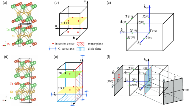
Two different crystal structures have been reported for LaSbTe. One is t-LaSbTe with tetragonal phase and space group (SG.) (No. 129). The relaxed lattice constants are Å and Å that are comparable with experimental values Å and Å. La and Te are at Wyckoff position with and , respectively. Sb is at . t-LaSbTe is one of the family materials, xu2015two which comprise stacked quintuple layers along the -axis, where QL is composed of five square nets in a sequence of [Te-La-Sb2-La-Te] wang1995main . QLs are bonded with each other along the -direction, as indicated by the dotted lines in Fig. 1 (a) and they are suggested to be weaker than the bonds among square nets in QL.
The other one is o-LaSbTe in orthorhombic phase with SG. (No. 62) with relaxed lattice constants Å, Å, and Å. The experimental lattice constants are Å, Å, and Å. La, Te and Sb are at Wyckoff position , , and , respectively. Compared with t-LaSbTe, two QLs take place in one unit cell of o-LaSbTe as the dimerization of QLs since the square-sheet layer of Sb in each QL is distorted, while Sb sheets in neighboring QLs distort in the opposite direction. o-LaSbTe has the inversion symmetry, a mirror plane (), two glide planes (, ) and three two-fold screw axes (, , ).
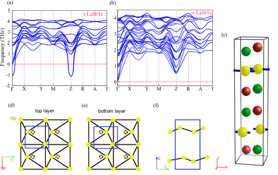
The structural difference in these two phases can be understood by studying their phonon spectra, which are calculated and shown in Fig. 2(a) and (b). The phonon spectrum of o-LaSbTe indicates it is the stable phase, while that of t-LaSbTe has soft modes with imaginary frequencies at and . The soft modes at (0, 0, 0.5) suggest that the doubling of the -axis would lead to a stable crystal structure. These soft modes mainly consist of Sb vibration modes as shown in Fig. 2(c), where Sb atoms in neighboring QLs shift in the opposite direction and lead to a rectangular in-plane lattice and a zigzag chain-like structure, as schematically depicted from both top and side views in Fig. 2(d-f). Such kind of lattice distortion corresponds to a structural transition from t-LaSbTe to o-LaSbTe. The soft modes at are from optical phonon branches, which would result in a phase transition to SG. 11. Nonetheless, the transition to o-LaSbTe with SG. 62 takes place, while the phase of SG. 11 has not been reported.
IV 4. Electronic band structures
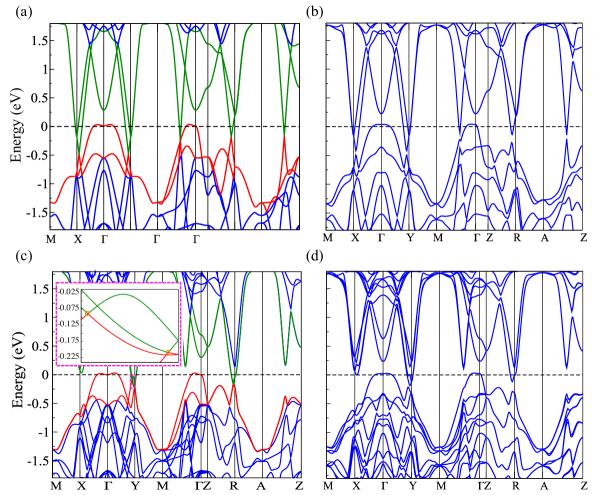
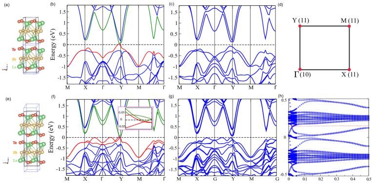
The band structures for t-LaSbTe and o-LaSbTe without and with SOC are shown in Fig. 3. As a family of compounds, t-LaSbTe has nodal lines when SOC is neglected xu2015two ; lou2016emergence since there are band crossings along , in plane and , in plane. All the nodal lines are gapped when SOC is further included and t-LaSbTe becomes a weak TI as a simple stacking of QLs (i.e., 2D TIs) xu2015two . There are also crossing points in the band structure of o-LaSbTe without SOC, which are parts of the nodal lines in the mirror plane as schematically shown in Fig. 1. Again, SOC opens the band gap along the nodal lines and o-LaSbTe becomes a TCI. Neither t-LaSbTe nor o-LaSbTe has a global band gap to be a real insulator; however, this might be improved by replacing the component atoms with heavier elements to enhance SOC splitting, or by proper lattice strain and pressure effect.
According to the theory of SBI nc_ashvin ; wanxg2019 , both t-LaSbTe and o-LaSbTe have inversion symmetry, and when SOC is considered, their symmetry indicators are , which can be easily calculated through Fu-Kane like formula song2018quantitative ; prx_ashvin . The three weak indices, denoted as , are obtained through
| (1) |
The indicator, denoted as is from:
| (2) |
where the () is the number of occupied Kramers pairs with parity at time-reversal invariant momentum (TRIM) . The number of occupied Kramers pairs with negative parity at eight TRIMs in the BZ has been marked in Fig. 1. Therefore, according to eq. 1 and eq. 2, we can get t-LaSbTe is a weak TI with being (0010) and o-LaSbTe is a TCI of (0002). Due to weak coupling between QLs, we adopt different vdW functionals to check the impact of vdW force on the topology PRB97 . After fully relaxed, we found optB86b-vdW functional gives a smaller lattice parameter than PBE functional, 9.58 Å for t-LaSbTe and 19.18 Å for o-LaSbTe, respectively. The topological properties are the same as our previous calculations. Therefore, we use the PBE functional for all subsequent calculations. It is known that each single layer (QL) of t-LaSbTe is a 2D TI xu2015two . After the phase transition, the distorted QL is still a 2D TI.[More details can be found in the Appendix A1.] The two QLs in one unit cell of o-LaSbTe are weakly coupled as a simple stacking. These differences, as well as their corresponding topological invariants and topological properties can be further understood through the LC scheme, which relates the real space crystal structure with the band topology in momentum space.
V 5. LC and Topological Invariants
Intuitively, t-LaSbTe can be looked as being constructed by putting a layer of 2D TI on the planes with Miller indices of (001; 1/2). Applying all the symmetrical operations of SG. 129 on this layer gives out the same Miller planes. Therefore, eLC of (001; 1/2) is shown in Fig. 1(b). It intersects -axis and -axis zero times and -axis once per unit cell, leading to the three weak topological invariants being 0, 0 and 1, respectively. The eLC of (001; 1/2) occupies only four inversion centers out of eight, which means the topological invariant protected by inversion symmetry for this eLC is convention-dependent and , . This eLC doesn’t occupy any rotation or screw axis, nor any mirror or glide plane. Further, it doesn’t lead to nonzero stacking invariant for any screw and glide symmetry. These mean the topological invariant due to rotation, screw, mirror or glide symmetries are all zero, and thus t-LaSbTe is a weak TI instead of TCI.
The structural phase transition from t-LaSbTe to o-LaSbTe has been revealed by the soft modes at of t-LaSbTe, leading to doubling of the unit cell along the -axis and shifts of atoms. Therefore, two 2D TIs decorating the lattice of o-LaSbTe in the Miller planes of (001; 1/4) and (001; 3/4) constitute the eLC of (001; 1/4) or (001;3/4) within the lattice of SG. 62. In the convention of choosing unit cell in this work, these two layers intersect all the three lattice vectors even times and . All the inversion centers, as marked in Fig. 1(e), are occupied by these two 2D TI layers; thus, and . Again, these two layers are not in any mirror or glide plane, nor do they pass through any rotation axis. However, they contribute nonzero glide-stacking-number for glide symmetry and nonzero screw-stacking-number for screw symmetries and . The corresponding topological hourglass invariant and screw invariant equal to one. By this approach, the topological state protected by TR and crystalline symmetries of o-LaSbTe has been fully determined. It is a TCI with symmetry indicators of and topological invariants of , and . More details about the LC of o-LaSbTe are provided in the Appendix A2.
VI 6. Topological Surface States from Topological Invariants
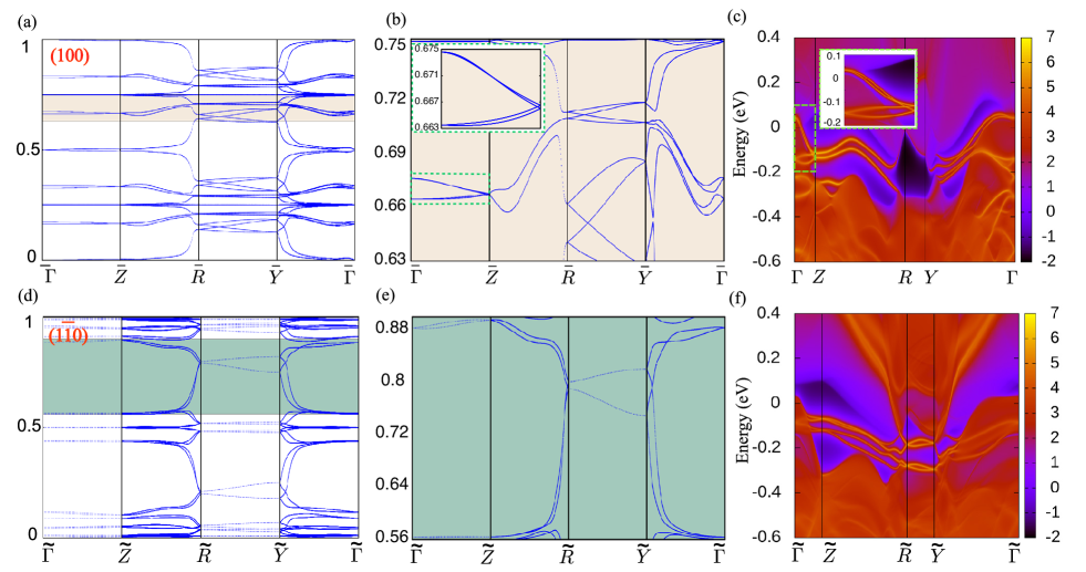
The nonzero hourglass invariant suggests that nontrivial hourglass surface state (SS) exists on the surface that preserves corresponding glide mirror symmetry wang2016hourglass ; bernevigprx . It is known that the Wilson-loop spectrum defining the bundle of occupied states over the BZ is isomorphic to the spectrum of SS fidkowski2011model . The hourglass invariant can be determined by calculating either the spectrum of Wilson loop based on bulk Hamiltonian, or the SS on the corresponding surface based on surface Green’s function method with truncated surface as the boundary condition WU2017 ; Sancho_1985 . For the hourglass invariant , it protects the nontrivial hourglass SS along the paths and on (100)-surface as shown in Fig. 1(f) since the glide plane is preserved and projected to them. The Wilson-loop spectra in Fig. 4 (a) and (b) clearly show that there are hourglass-like SSs along and . The connecting curves between these two hourglasses with a generalized zigzag pattern exhibit a spectral flow bernevigprx . In the SS calculation within Green’s function method, the hourglass-like SS along can be clearly reproduced in Fig. 4(c). However, the one along is hardly seen since it is mixed with the gapless bulk states. Similarly, is trivial and there should be no topological SS when projected along and on (10)-surface to maintain the glide symmetry . The hourglass-like spectra along and shown in Fig. 4(d) and (e) are trivial since the connection between them shows a spectrally isolated quadruplets with a full gap when viewed along in whole surface BZ and is consistent with the trivial topological SS band structure in Fig. 4(f).
The nontrivial screw invariant can lead to protected hinge states, which have been carefully discussed in several studies wang2016hourglass ; Fang2017 ; zhangt2019 and will not be presented here for simplicity.
VII 7. Conclusion
Based on the first-principles calculations, we conclude that a TCI phase o-LaSbTe with hourglass SS and hinge state can be viewed as stacking of two t-LaSbTe due to structural phase transition. This dimensional reduction method can effectively capture the physics of TCI. To the best of our knowledge, this is the first demonstration of a paradigm that visually maps the LC in real space to the band topology in momentum space for experimentally available material. For example, Ba3Cd2As4 zhangt2019 can also be considered as an LC: , but it cannot give an image that directly corresponds to the crystal structure in real space. Our paradigmatic demonstration offers an excellent platform to understand the underlying physics of TCIs and the relationship between TIs and TCIs.
Acknowledgments We acknowledge helpful discussions with Yi Jiang and Zhida Song. This work was supported by the National Natural Science Foundation of China under Grant Nos. 11504117, 11674369,11925408, 11921004 and 11974395. Zhiyun Tan acknowledges the Foundation of Guizhou Science and Technology Department under Grant No. QKH-LHZ[2017]7091. Zhijun Wang acknowledges support from the National Thousand-Young-Talents Program, the CAS Pioneer Hundred Talents Program, and the National Natural Science Foundation of China. Hongming Weng acknowledges support from the National Key Research and Development Program of China (Grant Nos. 2016YFA0300600, 2016YFA0302400, and 2018YFA0305700), the K. C. Wong Education Foundation (GJTD-2018-01).
References
- (1) Liang Fu. Physical Review Letters, 106(10):106802, 2011. arXiv: 1010.1802
- (2) M Zahid Hasan and Charles L Kane. Reviews of modern physics, 82(4):3045, 2010. arXiv:1002.3895
- (3) Xiao-Liang Qi and Shou-Cheng Zhang. Reviews of Modern Physics, 83(4):1057, 2011. arXiv:1008.2026
- (4) Hongming Weng, Rui Yu, Xiao Hu, Xi Dai, and Zhong Fang. Advances in Physics, 64(3):227–282, 2015. arXiv: 1508.02967
- (5) Youngkuk Kim, C. L. Kane, E. J. Mele, and Andrew M. Rappe. Phys. Rev. Lett., 115:086802, Aug 2015. arXiv: 1503.05966
- (6) I. C. Fulga, N. Avraham, H. Beidenkopf, and A. Stern. Phys. Rev. B, 94:125405, Sep 2016. arXiv: 1605.00652
- (7) Sheng-Jie Huang, Hao Song, Yi-Ping Huang, and Michael Hermele. Phys. Rev. B, 96:205106, Nov 2017. arXiv: 1705.09243
- (8) Hao Song, Sheng-Jie Huang, Liang Fu, and Michael Hermele. Phys. Rev. X, 7:011020, Feb 2017. arXiv: 1604.08151
- (9) Zhida Song, Chen Fang, and Yang Qi. arXiv:1810.11013.
- (10) Zhida Song, Sheng-Jie Huang, Yang Qi, Chen Fang, and Michael Hermele. arXiv:1810.02330.
- (11) Ryan Thorngren and Dominic V. Else. Phys. Rev. X, 8:011040, Mar 2018.
- (12) Eslam Khalaf, Hoi Chun Po, Ashvin Vishwanath, and Haruki Watanabe. Physical Review X, 8(3):31070, 2018. arXiv: 1711.11589
- (13) Zhida Song, Tiantian Zhang, Zhong Fang, and Chen Fang. Nature communications, 9(1):3530, 2018. arXiv: 1711.11049
- (14) Tiantian Zhang, Yi Jiang, Zhida Song, He Huang, Yuqing He, Zhong Fang, Hongming Weng, and Chen Fang. Nature, 566:475–479,2019. arXiv: 1807.08756
- (15) M. G. Vergniory, L. Elcoro, Claudia Felser, Nicolas Regnault, B. Andrei Bernevig, and Zhijun Wang. Nature, 566(7745):480–485, 2019. arXiv: 1807.10271
- (16) Feng Tang, Hoi Chun Po, Ashvin Vishwanath, and Xiangang Wan. Nature, 566(7745):486–489, 2019.
- (17) Barry Bradlyn, L. Elcoro, Jennifer Cano, M.G. Vergniory, Zhijun Wang, C. Felser, M. I. Aroyo, and B. Andrei Bernevig. Nature, 547:298–305, 2017. arXiv:1703.02050
- (18) Hoi Chun Po, Ashvin Vishwanath, and Haruki Watanabe. Nature Communications, 8(1):241–250, 2017. arXiv: 1703.00911
- (19) Jorrit Kruthoff, Jan De Boer, Jasper Van Wezel, Charles L. Kane, and Robert Jan Slager. Physical Review X, 7(4):1–23, 2017. arXiv: 1612.02007
- (20) Akishi Matsugatani and Haruki Watanabe. Phys. Rev. B, 98:205129, Nov 2018. arXiv: 1804.02794
- (21) Qiunan Xu, Zhida Song, Simin Nie, Hongming Weng, Zhong Fang, and Xi Dai. Physical Review B, 92(20):205310, 2015. arXiv: 1509.01686
- (22) G. Kresse and J. Furthmüller. Phys. Rev. B, 54:11169–11186, Oct 1996.
- (23) Peter E Blöchl. Physical review B, 50(24):17953, 1994.
- (24) Georg Kresse and D Joubert. Physical Review B, 59(3):1758, 1999.
- (25) John P. Perdew, Kieron Burke, and Matthias Ernzerhof. Phys. Rev. Lett., 77:3865–3868, Oct 1996.
- (26) J Charvillat, D Damien, and A Wojakowski. Rev. Chim. Miner, 14(14):178–188, 1977.
- (27) E DiMasi, B Foran, MC Aronson, and S Lee. Physical Review B, 54(19):13587, 1996.
- (28) Klimeš, Jiří and Bowler, David R and Michaelides, Angelos. Journal of Physics Condensed Matter, 22:022201, Jan 2010.
- (29) Klimeš, Jiří and Bowler, David R and Michaelides, Angelos. Phys. Rev. B, 83:195131, May 2011. arXiv: 1102.1358
- (30) Thonhauser, T. and Cooper, Valentino R. and Li, Shen and Puzder, Aaron and Hyldgaard, Per and Langreth, David C. Phys. Rev. B, 76:125112, Sep 2007. arXiv: cond-mat/0703442
- (31) QuanSheng Wu, ShengNan Zhang, Hai-Feng Song, Matthias Troyer, and Alexey A Soluyanov. Computer Physics Communications, 224:405–416, 2018. arXiv: 1703.07789
- (32) Nicola Marzari, Arash A Mostofi, Jonathan R Yates, Ivo Souza, and David Vanderbilt. Reviews of Modern Physics, 84(4):1419, 2012. arXiv: 1112.5411
- (33) Atsushi Togo and Isao Tanaka. Scripta Materialia, 108:1–5, 2015.
- (34) Chwanchin Wang and Timothy Hughbanks. Inorganic Chemistry, 34(22):5524–5529, 1995.
- (35) R Lou, J-Z Ma, Q-N Xu, B-B Fu, L-Y Kong, Y-G Shi, P Richard, H-M Weng, Z Fang, S-S Sun, et al. Physical Review B, 93(24):241104, 2016. arXiv: 1601.07294
- (36) Guohua Gao, Huijun Liu, Jinghua Liang, Long Cheng, Dengdong Fan, Zhenyu Zhang. Phys. Rev. B, 97:075147, Feb 2018.
- (37) Zhijun Wang, Aris Alexandradinata, Robert J Cava, and B Andrei Bernevig. Nature, 532(7598):189, 2016. arXiv: 1602.05585
- (38) A. Alexandradinata, Zhijun Wang, and B. Andrei Bernevig. Physical Review X, 6(2):021008, apr 2016. arXiv: 1604.03952
- (39) Lukasz Fidkowski, TS Jackson, and Israel Klich. Physical review letters, 107(3):036601, 2011. arXiv: 1101.0320
- (40) M P Lopez Sancho, J M Lopez Sancho, J M L Sancho, and J Rubio. Journal of Physics F: Metal Physics, 15(4):851–858, apr 1985.
- (41) Chen Fang and Liang Fu. arXiv:1905.07253.
- (42) Tan Zhang, Changming Yue, Tiantian Zhang, Simin Nie, Zhijun Wang, Chen Fang, Hongming Weng, and Zhong Fang. Phys. Rev. Research, 1:012001, Aug 2019. arXiv: 1905.07253
Appendix A APPENDIX
A1. Single-layer calculations of o-LaSbTe
In this section, we determine whether one QL of o-LaSbTe is a 2D TI and two QLs of o-LaSbTe is a trivial insulator. First, we construct a corresponding single-layer structure for these two cases, as shown in Fig. 5(a) and (e). Then, we compute the band structures without and with considering SOC. Without SOC, there are one band inversion and double band inversions along for one QL and two QLs, respectively. When SOC is considered, these two cases are fully gapped so that the TR can be well defined. Since one QL keeps inversion symmetry, can be simply derived by Fu-Kane formula. According to eq.1, we obtain for one QL. However, for two QLs, inversion symmetry is broken. Therefore, the Wilson-loop method is employed to calculate the Wannier-center flow. equals zero because the number of crossings between the Wilson-loop bands and reference line is even. By calculating index, we confirm each QL of o-LaSbTe is a well-defined 2D TI and stacking two weakly coupled 2D TIs can generate a normal insulator with trivial index.
A.1 A2. LC of o-LaSbTe
The LC method has been introduced to map the symmetry-based indicator and topological invariants song2018quantitative . For t-LaSbTe with SG., our convention is the same as in Ref song2018quantitative , so we can directly use the eLC of SG.129 as provided in Supplementary Table 5 of Ref song2018quantitative . However, for o-LaSbTe with SG. in this work, the convention is different from that in Ref song2018quantitative . Then, we derive the eLC of SG. and tabulate it in Table 1. The second eLC (001;1/4) in Table 1 represents the eLC of o-LaSbTe.
| weak | |||||||||
| 001;0 | 0000 | 000 | 00 | 1 | 1 | 0 | 0 | 1 | 1 |
| 001; | 0002 | 000 | 00 | 1 | 0 | 1 | 1 | 0 | 1 |
| 100; | 0000 | 000 | 20 | 0 | 1 | 0 | 1 | 0 | 1 |