Three-dimensional entanglement on a silicon chip
Abstract
Entanglement is a counterintuitive feature of quantum physics that is at the heart of quantum technology. High-dimensional quantum states offer unique advantages in various quantum information tasks. Integrated photonic chips have recently emerged as a leading platform for the generation, manipulation and detection of entangled photons. Here, we report a silicon photonic chip that uses interferometric resonance-enhanced photon-pair sources, spectral demultiplexers and high-dimensional reconfigurable circuitries to generate, manipulate and analyse path-entangled three-dimensional qutrit states. By minimizing on-chip electrical and thermal cross-talk, we obtain high-quality quantum interference with visibilities above 96.5% and a maximally entangled qutrit state with a fidelity of 95.5%. We further explore the fundamental properties of entangled qutrits to test quantum nonlocality and contextuality, and to implement quantum simulations of graphs and high-precision optical phase measurements. Our work paves the path for the development of multiphoton high-dimensional quantum technologies.
Introduction
Entanglement is a central resource for quantum-enhanced technology, including quantum computation ladd2010 , communication gisin2002 and metrology giovannetti2011 . To demonstrate the advantage of quantum systems, it is necessary to generate, manipulate and detect entangled states. Quantum states span the Hilbert space with a dimensionality of dn, where is the dimensionality of a single particle and n is the number of particles in the entangled states. Most of the widely-used quantum information processing protocols are based on qubits, a quantum system with d=2. Recently, higher-dimensional entangled states (qudits, d2) have gained substantial interest, owing to their distinguishing properties. For example, qudits provide larger channel capacity and better noise tolerance in quantum communication dambrosio2012 ; graham2015 ; luo2019 ; hu2019experimental , as well as higher efficiency and flexibility in quantum computing lanyon2009 ; Qiang et al. (2018) and simulations neeley2009 . From the fundamental point of view, qudits also provide stronger violations of Bell inequalities dada2011 , lower bounds for closing the fair-sampling loopholes in Bell tests vertesi2010 and possibilities to test contextuality lapkiewicz2011 . Recent reviews on the high-dimensional entanglement can be found in refs. erhard2019 ; wang2019integrated .
High-dimensional entangled photons have been realized in various degrees of freedom (DOFs), including orbital angular momentum (OAM) dada2011 ; wang2015 , frequency kues2017 ; imany2018 , path schaeff2015 ; wang2018 , temporal Thew:2004:ERE:2011577.2011578 ; Richart:2012hk and hybrid time-frequency modes reimer2019 . In particular, path-entangled photon pairs have been studied with a view to quantum information processing, where they are particularly attractive due to their conceptual simplicity Reck:1994wd . However, the generation of high-dimensional path-entangled photon pairs typically requires the simultaneous operation of several coherently pumped indistinguishable photon-pair sources and several multi-path interferometers with high phase stability schaeff2012 . As the dimensionality increases, the phase stabilization quickly becomes a daunting task in experiments based on bulk and fibre optical elements.
Integrated photonic circuits based on silicon offer dense component integration, high optical non-linearity and good phase stability, which are highly desirable properties for photonic quantum technology mower2011 ; collins2013 ; Silverstone:2014fu ; Harris:2014wa ; Silverstone:2015cl ; feng2016 . Moreover, silicon photonic devices are routinely fabricated in complementary metal oxide semiconductor (CMOS) processes. Therefore, a new field called silicon quantum photonics has recently been developed and has emerged as a promising platform for large-scale quantum information processing silverstone2016 . Recent advances of on-chip high-dimensional entanglement have employed frequency-encoding generated from a micro-resonator photon-pair source kues2017 and path-encoding generated from meander waveguides photon-pair source wang2018 . Specifically, silicon waveguides with cm-length are often employed as sources to create photon-pairs Qiang et al. (2018); wang2018 ; Silverstone:2014fu . However, the natural bandwidth of the photons generated from meander waveguides is about 30 nm wang2018 . In order to obtain high-quality photons, it is necessary to employ band-pass filters (1nm bandwidth in ref. wang2018 ), which unavoidably reduces the photon count rate drastically.
In this work, we employ a silicon photonic chip using an advanced resonator source embedded in Mach-Zehnder interferometers (MZIs) to generate, manipulate and characterize path-entangled qutrits (d=3). Cavity-enhanced processes and independent tuning capabilities of the coupling coefficients of pump, signal and idler photons allow us to generate high-indistinguishable and high-brightness photons without using passive filtering. The bandwidth of the photon generated from our source is about 50 pm, about a factor of 600 narrower to that of ref. wang2018 . This narrow-band feature not only provides high-quality single photons, but also holds the promise for direct coupling with telecom quantum memory saglamyurek2015 , which is not possible for the nanowire source due to the prohibitive low count rate after GHz bandwidth filtering. In particular, we perform on-chip test of quantum contextuality with closed compatible loophole. Furthermore, using the entangled qutrit state, we simulate a two-vertex and three-edge graph and obtain the number of the perfect matchings of this graph, which is in the P-complete complexity class valiant1979 . Although the structure of the graph of our demonstration is simple, it can be viewed as the first step towards achieving the ambitious goal of solving P hard problem with quantum photonic devices. We also employ our device to demonstrate the excellent phase sensitivity, exceeding both classical three-path linear interferometer and quantum second-order nonlinear interferometer limits. To be best of our knowledge, none of these three experiments have ever been realized with an integrated chip.
Results
Silicon quantum photonic chip and experimental setup
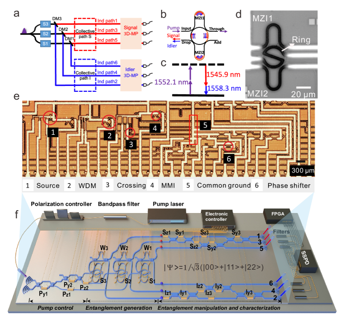
We have employed a scalable scheme for generating high-dimensional entangled states schaeff2012 . As shown in the conceptual scheme (Fig.1 a), entangled qutrits are generated by three coherently pumped non-degenerate spontaneous four wave mixing (SFWM) photon-pair sources, in which two pump photons generate one signal photon and one idler photon with different wavelengths (Fig.1 b and c). The signal and idler photons are separated by dichroic mirrors (DMs) and then sent through reconfigurable linear optical circuits for implementing arbitrary 3-D unitary operations via three-dimensional multiports (3D-MPs). Finally, we verify and harness the qutrit entanglement by detecting single photons at the outputs.
To obtain an efficient photon-pair source, we use a dual Mach-Zehnder interferometer micro-ring (DMZI-R) photon-pair source Tison et al. (2017); vernon2017 . Such a DMZI-R photon-pair source is inspired by the design of a wavelength division multiplexer (WDM) in classical optical communication Barbarossa et al. (1995) and could circumvent the trade-off between the utilization efficiency of the pump photon and the extraction efficiency of the signal and idler photon pairs from a ring resonator vernon2016 . The DMZI-R photon pair source was first demonstrated in ref. Tison et al. (2017), where enhanced coincidence efficiency of a single source was shown. The working principle of the DMZI-R photon source is as follows: by wrapping two pulley waveguides around a ring resonator, one can construct a four-port device, as shown in Fig. 1b. We couple each waveguide at two points to the resonator, using four directional couplers. By adjusting the relative phases of two waveguides to the resonator, we can tune the coupling between waveguides to the resonator at the pump, signal and idler wavelengths independently. In the ideal case, we would like to have the pump circulate in the ring resonator to generate photon pairs, and therefore, the critical coupling condition for the pump is preferred. On the other hand, we want to extract the signal and idler photons from the resonator as soon as they are generated to minimize the propagation loss of photon pairs in the resonator. As a consequence, it is desirable to over-couple the waveguide to the resonator at the wavelengths of signal and idler photons. These two requirements can be fulfilled simultaneously by setting the free spectral range (FSR) of the MZIs to be twice that of the ring, such that every second resonance of the ring is effectively suppressed. By doing so, we can achieve the desired distinct coupling conditions for the pump, signal and idler photons and maximally utilize the pump to efficiently extract photon pairs. The ring has a radius of 15 m and a coupling gap of 250 m (200 m) at the input (output) side. The length difference of the unbalanced MZI1 (MZI2) is 47.8 m (48 m). Optical microscopy images of the DMZI-R photon-pair source and the whole entangled qutrit chip are shown in Fig. 1d and e, respectively. Note that the sizes of the gaps of critical and over-critical couplings depend on the propagating loss of the photons in the ring. One should be able to obtain a higher count rate by optimizing the gap size Tison et al. (2017) (see Supplementary Information for a theoretical analysis and a detailed characterization of the DMZI-R photon source).
Following the DMZI-R photon pair source, we use an asymmetric MZI (AMZI) as an on-chip WDM to separate the non-degenerate signal and idler photons. As shown in Fig. 1f, we repeat this combination of DMZI-R source and WDM three times, and excite these sources coherently. When the generation rate is the same for all three sources and the relative phases of the pump are all zero, we generate a maximally entangled state of two qutrits: . Note that , and are the individual path states of single photons.
Each qutrit can be locally manipulated by a 3D-MP Reck:1994wd , which is composed of thermo-optic phase shifters (PSs) and multi-mode interferometers (MMIs). In particular, one of the essential components, formed by a single PS and a tunable beam splitter, is realized with an MZI, consisting of two balanced MMIs and a PS.These components are used to realize R and R rotations, and thus to obtain an arbitrary SU(2) operation in the two-dimensional subspace. Note that our experimental configuration is also closely related to a recent proposal on generating OAM entanglement by path identity krenn2017entanglement . The collective paths and individual paths in our work correspond to the path and OAM in ref. kysela2019 . After manipulating and characterizing the entangled qutrits with two 3D-MPs, both the signal and idler photons are coupled out from the chip, filtered to suppress residual pumping with off-chip filters, and detected with superconducting nanowire single-photon detectors (SSPDs). The single-photon detection events are recorded by a field-programmable gate array (FPGA)-based time-tag unit. Then both single counts and coincidence counts CCij between path i (i=1,3,5) and path j (j=2,4,6) are extracted from these timetag records (see Supplementary Information for further experimental details).
From qubit entanglement to qutrit entanglement
To generate three-dimensional (3D) path-entangled photons, it is necessary to ensure that all three coherently pumped photon-pair sources are identical. This means that the emitted photon pairs from different sources should be the same in all DOFs, including polarization, spatial mode, count rate and frequency. For our chip-based system, we use single-mode waveguides, which automatically give us the same polarization states and spatial modes of photons from different sources. However, the count rate and frequency of the photons are not necessarily identical for different sources. To eliminate the count rate distinguishability, we can tune the pump power of the individual source. The last DOF is the frequency. In non-resonant broad band (nm to tens of nm) photon-pair sources, such as silicon nanowires, one can use off-chip narrow-band filtering to post-select identical spectra of different photons Qiang et al. (2018); wang2018 , which unavoidably reduces the count rate. In the resonant sources, such as our DMZI-R source, we can actively tune the resonance wavelengths of each individual source with PSs. In doing so, we obtain identical photons without sacrificing the photon count rate, which is particularly important for multi-photon high-dimensional experiments. However, aligning the frequency of the narrow-band photons generated from resonance-enhanced sources is challenging within the sub-mm foot-print of our chip. The reasons are follows: silicon has a relatively high thermo-optic coefficient. On the one hand, this feature of silicon is desirable for realizing reconfigurable photonic circuits by using thermo-optic PSs with low power consumption. On the other hand, it presents an experimental challenge to stabilize the frequency of the single photons generated from resonance-enhanced photon-pair sources under several distinct configurations of thermal PSs, due to thermal cross-talk carolan2019 .
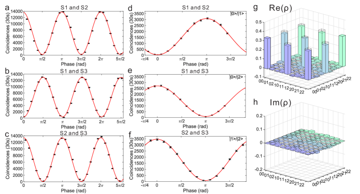
As the first step to generate 3D entanglement, we verify the identicality of two sources with time-reversed Hong-Ou-Mandel (RHOM) interference chen2007 . Highly indistinguishable photons produce the high visibility of RHOM interference. We investigate the indistinguishability between all pairs of the three sources by interfering signal-idler photon pairs generated from S1, S2 and S3 on the top 3D-MP. For instance, we set the phases Sy1 and Sy2 to be and Sy3 to be and scan the phase of Sz3 to obtain the RHOM interference fringe between S2 and S3. The RHOM interference fringes between S1 and S2, S1 and S3, and S2 and S3 are shown in Fig.2a, b and c, respectively. The visibility of the fringe is defined as V=(CCmax-CCmin)/(CCmax+CCmin), where CCmax and CCmin are the maximum and minimum of the coincidence counts. The measured visibilities are greater than 96.49% in all cases, indicating high-quality spectral overlaps. All of our data are raw, and no background counts are subtracted. To obtain high interference visibilities, we have spent significant amount of efforts to eliminate thermal noise (see Supplementary Information for further experimental details). We believe that by using better designs of the thermal PSs such as reported in ref. Harris et al. (2014); gao2019 , the noise can be greatly mitigated. In additional to reduce cross-talks, for reaching a visibility required for the practical applications, high-fidelity quantum control is a necessity. Remarkably, previous work has shown one can achieve excellent on/off ratio (60.5 dB), equivalent to having a Pauli-Z error rate of wilkes2016 by using cascaded MZIs. Over 100 dB pass-band to stop-band contrast filters have also been realized by cascaded microrings ong2013 and AMZIs piekarek2017 , respectively. By combining these high-performance devices, we believe integrated quantum photonics is a promising route in the development of future quantum technologies and applications rudolph2017 .
The next step is to verify the qubit entanglement of path states between three different pairs of sources. We measure the correlation of path entangled states in mutually unbiased bases (MUBs). We set the measurement base of the signal photon to be the coherent superpositions of the computational base, , where (j,k)= (0,1),(0,2),(1,2). Then, we scan the phase in the quantum state of the idler photon, and measure the coincidence counts between the signal and idler photons. The coincidence fringes are shown in Fig. 2d, e and f for S1 and S2, S1 and S3, and S2 and S3, respectively. The values of various visibilities range from 94.72%0.50% to 97.50%0.38%, indicating high-quality qubit entanglement. The phase doubling signature of RHOM fringes compared to the correlation counterparts can be seen by comparing Fig. 2a b and c, and Fig. 2d, e and f. In the RHOM experiment, both signal and idler photons create a coherent superposition of two photons in two paths, the state that evolves under a phase shift in one of the modes then displays phase doubling chen2007 . Note that the count rate of the path-correlation measurement is lower than that of the RHOM measurement, mainly because the design of the on-chip WDM is not optimal. Higher count rates of the correlation measurement can be achieved by optimizing the length difference between the two arms of the WDM.
Having established high-quality qubit entanglement, we proceed to characterize the qutrit entangled state with complete high-dimensional quantum-state tomography (QST). We use a set of all possible combinations of Gell-Mann matrices and apply the corresponding settings to both 3D-MPs thew2002 . The QST method takes approximately 33 mins with a typical count rate 100Hz per setting. Figure 2g and h display the real and imaginary parts of the reconstructed density matrix of the state, respectively, showing good agreement between the maximally entangled and measured quantum states with a fidelity of 95.50%0.17%. The maximum matrix element of the imaginary part is smaller than 0.015. From the reconstructed density matrix, we obtain an I-concurrence of 1.1490.002 fedorov2011 . The uncertainties in state fidelity extracted from these density matrices are calculated using a Monte Carlo routine assuming Poissonian statistics. In the context of quantum communication, a multi-dimension entanglement-based Ekert91 QKD protocol ekert1991 was initially proposed and analyzed in refs. cerf2002 ; bruss2002 , where high-dimension mutually unbiased bases correlations between two Alice and Bob can be used to generate keys. The upper bound error rate (ER) that guarantees security against coherent attacks for device-dependent QKD in three dimensions is 15.95%. For a maximally qutrit entangled state, the fidelity (F) of the state can be used to infer the ER if Alice and Bob use the same MUB zhu2019 ; that is F=(3-4ER)/3. From the fidelity we obtain, the ER is only 3.375%, which is considerably below the required bound, indicating the high quality of our qutrit state.
Tests of quantum nonlocality and contextuality with entangled qutrits
To benchmark the high-quality qutrit entanglement and high-precision quantum control, we demonstrate experimental tests of quantum nonlocality and quantum contextuality. Violations of Bell inequalities based on local realistic theories provide evidence of quantum nonlocality. It has been demonstrated that, high-dimensional correlations compatible with local realism satisfy a generalized Bell-type inequality, the Collins-Gisin-Linden-Massar-Popescu (CGLMP) inequality, with Ifor all d collins2002 . Expression I3 is given by joint probabilities as
| (1) |
where P with (a,b=1,2) and (k=0,1) represent the joint probabilities for the outcomes of that differ from by k. The measurement bases used to maximise the violation of Eq. for the maximally entangled state are defined as
| (2) |
| (3) |
where i=, , , and , and {0, 1, 2} denote Alice’s and Bob’s measurement outcomes respectively, and denotes the computational basis. These measurement bases can be implemented by configuring PSs in the 3D-MPs. For instance, we set Sz1 =, Sy1 = , Sz2 =, Sy2 = ,Sz3 = and Sy3 = to realize setting A1. In the context of quantum computation, entanglement is the essential resource. For one-way quantum computation, ref.reimer2019 reported the noise sensitivity of a two-photon, three-level and four-partite (two DOFs) cluster state with entanglement witness. CGLMP inequality is an entanglement criterion with higher correlation requirements comparing to entanglement witness. We witness the existence of entanglement between two qutrits in our experiment by using CGLMP inequality. The classical bound is violated by 51.46 (), benchmarking the resilience to errors. The experimental results for the four base settings are shown in Table 1.
| Probability | Result | Expected value |
|---|---|---|
| P(=) | 0.76640.0059 | 0.8293 |
| P(=-1) | 0.14800.0050 | 0.1111 |
| P(=) | 0.80980.0054 | 0.8293 |
| P(=+1) | 0.10300.0042 | 0.1111 |
| P(=-1) | 0.82920.0052 | 0.8293 |
| P(=) | 0.10140.0041 | 0.1111 |
| P(=) | 0.80110.0055 | 0.8293 |
| P(=-1) | 0.12330.0045 | 0.1111 |
Contextuality is a fundamental concept in quantum mechanics kochen1967 ; klyachko2008 ; kirchmair2009 ; lapkiewicz2011 and an important resource for fault-tolerant universal quantum computation howard2014 . A single qutrit is the simplest quantum system showing the contradiction between non-contextual hidden-variable models and quantum mechanics lapkiewicz2011 . However, the testability of the Kochen-Specker (KS) theorem is debated due to the finite precision in a single qutrit in practical experiments meyer1999 ; kent1999 . An approach based on maximally entangled qutrit pair has been proposed cabello2011 , which was recently realized with bulk optics hu2016 .
The experimental setting is as follows. A pair of maximally entangled qutrits is sent to two parties, Alice (A) and Bob (B). Alice performs projective measurements, either or , , and Bob simultaneously performs measurement , where and are dichotomic projectors with two possible outcomes, 0 or 1, and and are trichotomic projectors with three possible outcomes, , or . These four projectors are defined as and , where , , and . The non-compatibility loophole contextuality inequality can be expressed as cabello2011 :
| (4) |
where stands for the conditional probability of Alice obtaining result for when Bob also obtains result with . and are defined analogously. For our experiment, we need to reconfigure two 3D-MPs according to these projectors and measure the coincidence counts to reconstruct the conditional probabilities in Eq. . For example, can be projected to port 3 by setting Sz1 =, Sy1 = , Sz2 =, Sy2 =, Sz3 = and Sy3 =. We experimentally violate the non-contextuality inequality by 9.5 standard deviations (). The detailed experimental results are listed in Table 2. The no-signalling conditions, confirming the compatibility assumption between the measurements of Alice and Bob, are checked, as shown in Table 3. The results deviate slightly from 0 because of experimental imperfections.
| Conditional probability | Result | Expected value |
|---|---|---|
| 0.12450.0080 | 0.111 | |
| 0.02530.0035 | 0 | |
| 0.01360.0027 | 0 |
| Probability | Result |
|---|---|
| 0.0236 0.0089 | |
| 0.0094 0.0088 | |
| 0.0330 0.0087 |
Harnessing two-qutrit quantum correlations: quantum simulation of graphs and quantum metrology
High-order quantum correlations are unique properties of high-dimensional entangled quantum systems and are a central resource for quantum information processing. To probe the quantum correlations in the entangled qutrit system, we measure the coincidence counts between signal and idler photons under different MUBs by tuning both the phases of signal/idler and pump photons. Here we use the quantum correlation between two entangled qutrits to demonstrate the quantum simulation of graphs and quantum metrology based on a quantum multi-path interferometer with third-order non-linearity.
Quantum simulation of graphs: Graphs are mathematical structures for describing relations between objects and have been widely used in various areas, including physics, biology and information science. A graph typically consists of a set of vertices and edges connecting the vertices. A subset of the edges containing every vertex of the n-vertex graph exactly once is defined as a perfect matching of the graph. To find the number of perfect matchings of a graph is a problem that lies in the #P-complete complexity class valiant1979 . To provide an algorithm to solve such a hard problem is highly desirable. Recent studies have shown that a carefully designed quantum optical experiment can be associated with an undirected graph krenn2017 . In Particular, the number of coherently superimposed terms of the generated high-dimensional quantum state from a quantum optical experiment is exactly the number of perfect matchings in the corresponding graph. Each vertex stands for an optical path occupied by a single photon and every edge represents a photon pair source. This scheme can be viewed as a quantum simulation of graphs.

As the first step towards the quantum simulation of graphs, we use entangled qutrits to experimentally demonstrate the connection between graph theory and quantum optical experiments. Figure 3a shows a conceptual scheme of our realization. Each pair of photons generated from sources propagates along their paths, denoted by black arrows, and acquires additional mode shifts due to the mode converters between the sources. As mentioned above, the path and OAM in Ref. krenn2017 are equivalent to the collective and the individual paths of our integrated quantum photonic circuit, as shown in Fig. 1a. Therefore, the mode converters can be implemented by routing the individual paths of the photon on our chip. By suitably setting up the 3D-MPs, we verify the resultant quantum state with coherent superimposed terms corresponding to the number of perfect matchings. We implement two experimental steps to realize this goal. First, we measure the coincidence counts between the signal and idler photons on the computational basis, S1I1. The experimental results are shown in Fig. 3b. It is clear that the major contributions are the 00, 11 and 22 terms. The second step is to verify the coherence between these three terms. For the entangled-qutrit pair system, each individual qutrit has four MUBs. Therefore, we have to measure the correlation coefficients in all four base combinations, i.e. S1I1, S2I2, S3I3 and S4I4, where S, with (k=1,2,3,4). These MUBs, up to normalization, are defined as
| (5) |
where and * stands for the complex conjugation.
The normalized coincidence counts of S2I2, S3I3 and S4I4 are shown in Fig. 3c, d and e, respectively, by balancing the loss for every port. The experimental correlation coefficients derived from the coincidence counts in the four MUB combinations are shown in Fig. 3f. For an ideal maximally entangled-qutrit pair, the correlation coefficients should be unity. Due to the experimental imperfections, we obtain the correlation coefficients with the values of 98.17%0.11%, 87.61%0.27%, 91.32%0.24% and 89.01 0.27%, which shows correlations in all MUBs.

Quantum Metrology with entangled qutrits: Accurate phase measurements are at the heart of metrological science. One figure-of-merit for evaluating the accuracy of phase measurement is sensitivity, S, which is defined as the derivative of the output photon number with respect to a phase change . In the experimental setting of classical interferometers, it is well known that increasing the number of paths of the interferometer can enhance the sensitivity sheem1981 . On the other hand, in the field of quantum metrology, one can further enhance the sensitivity by using entanglement giovannetti2011 . Here we combine both traits from classical and quantum systems and employ a three-dimension-entanglement third-order-nonlinearity interferometer to demonstrate the enhanced phase sensitivity compared to the classical three-path weihs1996 and quantum second-order-nonlinearity interferometers schaeff2015 . We send the entangled qutrit state into two separate 3D-MPs. We then scan the relative pump phases Pz1 and Pz2 and measure the coincidence between two qutrits (outputs 1,3,5 and 2,4,6). In total, there are nine different coincidence combinations. We quantify the qutrit-qutrit correlations as functions of phase settings of Pz1, Pz2. The normalized coincidences along with the theoretical results are shown in Fig. 4a-c. It is easily understood that the phase dependence is different between the second and third-order non-linear interactions reimer2016 . In the generation of entangled photon pairs, two pump photons are involved in the third-order processes providing a double phase compared to the second-order processes with the participation of only one pump photon. The measurements confirm this difference. Specifically, if the phases are chosen such that Pz1=-Pz2, the intensity varies from maximum to minimum as the pump phase is changed. This phase setting also gives the maximal sensitivity . The raw data are extracted from the measured results and fitted with theoretical curves as shown in Fig. 4d. The averaged phase sensitivity is , more than the theoretical ideal value of 0.5 for the two-path interferometer and 0.78 for the ideal three-path interferometer. The reason for the increased sensitivity is that the doubled phase sensitivity of the SFWM process and the side lobes appears between the two main peaks in three-path interference patterns, which enhance the steepness of the peaks of the correlations.
Discussion
We have integrated three resonance-enhanced photon-pair sources embedded in interferometers, three WDMs and two 3D-MPs on a single monolithic silicon chip. We made all three sources identical without using frequency post-selection and observe high-visibility quantum interference, which allowed us to prepare, manipulate and analyse the high-quality path-entangled qutrit state. We violated the CGLMP inequality to confirm quantum nonlocality and the KS inequality to confirm contextuality with the entangled qutrits, verifying fundamental properties of quantum theory. Furthermore, we used two-qutrit quantum correlations to simulate graphs and identify the numbers of perfect matching for a small-scale graph. Finally, by using our chip for 3D entanglement, a third-order non-linearity interferometer, we improved the phase sensitivity by a factor of 2 compared to a classical three-path interferometer.
Our demonstration of finding the number of the perfect matchings of the graph could be further extended to multi-photon and higher-dimension experiments, which might be suitable to demonstrate the quantum advantage in the near or mid term. To reach this regime, one needs to develop high-brightness multi-photon sources. The source presented in this work is a promising candidate for such a source. Although there exist a few technical challenges towards full integrated silicon quantum chips, such as cryogenic-compatible photon manipulation and high-efficiency photon detection, heterogeneous integrated chips are a promising approach for achieving this goal he2019 ; ferrari2018 ; eltes2019 . Combined with an efficient on-chip SSPD ferrari2018 and recently demonstrated cryogenic operation of Si-barium titanate eltes2019 , our work could be viewed as a solid basis of future photonic quantum devices and systems for quantum information processing.
Data Availability
The data that support the plots within this paper and other findings of this study are available from the corresponding author upon reasonable request.
Acknowledgements
The authors thank M. Erhard, X. Gu, M. Krenn, A. Zeilinger and J. Wang for fruitful discussions. This research is supported by the National Key Research and Development Program of China (2017YFA0303704, 2019YFA0308704), National Natural Science Foundation of China (Grant No. 11674170, 11690032, 11321063, 11804153), NSFC-BRICS (No. 61961146001), NSF Jiangsu Province (No. BK20170010), the program for Innovative Talents and Entrepreneur in Jiangsu, and the Fundamental Research Funds for the Central Universities.
Competing interests
The authors declare no competing interests.
Author contributions
L.L., L.X., Z.C., and X.M. designed and performed the experiment. L.C., T.Y., T.T., Y.P. and X.C. provided experimental assistance and suggestions. W.M. provided theoretical assistance. L.L., L.X. and X.M. analysed the data. L.L. and X.M. wrote the manuscript with input from all authors. Y.L., S.Z. and X.M. supervised the project. L.L, L.X., Z.C. contributed equally to this work.
References
References
- (1) Ladd, T. D. et al. Quantum computers. Nature 464, 45–53 (2010).
- (2) Gisin, N., Ribordy, G., Tittel, W. & Zbinden, H. Quantum cryptography. Rev. Mod. Phys. 74, 145 (2002).
- (3) Giovannetti, V., Lloyd, S. & Maccone, L. Advances in quantum metrology. Nat. Photon. 5, 222–229 (2011).
- (4) D’Ambrosio, V. et al. Complete experimental toolbox for alignment-free quantum communication. Nat. Commun. 3, 961 (2012).
- (5) Graham, T. M., Bernstein, H. J., Wei, T.-C., Junge, M. & Kwiat, P. G. Superdense teleportation using hyperentangled photons. Nat. Commun. 6, 7185 (2015).
- (6) Luo, Y.-H. et al. Quantum teleportation in high dimensions. Phys. Rev. Lett. 123, 070505 (2019).
- (7) Hu, X.-M. et al. Experimental multi-level quantum teleportation. Preprint at https://arxiv.org/abs/1904.12249 (2019).
- (8) Lanyon, B. P. et al. Simplifying quantum logic using higher-dimensional Hilbert spaces. Nat. Phys. 5, 134–140 (2008).
- (9) Qiang, X. et al. Large-scale silicon quantum photonics implementing arbitrary two-qubit processing. Nat. Photon. 12, 534–539 (2018).
- (10) Neeley, M. et al. Emulation of a quantum spin with a superconducting phase qudit. Science 325, 722–725 (2009).
- (11) Dada, A. C., Leach, J., Buller, G. S., Padgett, M. J. & Andersson, E. Experimental high-dimensional two-photon entanglement and violations of generalized Bell inequalities. Nat. Phys. 7, 677–680 (2011).
- (12) Vértesi, T., Pironio, S. & Brunner, N. Closing the detection loophole in bell experiments using qudits. Phys. Rev. Lett. 104, 060401 (2010).
- (13) Lapkiewicz, R. et al. Experimental non-classicality of an indivisible quantum system. Nature 474, 490–493 (2011).
- (14) Erhard, M., Krenn, M. & Zeilinger, A. Advances in high dimensional quantum entanglement. Preprint at https://arxiv.org/abs/1911.10006 (2019).
- (15) Wang, J., Sciarrino, F., Laing, A. & Thompson, M. G. Integrated photonic quantum technologies. Nat. Photon. 1–12 (2019).
- (16) Wang, X.-L. et al. Quantum teleportation of multiple degrees of freedom of a single photon. Nature 518, 516–519 (2015).
- (17) Kues, M. et al. On-chip generation of high-dimensional entangled quantum states and their coherent control. Nature 546, 622–626 (2017).
- (18) Imany, P. et al. 50-GHz-spaced comb of high-dimensional frequency-bin entangled photons from an on-chip silicon nitride microresonator. Opt. Express 26, 1825–1840 (2018).
- (19) Schaeff, C., Polster, R., Huber, M., Ramelow, S. & Zeilinger, A. Experimental access to higher-dimensional entangled quantum systems using integrated optics. Optica 2, 523–529 (2015).
- (20) Wang, J. et al. Multidimensional quantum entanglement with large-scale integrated optics. Science 360, 285–291 (2018).
- (21) Thew, R., Acín, A., Zbinden, H. & Gisin, N. Experimental Realization of Entangled Qutrits for Quantum Communication. Quantum Info. Comput. 4, 93–101 (2004).
- (22) Richart, D., Fischer, Y. & Weinfurter, H. Experimental implementation of higher dimensional time–energy entanglement. Appl. Phys. B 106, 543–550 (2012).
- (23) Reimer, C. et al. High-dimensional one-way quantum processing implemented on d-level cluster states. Nat. Phys. 15, 148–153 (2019).
- (24) Reck, M., Zeilinger, A., Bernstein, H. J. & Bertani, P. Experimental realization of any discrete unitary operator. Phys. Rev. Lett. 73, 58–61 (1994).
- (25) Schaeff, C. et al. Scalable fiber integrated source for higher-dimensional path-entangled photonic quNits. Opt. Express 20, 16145–16153 (2012).
- (26) Mower, J. & Englund, D. Efficient generation of single and entangled photons on a silicon photonic integrated chip. Phys. Rev. A 84, 052326 (2011).
- (27) Collins, M. J. et al. Integrated spatial multiplexing of heralded single-photon sources. Nat. Commun. 4, 2582 (2013).
- (28) Silverstone, J. W. et al. On-chip quantum interference between silicon photon-pair sources. Nat. Photon. 8, 104–108 (2014).
- (29) Harris, N. C. et al. Integrated Source of Spectrally Filtered Correlated Photons for Large-Scale Quantum Photonic Systems. Phys. Rev. X 4, 041047 (2014).
- (30) Silverstone, J. W. et al. Qubit entanglement between ring-resonator photon-pair sources on a silicon chip. Nat. Commun. 6, 7948 (2015).
- (31) Feng, L.-T. et al. On-chip coherent conversion of photonic quantum entanglement between different degrees of freedom. Nat. Commun. 7, 11985 (2016).
- (32) Silverstone, J. W., Bonneau, D., O Brien, J. L. & Thompson, M. G. Silicon quantum photonics. IEEE J. Sel. Top. Quantum Electron. 22, 390–402 (2016).
- (33) Saglamyurek, E. et al. Quantum storage of entangled telecom-wavelength photons in an erbium-doped optical fibre. Nat. Photon. 9, 83 (2015).
- (34) Valiant, L. G. The complexity of computing the permanent. Theoret. Comput. Sci. 8, 189–201 (1979).
- (35) Tison, C. C. et al. Path to increasing the coincidence efficiency of integrated resonant photon sources. Opt. Express 25, 33088–33096 (2017).
- (36) Vernon, Z. et al. Truly unentangled photon pairs without spectral filtering. Opt. Lett. 42, 3638–3641 (2017).
- (37) Barbarossa, G., Matteo, A. M. & Armenise, M. N. Theoretical analysis of triple-coupler ring-based optical guided-wave resonator. IEEE J. Lightwave Technol. 13, 148–157 (1995).
- (38) Vernon, Z., Liscidini, M. & Sipe, J. E. No free lunch: the trade-off between heralding rate and efficiency in microresonator-based heralded single photon sources. Opt. Lett. 41, 788–791 (2016).
- (39) Krenn, M., Hochrainer, A., Lahiri, M. & Zeilinger, A. Entanglement by path identity. Phys. Rev. Lett. 118, 080401 (2017).
- (40) Kysela, J., Erhard, M., Hochrainer, A., Krenn, M. & Zeilinger, A. Experimental high-dimensional entanglement by path identity. Preprint at https://arxiv.org/abs/1904.07851 (2019).
- (41) Carolan, J. et al. Scalable feedback control of single photon sources for photonic quantum technologies. Optica 6, 335–340 (2019).
- (42) Chen, J., Lee, K. F. & Kumar, P. Deterministic quantum splitter based on time-reversed Hong-Ou-Mandel interference. Phys. Rev. A 76, 031804 (2007).
- (43) Harris, N. C. et al. Efficient, compact and low loss thermo-optic phase shifter in silicon. Opt. Express 22, 10487–10493 (2014).
- (44) Gao, S. et al. Power-efficient thermal optical tunable grating coupler based on silicon photonic platform. IEEE Photon. Technol. Lett. 31, 537–540 (2019).
- (45) Wilkes, C. M. et al. 60 db high-extinction auto-configured mach–zehnder interferometer. Opt. Lett. 41, 5318–5321 (2016).
- (46) Ong, J. R., Kumar, R. & Mookherjea, S. Ultra-high-contrast and tunable-bandwidth filter using cascaded high-order silicon microring filters. IEEE Photon. Technol. Lett. 25, 1543–1546 (2013).
- (47) Piekarek, M. et al. High-extinction ratio integrated photonic filters for silicon quantum photonics. Opt. Lett. 42, 815–818 (2017).
- (48) Rudolph, T. Why i am optimistic about the silicon-photonic route to quantum computing. APL Photonics 2, 030901 (2017).
- (49) Thew, R. T., Nemoto, K., White, A. G. & Munro, W. J. Qudit quantum-state tomography. Phys. Rev. A 66, 012303 (2002).
- (50) Fedorov, M., Volkov, P., Mikhailova, J. M., Straupe, S. & Kulik, S. Entanglement of biphoton states: qutrits and ququarts. New J. Phys. 13, 083004 (2011).
- (51) Ekert, A. K. Quantum cryptography based on bell’s theorem. Phys. Rev. Lett. 67, 661–663 (1991).
- (52) Cerf, N. J., Bourennane, M., Karlsson, A. & Gisin, N. Security of quantum key distribution using d-level systems. Phys. Rev. Lett. 88, 127902 (2002).
- (53) Bruß, D. & Macchiavello, C. Optimal eavesdropping in cryptography with three-dimensional quantum states. Phys. Rev. Lett. 88, 127901 (2002).
- (54) Zhu, H. & Hayashi, M. Optimal verification and fidelity estimation of maximally entangled states. Phys. Rev. A 99, 052346 (2019).
- (55) Collins, D., Gisin, N., Linden, N., Massar, S. & Popescu, S. Bell inequalities for arbitrarily high-dimensional systems. Phys. Rev. Lett. 88, 040404 (2002).
- (56) Kochen, S. & Specker, E. P. The Problem of Hidden Variables in Quantum Mechanics. J. Math. Mech. 17, 59–87 (1967).
- (57) Klyachko, A. A., Can, M. A., Binicioğlu, S. & Shumovsky, A. S. Simple test for hidden variables in spin-1 systems. Phys. Rev. A 101, 020403 (2008).
- (58) Kirchmair, G. et al. State-independent experimental test of quantum contextuality. Nature 460, 494–497 (2009).
- (59) Howard, M., Wallman, J., Veitch, V. & Emerson, J. Contextuality supplies the magic for quantum computation. Nature 510, 351–355 (2014).
- (60) Meyer, D. A. Finite precision measurement nullifies the Kochen-Specker theorem. Phys. Rev. Lett. 83, 3751 (1999).
- (61) Kent, A. Noncontextual hidden variables and physical measurements. Phys. Rev. Lett. 83, 3755 (1999).
- (62) Cabello, A. & Cunha, M. T. Proposal of a two-qutrit contextuality test free of the finite precision and compatibility loopholes. Phys. Rev. Lett. 106, 190401 (2011).
- (63) Hu, X.-M. et al. Experimental test of compatibility-loophole-free contextuality with spatially separated entangled qutrits. Phys. Rev. Lett. 117, 170403 (2016).
- (64) Krenn, M., Gu, X. & Zeilinger, A. Quantum experiments and graphs: Multiparty states as coherent superpositions of perfect matchings. Phys. Rev. Lett. 119, 240403 (2017).
- (65) Sheem, S. K. Optical fiber interferometers with [3 3] directional couplers: Analysis. J. Appl. Phys. 52, 3865–3872 (1981).
- (66) Weihs, G., Reck, M., Weinfurter, H. & Zeilinger, A. All-fiber three-path Mach–Zehnder interferometer. Opt. Lett. 21, 302–304 (1996).
- (67) Reimer, C. et al. Generation of multiphoton entangled quantum states by means of integrated frequency combs. Science 351, 1176–1180 (2016).
- (68) He, M. et al. High-performance hybrid silicon and lithium niobate mach-zehnder modulators for 100 gbit and beyond. Nat. Photon. 13, 359 (2019).
- (69) Ferrari, S., Schuck, C. & Pernice, W. Waveguide-integrated superconducting nanowire single-photon detectors. Nanophotonics 7, 1725–1758 (2018).
- (70) Eltes, F. et al. An integrated cryogenic optical modulator Preprint at https://arxiv.org/abs/1904.10902 (2019).
I Supplementary Materials
Details of the silicon device and experiment

A schematic of the experimental setup is shown in Supplementary Figure 1. The components used in the experiment are all commonly used components for C-band wavelengths. Photon pairs are generated by coupling the pump light into the resonator using spontaneous four wave mixing (SFWM). Then the asymmetric Mach-Zehnder interferometer (AMZI) with a length difference of 47m is used as an on-chip wavelength division multiplexer (WDM) to split the signal and idler photons into two multi-port interferometers. In our case, the free spectral range (FSR) is approximately 12 nm, which introduces a 3 dB filtering loss for both the signal and idler photons when they are divided into the two output ports of the AMZI in the path correlation measurements. In the time-reversed Hong-Ou-Mandel (RHOM) measurements, we do not use the WDM to separate the signal and idler photons. Therefore, the RHOM interference counts (interference on one side) are approximately four times larger than the correlation counts in the main text. After a local reconfigurable manipulation, the photons are coupled out of the chip for detection. The chip is mounted on a stage and wire-bonded on a printed circuit board (PCB) for electrical contact.
The device is a silicon-on-insulator (SOI) chip fabricated using 248 nm deep-UV lithography at the advanced micro foundry (AMF) with 220 nm top thickness on 2 m buried oxide. The waveguides are 500 nm wide and covered with a 2.8 m silicon dioxide upper cladding. Resistive heaters are patterned as thermo-optic phase shifters (PSs) on a 120 nm thick TiN metal layer and placed 2 m above the waveguide layer. To change the phase, we change the current propagating through the TiN metal layer to heat the waveguide and then change the refractive index. Multi-mode interferometers (MMIs) are used as beam-splitters with near 50:50 splitting ratio in the on-chip WDM and MZIs (see Fig. 1 of the main text).
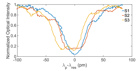
The photon pair generation source is designed with two pulley-type waveguides wrapped around the ring, essentially establishing two unbalanced MZIs. The ring has a radius of 15 m and a coupling gap of 250 m (200 m) at the input (output) side. The length difference of the unbalanced MZI1 (MZI2) is 47.8 m (48 m) and its sinusoidal spectrum determines the wavelength of the constructive and destructive interference. Supplementary Figure 2 shows the pump resonance transmission spectra of source1 (S1), source2 (S2) and source3 (S3) with full widths at half maximum of 44 pm, 50 pm and 53 pm. The resonance splitting of S2 and S3 are due to surface-roughness-induced backscattering Bogaerts et al. (2012).
To pump the sources, laser pulses are produced by a tunable picosecond fibre laser at 1552.02 nm (pulse duration of 7.8 ps, repetition rate of 60.2 MHz, and average power of -0.8 dBm). Before coupling the pump pulse into the chip, the unwanted amplified spontaneous emission (ASE) noise of the pump is filtered by a WDM (extinction ratio of 40 dB and a bandwidth of 1.2 nm) and the polarization of the pump is optimized for maximum fibre-to-chip coupling by a polarization controller (PC). A 32-channel V groove fibre array with a spacing of 127 m and polishing angle of is used to couple the light via transverse electric (TE) grating couplers into the chip. The FSR of the source is approximately 6.2 nm. Entangled photons emerging from the chip are filtered by off-chip single-channel WDMs to remove the residual pump and are finally detected by six superconducting nanowire single photon detectors (SSPD) with 80% detection efficiency, 100 Hz dark count rates, a 50 ns dead time and a 100 ps timing jitter. The losses for the photons in the path entanglement measurement add up to 18.73 dB 19.13 dB, which can be decomposed as follows: the total fibre-chip-fibre loss is 15.56 dB (measured by launching non-resonance light of 1 mW and collecting the output power at the through port of the source), the insertion losses over the full band of the off-chip WDMs are 2-2.4 dB, and the detection losses are 0.97 dB. The detector electrical signals are collected by a field-programmable gate array (FPGA)-based timetag device. All the heaters are independently controlled by a programmable current source with a range of 0-20 mA and 16-bit resolution.
Crosstalk

Mitigating the electrical and thermal crosstalk within hundreds of micrometres is one of the main challenges in our experiment. The relative distances between each component are shown in Supplementary Figure 3a. To reduce the number of electrical pads, we designed all the heaters to have a common ground. However, the resistance between the common ground and true ground is not necessarily zero due to the electrical crosstalk. There are several ways to effectively avoid this effect such as a pre-processing method Carolan et al. (2015), a passive compensation method Paesani et al. (2017), a negative feedback scheme Silverstone et al. (2015), equipping each heater with two separate pads (one for the signal and one for the ground) and using current output equipment Qiang et al. (2018). We tried to use negative feedback to minimize the electrical crosstalk effect. However, as the number of heaters working simultaneously increases, it becomes increasingly difficult to optimize the feedback system to the precision. As shown in Supplementary Figure 3b, we measure the pump transmission spectrum of source 1 (S1) from the input port to the through port of the resonator with and without applying voltages to the other heaters. We choose two heaters ( and ) with approximately equal resistances. When the voltage (4.303 V) is applied to or , a common ground voltage () arises due to the resulting current passing through the contact resistance between the on-chip gold pad and wire-bonded contacts. The effective voltages (heating power) applied to the source are then reduced, resulting in a smaller effective refractive index () change of the waveguide. The change in as a function of temperature can be expressed as , where is the thermo-optic coefficient and is the change in temperature. The thermal-optic coefficient of silicon at 300 K near 1550 nm is Harris et al. (2014). Optical resonances in a resonator require that the optical length (L, where L is the round-trip length) is a multiple of the wavelength of the light. Hence, the reduction in leads to the blueshift of the resonance wavelength. In Supplementary Figure 3b, the resonance wavelength blueshifts 15 pm when the voltage is applied to or . The two approximately equal resistances with the same applied voltages provide similar electrical crosstalk, so the blue and green curves in Supplementary Figure 3b overlap well. We finally chose to use the current source, which is suitable for our experiment.
The thermal crosstalk originating from the heat transfer between the thermos-optical PSs also plays an important role. When we adjust the PSs of the WDMs and the multi-port interferometers, the thermal crosstalk poses a significant challenge for the spectral alignment of different sources due to the narrow resonance linewidths of our resonator-based sources. To overcome this challenge, we optimize the heat sink of the chip carrier and the design of the chip. We quantify the thermal crosstalk with and without (W.O.) heating the PSs with different distances to the source. The heating power is set to 20 mW. Supplementary Figure 3c shows that when the distance between the heater and the resonator decreases, there will be an obvious redshift due to the thermal crosstalk. As can be seen from the figure, the resonance of S1 shifts approximately 5 pm when the heater is positioned at a distance of 500 m from S1, while for a distance of 1200 m, there is little influence due to the thermal crosstalk. In our design, we distanced the PS that needs to be adjusted and the nearest source and achieved a desired isolation level. From the interference fringes shown in Fig. 2 in the main text, we note that the heat diffusion from the PSs has little effect on the sources within a power change of 042 mW (2 phase).
Theoretical analysis and experimental characterization of the dual Mach-Zehnder interferometer micro-ring (DMZI-R) source on a chip
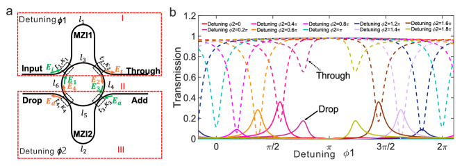
We employ a quadruple-coupler ring resonator with the scheme presented in Supplementary Figure 4a, which is realized by wrapping two pulley waveguides around the input and output sides of the ring Tison et al. (2017). This configuration essentially establishes two unbalanced MZIs, MZI1 and MZI2, out of the waveguides and the ring. AMZI1 (AMZI2) consists of two directional couplers with coupling ratios of k1 and k2 (k3 and k4) and two arms with lengths of l1 and l3 (l2 and l5). For our chip, we set k1=k2 and k3=k4. The radius of the ring is r, while the lengths l4 and l6 are from coupler to coupler. We suppose that the directional couplers have zero length and a wavelength-independent coupling ratio within the wavelength range of interest. If the waveguide lengths are properly chosen, the FSR of the MZIs can be twice that of the ring.
The transmission spectrum of the resonator can be analysed by using a combination of transfer matrices Barbarossa et al. (1995). As shown in Supplementary Figure 4a, the resonators can be divided into two kinds of four-port blocks and two transmission waveguides, labelled as sections , and . For each section, two basic units, the directional coupler and the transmission waveguides, can be expressed in matrix form, relating the input () and output ():
| (6) |
For the directional coupler with a coupling ratio of , the transfer matrix is given as
| (7) |
where i=, and is the amplitude transmission coefficient of the coupler. For transmission waveguides with lengths of and , we can define the transfer matrix as
| (8) |
where is the waveguide transmission loss coefficient and is the propagation constant. Hence, we derive the transfer matrix for the cascaded components in section as
| (9) |
which gives
| (10) |
The same formulas can be used to derive the transfer matrix for section , which relates the two input-output pairs (,) and (, )
| (11) |
where
| (12) |
The cascade of two-pair systems, section and section , involves recirculating light; it is feasible to use a chain matrix G to combine the input-output pairs as
| (13) |
and
| (14) |
where the elements of G can be derived from the transfer matrix H by the following conversion formulas Moslehi et al. (1984)
| (15) |
Moreover, the relation between (,) and (,) in section is only related to the transmission lengths and ,
| (16) |
Substituting Eqs. - in Eq. , one can relate the mixed input-output pairs and as
| (17) |
where
| (18) |
Finally, the transfer matrix from the input pair to the output pair can be determined from the elements of the chain matrix by using the following formulas:
| (19) |
By considering =0, the transmittance characteristics can be obtained as
| (20) |
and
| (21) |
where, with (i=1,2,3,4,5,6). It can be seen from Eqs. and that the phase term has a critical influence on the resonator transmission characteristics. Without loss of generality, we assume that the four phase terms for the ring are equal (). There are four distinct closed loops within the resonator, and the imposed resonance conditions for the round-trip phase delays are
| (22) |
Theoretical calculations of the pump transmittance characteristic of the DMZI-R with and a radius of 15 m are shown in Supplementary Figure 4b versus the detuning phase of AMZI1 for different detuning phases of AMZI2, where and . The length difference of the AMZI1 (AMZI2) is 47.8 m (48 m), corresponding to the nominally designed parameters of our chip. The input (output) side directional coupler amplitude coupling ratio is set to in the absence of coupling loss (=1). It can be seen from this figure that the phase matching conditions rely on the interference pattern of the input and output MZIs. At the input side ensures that the pump laser couples into the resonator, while at the output side minimizes the pump leakage from the drop port and hence maintains the pump within the ring and isolates the ring from photons exiting via the drop port. The phase matching conditions for the generated photons (signal and idler) in the ring are exactly opposite.
The tunable relative phase between the different paths can be realized by the PSs in our device. By appropriately choosing the coupling ratio of the directional coupler and applying heaters to the device, one can effectively achieve critical coupling for the pump photon and over-coupling for both the signal and idler photons.

Supplementary Figure 5 shows the transmission spectra of S1 from the add port to the drop port and from the input port to the through port before (a and b) and after (c and d) optimizing the heaters. From a comparison of Supplementary Figure 5a and 5c, we have enhanced the transmission from the add port to the drop port by tuning the phase of MZI2. Due to the complementary nature of the two-mode MZI, we can minimize the pump (indicated by ”pump” in the figure) leakage from the ring into the drop port and hence maintain the pump within the ring for efficient SFWM. Moreover, at the wavelengths of the signal and idler photons (indicated with red and blue letters), the transmission increases; hence, the extraction efficiency of the correlated photon pair is also enhanced. On the other hand, from a comparison of Supplementary Figure 5b and 5d, by tuning the phase of MZI1, we reduce the transmission of the pump from the input port into the through port and hence maintain the pump within the ring for efficient SFWM. This design can greatly enhance the generation and extraction efficiency of the photon pairs simultaneously and reduce the amount of filtering needed for the pump. In addition, the design can also reduce the spurious SFWM pairs generated in the input waveguide if the coupler to the source is long and further improve the signal-to-noise ratio.
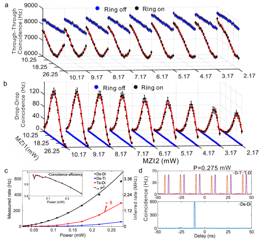
According to the optimum heater configuration that exhibits the desired spectral dependence shown in Supplementary Figure 5, we characterize the coincidence counts of S1 in detail. Supplementary Figure 6a shows the through-through (T-T) coincidence results upon performing a 2-D sweep of the current across the heaters above MZI1 and MZI2 for the on-resonance (black dots) and off-resonance (blue dots) cases, respectively. The average pump power is set to be 0.13 mW before coupling into the chip. We find that in the off-resonance case, the coincidence counts of T-T do not change with the modulation currents. The high rate in the off-resonance case is a result of broadband SFWM in the input bus waveguide, which will be discussed in the following paragraphs. On resonance, the coincidence counts strongly depend on the settings of MZI1 and MZI2 mainly because some of the pump light is coupled into the ring, resulting in less photon pair generation in the straight waveguide. In addition, the T-T coincidence counts cannot be reduced to zero because the photon pairs generated in the input waveguide before the source will be completely outcoupled from the through port when MZI1 is tuned to only support the pump photon at the input side. The drop-drop (D-D) coincidence counts are shown in Supplementary Figure 6b. Off-resonance, D-D dose not show a coincidence count since the pump is not coupled into the ring. For the on-resonance case, as the scan current gradually approaches the optimal configurations, the coincidence counts constantly increase, which complements the on-resonance case of T-T compared to Supplementary Figure 6a. Supplementary Figure 6c illustrates the coincidence counts of Ds-Di, Ds-Ti and Ts-Di as a function of the average pump power. The D-D coincidence rate increases with power, because the efficiency of SFWM scales quadratically with the pump power. The measured rate is 570 Hz at a pump power of 0.275 mW. Taking into account the losses of each photon (fibre-chip-fibre losses of 15.56 dB, insertion losses of the off-chip WDMs of 2.2 dB, and detection losses of 0.97 dB), the inferred generation rate is approximately 3.2 MHz in the resonator. The inset of Supplementary Figure 6c shows that the coincidence efficiency changes with the average pump power. To remove the effect of the photon generation from the input waveguide, we only use the drop port coincidences Ds-Di and split coincidences Ds-Ti and Ts-Di to deduce the coincidence efficiency Tison et al. (2017):
| (23) |
As shown in the inset, in the case of low pump power, the coincidence efficiency is 0.97; however, as the power increases, i.e., as the coincidence rate of Ds-Ti and Ts-Di increases, the efficiency gradually decreases, which results from the accidental rate as shown in Supplementary Figure 6d. All the peaks in the histogram of the Ds-Ti and Ts-Di coincidences are similar, while in the case of D-D, the accidental peaks are almost not visible compared to the main peak. The peaks with a time interval of 16 correspond to the simultaneous detection of photons from different pump pulses.
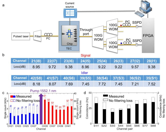
To illustrate the broadband SFWM in the bus waveguide, we measure the continuous emission spectra for the signal and idler photons with the currents set to the on-resonance conditions. In the experimental setup shown in Supplementary Figure 7a, a pulsed laser with an average power of 0.13 mW is first filtered by 200 GHz cascade dense WDM (DWDM) filters to remove the background noise and then is coupled into the chip. Photon pairs are generated from the chip through SFWM, and the photons coupling out from the chip are filtered by a multi-channel 100 GHz DWDM. Supplementary Figure 7c shows the single-count rates for different channels, with a maximum wavelength interval from the pump of approximately 8.5 nm. The rates without filtering loss are inferred based on the independently measured insertion losses for each channel shown in Supplementary Figure 7b. The differences in the single-count rates mainly arise from the Raman scattering of the signal and idler channels. The coincidence rates of the channel pairs are recorded and shown in Supplementary Figure 7d. It is clear that the spectrum of the SFWM in the input waveguide is substantially wider than that of the resonance-matched DMZI-R.
Optimization of two-qubit entanglement
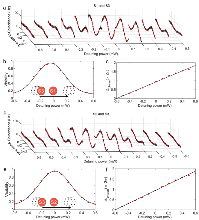
Supplementary Figure 8a to 8c show the two-qubit correlation curves with variations in the interference fringes, i.e., visibilities (b), and phase variations (c) between the different interference curves as a function of the S3-to-S1 detuning. Supplementary Figure 8d to 8f show the corresponding results of the S3-to-S2 detuning. To maintain the matching conditions between MZI1, MZI2 and the ring, we simultaneously change the three heaters on the scanned source with a step of 0.1 mW. It is clear that when the sources are largely detuned, no obvious interference occurs. As the spectra of the sources gradually match, clear interference patterns can be observed. In Supplementary Figure 8c and 8f, the phase variations between the different interference curves are almost linear with approximately the same dependence on the source scanning power, approximately . Therefore, if there is non-negligible thermal or electrical crosstalk mismatching the spectra of the sources, the initial phase of the interference curves will change.
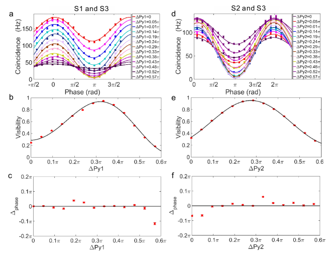
In Supplementary Figure 9, the fringes, visibilities and phase variations between the different path correlation curves for S1 and S3 (a-c) and S2 and S3 (d-f) are plotted for different pump power splittings between the sources while setting the sources detuning power to 0. The step of the heating power applied to or is 1 mW, and the phase change is approximately 0.048. As can be seen from a and d, the interference curves exhibit a significant dependence on the balance of the photon-pair emission between the sources, which can be used to control the amplitude between the components of the output state to prepare variably entangled states. When a maximally entangled state is produced, the maximum visibility can be observed in b and e (94.72%0.50% for S1 and S3, 96.10%0.40% for S2 and S3, respectively). It is also worth noting that the phase variations shown in c and f nearly do not change as the balance changes, indicating that the scanned PS has little impact on the resonator-based sources, since changes in the spectra overlap, i.e., resonance shifts between the sources can introduce a relative phase between the two-qubit state, as shown in Supplementary Figure 8. This shows that the electrical and thermal crosstalk are effectively isolated.
Two-qutrit correlation space
Generally, for a two-qutrit system, the entangled state can be written as
| (24) |
A complete characterization of the higher-order two-qutrit correlations can be realized by using two three-dimensional multiports (3D-MPs). After each qutrit enters the 3D-MP, the state is transformed by a local unitary transformation ():
| (25) |
Then, the resulting state can be written as
| (26) | ||||
The probabilities of detecting a photon pair for different detector combinations are:
| (27) |
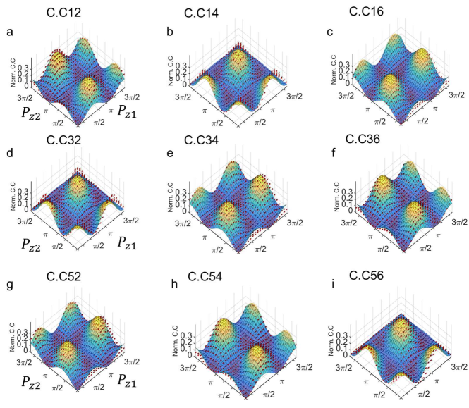
In the experiment, we set and adjust the relative pump phase over S1 and S2 to characterize the high-order Einstein-Podolsky-Rosen (EPR) correlations. All nine output combinations of the coincidences and their respective theoretical results are shown in Supplementary Figure 10. Due to the symmetry of the multi-mode interferometers, three probabilities of equal values are observed. For each pattern, there are three repeated results for each correlation pattern, and the experimental results are in good agreement with the theoretical results.
Supplementary References
References
- Bogaerts et al. (2012) W. Bogaerts, P. De Heyn, T. Van Vaerenbergh, K. De Vos, S. Kumar Selvaraja, T. Claes, P. Dumon, P. Bienstman, D. Van Thourhout, and R. Baets, Laser Photonics Rev. 6, 47 (2012).
- Carolan et al. (2015) J. Carolan, C. Harrold, C. Sparrow, E. Martín-López, N. J. Russell, J. W. Silverstone, P. J. Shadbolt, N. Matsuda, M. Oguma, M. Itoh, et al., Science 349, 711 (2015).
- Paesani et al. (2017) S. Paesani, A. A. Gentile, R. Santagati, J. Wang, N. Wiebe, D. P. Tew, J. L. O Brien, and M. G. Thompson, Phys. Rev. Lett. 118, 100503 (2017).
- Silverstone et al. (2015) J. W. Silverstone, R. Santagati, D. Bonneau, M. J. Strain, M. Sorel, J. L. O Brien, and M. G. Thompson, Nat. Commun. 6, 7948 (2015).
- Qiang et al. (2018) X. Qiang, X. Zhou, J. Wang, C. M. Wilkes, T. Loke, S. O Gara, L. Kling, G. D. Marshall, R. Santagati, T. C. Ralph, et al., Nat. Photon. 12, 534 (2018).
- Harris et al. (2014) N. C. Harris, Y. Ma, J. Mower, T. Baehr-Jones, D. Englund, M. Hochberg, and C. Galland, Opt. Express 22, 10487 (2014).
- Tison et al. (2017) C. Tison, J. Steidle, M. Fanto, Z. Wang, N. Mogent, A. Rizzo, S. Preble, and P. Alsing, Opt. Express 25, 33088 (2017).
- Barbarossa et al. (1995) G. Barbarossa, A. M. Matteo, and M. N. Armenise, IEEE J. Lightwave Technol. 13, 148 (1995).
- Moslehi et al. (1984) B. Moslehi, J. W. Goodman, M. Tur, and H. J. Shaw, Proc. IEEE 72, 909 (1984).