Interface reflectivity of a superdiffusive spin current in ultrafast demagnetization and THz emission
Abstract
The spin- and energy-dependent interface reflectivity of a ferromagnetic (FM) film in contact with a nonmagnetic (NM) film is calculated using a first-principles transport method and incorporated into the superdiffusive spin transport model to study the femtosecond laser-induced ultrafast demagnetization of FeNM and NiNM (NM= Au, Al & Pt) bilayers. By comparing the calculated demagnetization with transparent and real interfaces, we demonstrate that the spin-dependent reflection of hot electrons has a noticeable influence on the ultrafast demagnetization and the associated terahertz electromagnetic radiation. In particular, a spin filtering effect is found at the FeNM interface that increases the spin current injected into the NM metal, which enhances both the resulting demagnetization and the resulting THz emission. This suggests that the THz radiation can be optimized by tailoring the interface, indicating a very large tunability.
I Introduction
In spintronics, the transport properties of electrons can be controlled using magnetic configurations, which determine the local potentials of conduction electrons depending on their spins. Grunberg1988 ; Fert1988 ; wolf2001spintronics The reciprocal process suggests that the local magnetization can be manipulated by a spin-dependent charge current or a pure spin current via the so-called spin-transfer torque.berger1996emission ; slonczewski1996current The magnetization dynamics induced by a spin-transfer torque or an external magnetic field are usually on the time scale of nanoseconds or in the gigahertz regime, which has been well described by the phenomenological Landau-Lifshitz-Gilbert equation gilbert1955lagrangian in the past half century.
The above understanding of magnetization dynamics was challenged by the discovery of the laser-induced magnetization variation in the ferromagnetic metal Ni within hundreds of femtoseconds, which was first observed in a time resolved magneto-optical Kerr effect experiment. beaurepaire1996ultrafast The ultrafast demagnetization was later confirmed via other experimental techniques, such as second harmonic generation,hohlfeld1997nonequilibrium and two-photon photoemission.scholl1997ultrafast One of the key puzzles in this phenomenon is the unknown mechanism that dissipates the spin angular momentum on such a short time scale, regensburger2000time ; koopmans2000ultrafast ; oppeneer2004ultrafast which has stimulated more experimental studies. By means of element-resolved x-ray magnetic circular dichroism, Stamm et al. unambiguously demonstrated that electron orbitals were not the dissipation channel for spin angular momentum. stamm2007femtosecond A spin-polarized charge current was observed during the ultrafast demagnetization, indicating that the spin-dependent transport provided the ultrafast mechanism to transfer spin angular momentum. malinowski2008control ; melnikov2011ultrafast
In the past two decades, much effort has been made to improve the theoretical understanding and description of the ultrafast demagnetization. Beaurepaire et al. beaurepaire1996ultrafast first applied a phenomenological three-temperature model that takes into account the interactions of the electron, spin, and lattice. Later, many physical mechanisms based on local spin flip were proposed to explain the ultrafast dissipation of spin angular momentum. koopmans2005unifying ; carpene2008dynamics ; krauss2009ultrafast ; bigot2009coherent ; lefkidis2009angular ; koopmans2010explaining ; zhang2000laser ; fahnle2011electron More recently, spin-dependent hot-electron transport was proposed to be the main mechanism for ultrafast dissipation of spin angular momentum. battiato2010superdiffusive These models, such as the superdiffusive spin transport model battiato2010superdiffusive ; battiato2012theory and the Boltzmann transport theory based on particle-in-cell simulation, nenno2018particle capture the main physical process of the laser-induced ultrafast demagnetization.
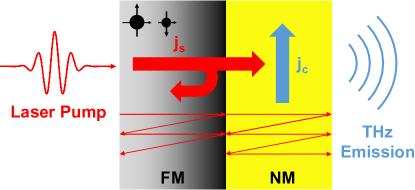
If the FM metal is attached to an NM metal, then the laser-excited hot electrons can transport across the interface and enter the NM metal. The resulting femtosecond pulse of a spin-polarized charge current in the NM metal can be converted to a transverse charge current via the inverse spin Hall effect, valenzuela2006direct ; saitoh2006conversion which in turn generates terahertz electromagnetic emission;kampfrath2013terahertz see Fig. 1. The magnetic multilayers become an effective THz source with the advantages of structural compactness, low cost, flexibility and broadband. seifert2016efficient ; feng2018highly ; herapath2019impact ; nenno2019modification
In the current theory of superdiffusive spin transport, which is applied in the description of both ultrafast demagnetization and THz emission, the FMNM interface is usually assumed to be practically transparent, indicating that all electrons can freely pass through the interface from either side. In reality, the laser-excited hot electrons experience different lattice potentials on the two sides of the interface and therefore are partly reflected, resulting in the so-called interface resistance schep1997interface . Unlike the conventional interface resistance, which is a measure of the reflectivity of conduction electrons at the Fermi level, one needs to consider the reflectivity of the hot electrons at energies higher than the Fermi energy. The interface reflection of an ultrafast spin current was proposed and formulated in detail, battiato2014treating and model transmission of electrons across an interface was studied. rudolf2012ultrafast ; kampfrath2013terahertz Without a quantitative estimation of the energy- and spin-dependent reflectivity of real interfaces, it is difficult to examine the influence of interface reflection on ultrafast demagnetization and terahertz emission based on the theoretical superdiffusive spin transport model. rudolf2012ultrafast ; eschenlohr2013ultrafast ; kampfrath2013terahertz
In this article, we extend superdiffusive spin transport theory to take into account the real reflectivity at the FMNM interface, which is calculated using a first-principles transport method based on the local spin density approximation of density-functional theory. The calculated spin- and energy-dependent reflectivities are then incorporated into the calculation of the superdiffusive spin current. battiato2014treating Using Au, Al, and Pt as typical examples of an NM metal, we explicitly calculate the laser-induced ultrafast demagnetization and THz emission for FeNM and NiNM bilayers. The difference in the calculated results between the transparent and real interface is systematically illustrated. In particular, the FeNM interface exhibits a lower reflectivity for the spin-up electrons than for the spin-down electrons. Such spin filtering effects at the interface effectively increase the spin current injected into the NM metal and therefore enhance the demagnetization and THz emission. The methods presented in this paper can be straightforwardly applied in studying multilayer structures with multiple interfaces, such as spin valves. balavz2018transport The rest of this paper is organized as follows. The first-principles calculation of the interfacial reflectivity is presented in Sec. II. The generalized superdiffusive spin transport theory is given in Sec. III, followed by the calculated ultrafast demagnetization of the FeNM and NiNM bilayers. Section IV shows the THz emission calculated using the real reflectivity of the FMNM interface. The conclusions are drawn in Sec. V.
II Spin- and Energy-Dependent Interface Reflectivity
II.1 Theoretical Methods and Computational Details
With the aim of obtaining the spin- and energy-dependent reflectivity due to interface scattering, we employ a well-developed transport theory based on the Landauer-Büttiker formalism combined with the detailed electronic structure of the real materials obtained from a first-principles calculation xia2001interface . Without introducing any free parameters, this method can be used to calculate the finite-temperature resistivity of transition metals Liu:prb15 and the interface resistance between two metals Xia:prb06 , in good agreement with experiments. The transport calculation is generalized from the Fermi level for quasi-equilibrium states to higher energies to describe the electron and/or spin transport due to excitation by a laser pulse. We present the theoretical and numerical details of our calculation in this section.
First, we define the terminology used in this paper. A “transparent” interface refers to the interface with zero reflectivity. For the real interfaces, whose reflectivity is calculated using first-principles method, we consider clean and disordered interfaces, respectively. The “clean” interface is modeled with a sharp planar boundary between two materials while the “disordered” one has atomic interdiffusion resulting in thin alloying layers at the interface.
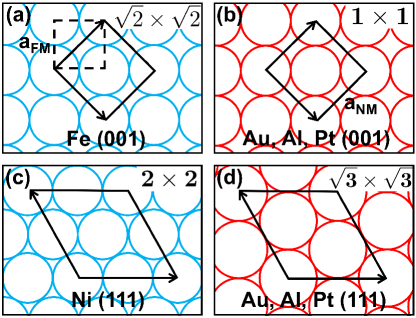
To model the interface between FM (Fe and Ni) and NM metals (Au, Al, and Pt) whose lattices are not matched, we construct periodic supercells in the directions transverse to the transport direction, as schematically illustrated in Fig. 2. The lattice constants of face-centered cubic (FCC) Au ( Å) and Al ( Å) are approximately equal to , where Å is the lattice constant of body-centered cubic (BCC) Fe. Thus, the two-dimensional (2D) Au(001) and Al(001) unit cells are perfectly matched with the supercell of Fe(001), as plotted in Fig. 2(a) and (b). The lattice constant of FCC Pt is slightly smaller than , and thus, we either stretch Pt or compress Fe to make a lattice-matched interface. In practice, the calculated interface reflectivity varies by less than 10% between the two cases. Analogously, we use a Ni(111) supercell to match the NM(111) cell and construct the NiNM(111) interfaces, as shown in Fig. 2(c) and (d). Unless stated otherwise, all the results reported in this paper are carried out with the lattice constants of Å and Å unchanged.
The constructed interfaces are connected to the semi-infinite FM and NM metals on both sides. Within the framework of density functional theory, the electronic structure of the interface is self-consistently determined in the atomic-sphere approximation using the surface Green’s function method turek2013electronic implemented with a tight-binding linear muffin-tin orbital (TB-LMTO) basis Andersen1985 . A minimal basis consisting of , and orbitals is used, and the 2D Brillouin zone is sampled by a mesh with a constant density corresponding to for a FM unit cell.
Having the self-consistent atomic potentials of such interfaces, we solve the quantum scattering problem using a wave-function matching method, which is also implemented using the TB-LMTO basis. Note that the interface resistance arises mainly from the different potentials experienced by conduction electrons across the interface, kritithesis which is of the order of the exchange splitting energy and/or the difference in the work functions of the two metals. Such an energy scale is much larger than that of spin-orbit coupling. Therefore, spin-orbit coupling can be neglected and for each spin channel , all of the propagating Bloch states at every and energy in the FM or NM lead are explicitly calculated. The Sharvin conductance of the material is then determined by the total number of propagating states ,
| (1) |
Here, is the quantized electronic conductance for a single spin channel, is the total number of in the 2D Brillouin zone and is the cross-sectional area of the lateral supercell in the calculation. Note that the NM metal has equal Sharvin conductances for both spin channels, i.e., .
Then, the spin-dependent transmission probability amplitude from the -th propagating state incoming from the left lead to the -th outgoing state in the right lead is evaluated at energy such that the interface conductance is datta1997electronic
| (2) |
Then, we define the spin-dependent interface reflectivity from the FM and NM sides, respectively, as Gijs1997perpendicular
| (3) |
and
| (4) |
Note that although the conductance is invariant for electrons incoming from either side of the interface, the reflectivity can be different owing to the different Sharvin conductances of the FM and NM metals. In addition, for the study of the superdiffusive electron and/or spin transport excited by a laser pulse, we consider the energy range from the Fermi level to 1.5 eV above the Fermi level.
At the metallic interface, the interdiffusion of atoms may result in an interfacial alloy. To model such disordered interfaces, we build a large lateral supercell and randomly distribute two types of atoms in certain interfacial atomic layers consisting of 50%-50% alloy. To ensure accuracy, we take 10 random configurations of the disordered interface for each energy and then average the results. Generally, we apply two atomic layers of the alloy at the disordered interface, and the influence of the thickness of the disordered interfacial layers on the interfacial reflectivity is explicitly examined for the FeAu bilayer.
II.2 FeNM Interface
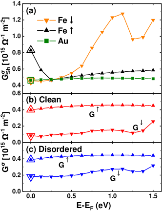
Figure 3(a) shows the calculated Sharvin conductances of Fe and Au as functions of energy. In particular, the Sharvin conductances at the Fermi level are in perfect agreement with those in the literature zwierzycki2005first , which are plotted as large empty symbols for comparison. For Au, the Sharvin conductance exhibits very little energy dependence and is nearly constant (). In contrast, a significant energy dependence is found for the Sharvin conductance of Fe. As the energy increases, first decreases from at the Fermi level to at an energy of 0.25 eV above . This occurs because the number of propagating states becomes smaller at energies above the top of the 3 spin-up bands. This decrease is then followed by a slight increase, where is mostly contributed to by the electrons. For the spin-down electrons, shows a remarkable increase at 0.5 eV above due to the unoccupied 3 bands.
The calculated conductances for clean and disordered FeAu interfaces are plotted in Fig. 3(b) and (c). The spin-up conductances of the clean and disordered interfaces are both approximately m-2 and are independent of the energy, indicating the small effect of the interface disorder on the spin-up conductance. The calculated conductance of the spin-down electrons, which depends slightly on the energy, is increased by the interface disorder. This occurs because the spin-down conducting channels in Fe do not match those of Au in the 2D reciprocal space. Nevertheless, the interface disorder breaks the conservation of momentum and hence increases electron transmission through the interface. xia2001interface
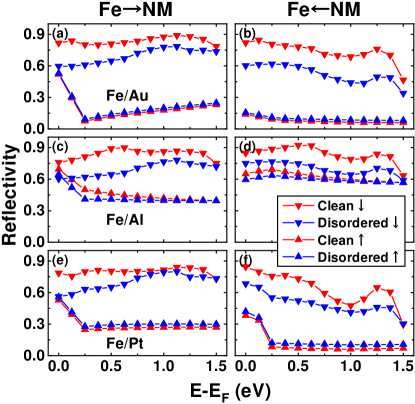
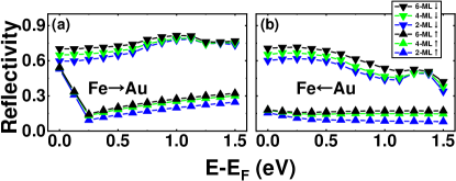
The reflectivity for the FeAu(001) interface can be calculated using Eq. (3) and Eq. (4), as shown in Fig. 4(a) and (b), respectively. For the direction of FeAu, the reflectivities of the spin-up electrons are nearly identical for clean and disordered interfaces. decreases when the energy goes from to eV and slightly increases at higher energy. The energy dependence mainly arises from the energy-dependent Sharvin conductance of Fe . Compared with the spin-up reflectivity, is larger due to the small interface conductance and exhibits a weaker variation as a function of energy. Therefore, the spin-up electrons will pass more easily through the interface from Fe to Au than the spin-down electrons, which is qualitatively consistent with recent calculations. alekhin2017femtosecond The difference in the reflectivity between the two spin channels results in spin filtering for the electrons passing through the FeAu(001) interface.
The calculated reflectivity from Au to Fe is plotted in Fig. 4(b). For spin-up electrons, the reflectivities for clean and disordered interfaces are approximately as small as 0.1. They have minimal energy dependence because both the Sharvin conductance of Au and the spin-up conductance of the FeAu(001) interface do not depend on the energy. For the spin-down electrons, a slight increase in leads to a decrease in the reflectivity, which is particularly prominent near 1.5 eV. The larger for the disordered interface results in a lower reflectivity than in the clean case.
At the real interface, little is known about how deep Fe atoms may diffuse into the Au layer or how thick the interfacial alloy can become. Thus, we model the interfacial alloy at the FeAu(001) interface with two, four and six atomic layers, where the Fe and Au atoms are randomly distributed with equal probability. Here, we consider the same scheme to deal with the different atomic sizes of Fe and Au as in the previous calculation, zwierzycki2005first where the diffused atoms are supposed to occupy atomic spheres of the same size as that of the host element. Then, we repeat the calculation of the interfacial reflectivity, which is plotted in Fig. 5. When the alloy thickness increases from two to six atomic layers, the reflectivity only slightly increases for all the cases, and the reflectivity does not show much dependence on the thickness of the interfacial alloy. Therefore, we use two atomic layers of the alloy to simulate the interface disorder in the following sections of this paper.
The calculated reflectivities of FeAl(001) are displayed in Fig. 4(c) and (d). Similar to the case of FeAu, the spin-down reflectivity from Fe to Al through a clean interface is approximately 0.8 and is slightly lowered by interface disorder. The spin-up reflectivity for FeAl is nearly constant (0.4) from 0.3 eV to 1.5 eV above the Fermi level. Near , the spin-up reflectivity decreases with increasing energy owing to the energy-dependent . In the AlFe direction shown in Fig. 4(d), the spin-up reflectivity is approximately 0.6 for the whole energy range, which is not influenced by interface disorder. The large reflectivity arises from the large Sharvin conductance of Al. The spin-down reflectivities from both sides of FeAl are comparable and are slightly reduced by interface disorder.
For the FePt interface, the calculated reflectivity shown in Fig. 4(e) and (f) shares the main features of FeAu(001). The spin-up reflectivities from both sides are significantly lower than the spin-down reflectivities. In addition, interface disorder slightly lowers the spin-down reflectivity but has little effect on the spin-up reflectivity. The spin-up reflectivities from both sides increase with decreasing energy near the Fermi level, while the spin-down reflectivity from Pt to Fe exhibits a drop at eV.
The calculated spin-down reflectivities for all three cases of FeNM interfaces shown in Fig. 4 are always larger than the reflectivity of the spin-up electrons, independent of the transport direction. This common feature indicates that the FeNM interface plays the role of a spin filter, which improves the spin angular momentum transfer from the Fe layer to the NM layer. We can understand this effect from the electronic structure of the ferromagnetic Fe, whose 3 bands of majority spin are mostly filled and whose 4 electrons dominate the calculated energy range. This can also be seen from the energy independence of the calculated spin-up reflectivity above eV. The electronic structure of all three NM metals, Au, Al, and Pt, are dominated by the electrons (except for Pt) near . The delocalization of the electrons improves the spin-up conductance and hence lowers the spin-up reflectivity. For the minority-spin channel, on the other hand, the presence of the unoccupied electrons of Fe, which are mismatched with the electrons of the NM metal, markedly increases the electron scattering at the interface, resulting in a large spin-down reflectivity. By allowing the transmission from to , interface disorder increases the spin-down conductance. Therefore, the spin-down reflectivity at the disordered interface is slightly lower than that at the clean interface.
II.3 NiNM Interface
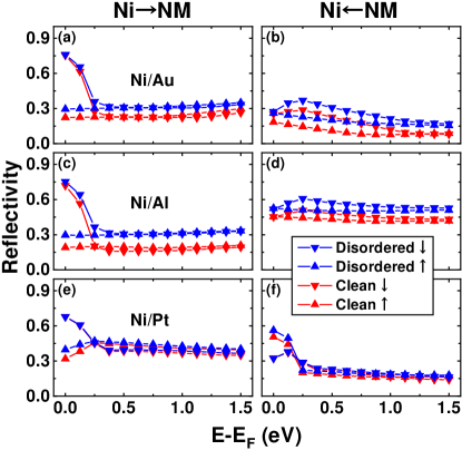
We then calculate the interface reflectivities for NiNM(111) bilayers with NM=Au, Al, and Pt, as shown in Fig. 6, where we find the following two distinct features compared to the reflectivities of FeNM interfaces in Fig. 4: (1) The spin-up and spin-down reflectivities are nearly degenerate in most of the calculated energy range. There is a sharp rise in the spin-down reflectivity from Ni to the NM metal near the Fermi energy. (2) Interface disorder increases the calculated reflectivity for both spin-up and spin-down electrons. These two properties can be understood in terms of the electronic structure of Ni: unlike Fe, the spin-up 3 bands of Ni are fully occupied, and the spin-down 3 bands are mostly occupied. Thus, the electronic structure is dominated by 4 electrons in the energy range we study, except for 3 spin-down electrons near the Fermi level. The latter are responsible for the high spin-down reflectivity of NiNM near the Fermi level, as seen in Fig. 6(a), (c) and (e), indicating that a large fraction of 3 spin-down electrons from Ni do not go through the interface. The calculated reflectivity from Pt to Ni, which is shown in Fig. 6(f), is large near because the 5 electrons are highly reflected at the interface. Because delocalized electrons dominate the transport on both the Ni and NM sides, mismatch in conduction channels in the 2D Brillouin zone, as at the FeAu interface, does not exist. Therefore, interface disorder does not improve the electron transmission through the interface. Instead, the disorder scattering due to the interfacial alloy increases the reflectivity such that the blue symbols in Fig. 6 are always higher than the corresponding red ones. Owing to the comparable reflectivities for spin-up and spin-down electrons, the NiNM interfaces do not act as spin filters, which is significantly different from the FeNM interfaces.
III Ultrafast demagnetization
III.1 The Superdiffusive Spin Transport Model
Superdiffusive spin transport theory has been successfully applied in describing the ultrafast demagnetization resulting from excitation by a femtosecond laser pulse. In this theory, a laser pulse creates many nonequilibrium electrons, which are excited from the occupied states below the Fermi level to the energy bands above . The characteristics of these nonequilibrium electrons, e.g., their group velocities and lifetimes, depend on the magnetic material and the excitation energy. For instance, the majority-spin 3 electrons in Fe are excited to the band by a laser with energy 1.5 eV, while the minority-spin 3 electrons are excited to other unoccupied 3 bands. Therefore, the excited nonequilibrium electrons in Fe have different group velocities depending on their spins. Meanwhile, holes are left in the 3 bands below and are neglected in the superdiffusive spin transport model because of their relatively low mobility. The nonequilibrium electrons above move because of their finite group velocities until they are scattered by phonons, impurities, or other electrons. If the scattering is elastic, then the electrons do not lose energy; however, their momenta are changed by the scattering. Inelastic scattering allows recombination of nonequilibrium electrons with the holes below the Fermi level, where the released energy may excite other electrons to higher energies, giving rise to a cascade of electrons contributing to the transport. Therefore, the electron transport exhibits a ballistic characteristic right after excitation by a laser pulse and gradually approaches the diffusive regime.
The laser-excited superdiffusive spin current can transport across the FMNM interface, which transports angular momentum out of the magnetic material. This outgoing spin current accelerates the ultrafast demagnetization induced by a laser pulse. The spin current injected into the NM heavy metal generates a transverse charge current via the so-called inverse spin-Hall effect (ISHE) Hoffmann:2013 ; Niimi:2015 ; Sinova:2015 and then induces THz emission owing to the sub-picosecond time scale of the charge current. Therefore, the FMNM interface plays an important role in the ultrafast demagnetization and THz emission. In the previous superdiffusive transport model, this interface effect was not systematically examined owing to the lack of reliable electron transmission or reflection data. Here, we include our calculated energy- and spin-dependent electron reflectivity in the superdiffusive transport theory following the treatment in Refs. battiato2010superdiffusive, ; battiato2012theory, ; battiato2014treating, . The main theory is briefly outlined as follows.
Since the laser spot is much larger than the mean free path of the excited hot electrons, this model can be reduced to one dimension, where only the spatial dependence along the interface normal of the metallic multilayers (-axis) is taken into account. The key equation of the superdiffusive spin transport model readsbattiato2010superdiffusive
| (5) |
where is the laser-excited hot electron density with spin at energy , position and time . is the lifetime of hot electrons with spin at energy , and it depends on the material at position . and in Eq. (5) are the electron flux and identity operators, respectively. is the effective source term for the hot electrons including scattered and newly excited electrons. The superdiffusive spin transport equation (5) is non-local in space and time. To solve this integro-differential equation, we adopt a recently developed numerical scheme battiato2014treating and discretize space and time into uniform grids. Explicitly, with the discretized time step , the effective source is written as battiato2012theory
| (6) |
Here, is the transition probability for a hot electron from the state to the state due to scattering, and is the external source of hot electrons that are directly excited by the laser pulse.
The electron flux operator acting on a source term can be explicitly written as
| (7) |
where the spin and energy indices are omitted for simplicity. The flux kernel represents the particle density flux at a given point in space and time resulting from an electron that is excited at and . Specifically, one has
| (8) |
where is the Heaviside step function and the functions are defined as battiato2012theory
| (9) |
and
| (10) |
In the above equations, is the group velocity of hot electrons, which in general depends on the spin , the energy and the material via the position .
The evolution of the spin density in equation (5) is then computed on a discrete spatial grid. The position-dependent reflectivity can be explicitly included in the evolution as
| (11) | |||||
Here, the first term on the right-hand side represents the remaining electron density in the same state that survives any scattering event in the time interval past , and the second term denotes the effective source given in Eq. (6). The other four items correspond to the electron densities flowing into position from both sides through the interface . Note that the spin-dependent electron density is defined on the discrete grid , while the interfaces are chosen in the middle of two neighboring grids, at which the interfacial reflectivity and the electron flux density are defined. battiato2014treating For example, and indicate the electron flux densities flowing to the grid from its left and right sides, respectively. The electron flux density needs to be recursively solved, battiato2014treating
| (12) | |||||
The last two terms on the right-hand sides of the above equations represent the contributions of the incoming electron flux passing through the interface and the reflected outgoing flux for the same interface. Therefore Eq. (12) can recursively compute all the flux densities for the whole space in both directions. In Eq. (12), we introduce an auxiliary integrated flux kernel function [with defined in Eq. (8)],
| (13) |
It is worth emphasizing that we only explicitly include the interfacial reflectivity at the FMNM interface. However, the electron reflection due to scattering occurs everywhere. Inside the same material, the electron reflection is implicitly taken into account by the finite lifetime and the fact that scattering redistributes the energy and momentum of the hot electrons. Here the collision-induced spin flip, which can be a consequence of Elliott-Yafet phonon scattering or an inelastic magnon scattering, is neglected because of their relatively small contribution. carva2011ab ; essert2011electron ; battiato2012theory
In the practical calculation, we need to iteratively solve Eq. (6), Eq. (11) and Eq. (12). Having the electron density and flux density, we are able to obtain the time-dependent magnetization ( is the cross-sectional area)
| (14) |
Here, is the electron density below the Fermi level with spin , and it includes the equilibrium spin-dependent density and the variation due to excitation and decay,
| (15) |
The second term on the right-hand side represents the decrease in occupied electrons owing to the laser excitation, and the last term indicates the increased occupation below due to the hot-electron decay. Note that , where is the thickness of the FM metal.
The occupied electrons have relatively low mobility compared to the excited electrons above , and therefore, their contribution to the spin current is neglected in the superdiffusive spin transport model. The spin current density is defined as the difference between spin-up and spin-down electron flux densities,
| (16) |
The excitation laser pulse is modeled using a Gaussian function with a wavelength of 780 nm (1.5 eV) and a full width at half maximum (FWHM) of 40 fs (60 fs) when calculating the ultrafast demagnetization of Fe (Ni). For Ni, the intensity of the pumped laser is taken as mJ, and 30% of the light is assumed to be absorbed, stamm2007femtosecond corresponding to 0.07 electrons excited per Ni atom. The ratio between the excited spin-up and spin-down electrons is 0.366:0.634. oppeneer2004ultrafast The computational parameters for Fe are the same as in the previous calculation. battiato2012theory The spin-dependent inelastic lifetimes and velocities are taken from first-principles many-body calculations zhukov2005gw+ ; zhukov2006lifetimes . The transition probability function is set to be the same as that in the literature battiato2012theory . Numerically, we use a spatial grid of nm and a time step of fs. The energy range from to eV is considered in the calculation, which is discretized with an energy interval of eV.
It is important to note that the spin-phonon relaxation time and electron-phonon relaxation time are both of the order of several picoseconds koopmans2010explaining ; bigot2000electron corresponding to the increase of the lattice temperature. In this paper, we only calculate the dynamics within several hundreds of femtoseconds corresponding to the process of electron thermalization. Therefore, our treatment with neglecting phonons is valid unless the magnetization dynamics on a larger timescale needs to be studied.
III.2 Ultrafast demagnetization in Fe
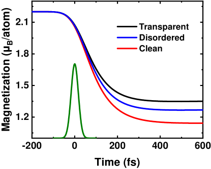
Using the superdiffusive spin transport model, we calculate ultrafast demagnetization in an Fe(10 nm)Au bilayer and plot the magnetization as a function of time in Fig. 7. To model the infinitely thick Au layer, we consider a 40-nm-thick Au film in the practical calculation and set the reflection at its right boundary to be zero. A Gaussian laser pulse with FWHM40 fs is applied as the excitation, as plotted using a green line in Fig. 7. Following the excitation, the magnetization of Fe decreases very rapidly to approximately 50% of its equilibrium .
Compared with the transparent interface used in the literature, the reflectivity of the real interface included in the calculation results in a larger decrease in the ultrafast demagnetization. In the clean interface case, the decrease in magnetization saturates at approximately 1.1 per Fe atom, which is approximately 15% smaller than the value obtained using the transparent interface. The stronger demagnetization occurs because of the spin-dependent interface resistance shown in Fig. 3: the lower reflectivity of spin-up electrons leads to a higher efficiency in transferring the majority-spin angular momentum into the Au layer and therefore enhances the laser-induced demagnetization. The disordered FeAu interface has a weaker spin filter effect than the clean one such that the demagnetization strength is also slightly weaker.
The spin current injected into Au is shown in Fig. 8 for both transparent and clean FeAu interfaces. Owing to the spin filter effect, the spin-up electrons move more easily across the interface, and the resulting spin current, which is injected into Au, is larger than that for the transparent interface. This is in agreement with the stronger demagnetization in Fig. 7.
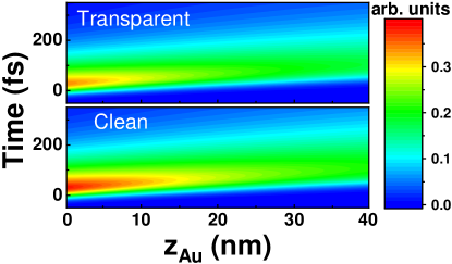
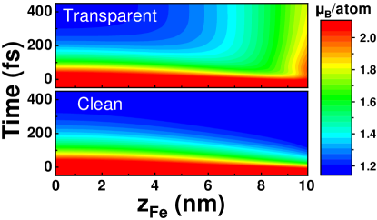
Figure 9 shows the local magnetization variation in the Fe layer after the laser excitation for the transparent and clean FeAu interfaces. Due to the application of the laser pulse, the whole Fe film exhibits significant demagnetization around fs for both the transparent and clean interfaces. The magnetization decrease is stronger on the right side close to the Au layer because, at the FeAu interface, the spin can be transferred into Au, while the left surface of Fe reflects the spins carried by hot electrons. It is interesting to note that spin accumulates at the transparent interface in the upper panel of Fig. 9. Nevertheless, this spin accumulation disappears in the calculation with the real FeAu interface; see the lower panel. Such a difference is responsible for the difference in the ultrafast demagnetization shown in Fig. 7.
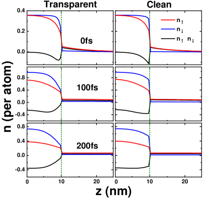
To understand the differences in the interfacial spin accumulation between the transparent and real interfacial reflections, we plot in Fig. 10 the excited spin-dependent electron densities in the FeAu bilayer. The laser pulse excites equal numbers of spin-up and spin-down electrons to energies above the Fermi level in Fe. Because the velocity of spin-up electrons is larger, they exhibit more efficient transport into the Au layer. Thus, the spin-up electron density of Fe (the red lines in Fig. 10) becomes lower than the spin-down electron density (the blue lines). Then, the loss of the majority-spin (spin-up) electrons from the Fe layer results in the demagnetization seen in Fig. 7. With a transparent interface, the high density of spin-down electrons in Fe drives a strong diffusion across the interface into Au, which is more significant than the diffusion of the spin-up electrons. Such a leakage of spin-down electrons leads to the accumulation of spin-up electrons shown in the upper panel of Fig. 9. However, a real FeAu interface has a very high reflectivity for the spin-down electrons. Although the spin-down electron density in Fe near the interface is high, diffusion of these electrons into Au is difficult. On the other hand, the low reflectivity of the interface helps spin-up electrons leave the Fe, removing the spurious spin accumulation due to the transparent interface, as shown in the lower panel of Fig. 9.
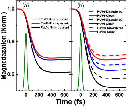
Figure 11(a) shows the calculated demagnetization of a 10-nm-thick Fe film in contact with infinitely thick Au, Al, and Pt layers, where the interface is assumed to be transparent. The FeAu bilayer exhibits the strongest demagnetization, while the demagnetization is comparable in the FeAl and FePt systems. The main factors that determine such differences are the mobility and lifetime of the hot electrons in the NM metal. The hot electrons in Au have the largest group velocity and thus efficiently transfer the spin angular momentum away from the interface, resulting in the ultrafast demagnetization of Fe. The longer lifetime of the hot electrons in Au reduces the electron scattering rate and prevents the injection of spin current back into Fe.
We plot the demagnetization of the Fe film using the real interfacial reflectivity in Fig. 11(b). Unlike the transparent interface, there is a noticeable difference between the FeAl and FePt bilayers. This difference arises because the high reflectivity from Al to Fe [see Fig. 4(d)] strongly suppresses the spin backflow and hence enhances the demagnetization in Fe. For all three NM metals, the spin filter effect is more significant at the clean interface than at the disordered one, and the decrease in magnetization is therefore stronger with the clean FeNM interface. The above numerical results suggest that the interfacial reflectivity plays an important role in the theoretical description of laser-induced ultrafast demagnetization and should not be neglected. The influence of the thickness of the disordered layers is examined using the FeAu bilayer as an example, where the difference in the calculated results is less than 2% for two, four and six atomic layers of the disordered alloy interface.
III.3 Ultrafast demagnetization in Ni
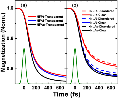
Then, we consider the ultrafast demagnetization of a nickel film of thickness 15 nm that is on top of semi-infinite Au, Al, and Pt layers. Using a transparent interface, the calculated demagnetization is shown in Fig. 12(a). Since the FWHM of the laser is 60 fs, the decrease in magnetization is slower than that in Fig. 11(a). The normalized demagnetization strength is larger for Ni than Fe because the excited hot electrons in Ni are mostly electrons, except for the spin-down channel near the Fermi level. Then, the hot electrons move faster in Ni than those in Fe and can more efficiently transfer the spin angular momentum into the adjacent NM layer. Consistent with the analysis for the FeNM cases, we find that the NiAl and NiPt bilayers are comparable, while the NiAu bilayer has the strongest demagnetization owing to the large mobility and long lifetime of hot electrons in Au.
When taking the real interface reflectivity into account, we see that the demagnetization of NiNM becomes weaker for all three NM metals, in sharp contrast to the cases of FeNM. The interfacial reflectivities shown in Fig. 6 are nearly spin independent for the NiNM systems, unlike the spin filtering at the FeNM interfaces. Compared with the transparent interface, the real interface simultaneously decreases the transmission of spin-up and spin-down electrons. Thus, the efficiency of transferring spin angular momentum from Ni to the NM metals is weaker with the real interfacial reflectivity. As seen in Fig. 6, the alloy disorder at the NiNM interface only plays a minor role in its reflectivity. Thus, the calculated demagnetization of the NiNM bilayer is comparable between the clean and disordered interfaces. In addition, the real NiAl interface exhibits a substantial reflectivity from Al to Ni, which remarkably suppresses flow of the transferred spin current in Al back into Ni. Therefore, the demagnetization of the NiAl bilayer is substantially stronger than that in the NiPt system, although they are comparable in the presence of a transparent interface.
IV THz emission
The spin current carried by the laser-driven hot electrons flowing into the NM metal can generate a transverse charge current via the ISHE Hoffmann:2013 ; Niimi:2015 ; Sinova:2015
| (17) |
where and are the charge and spin current densities, respectively, and represents the polarization of . The charge-spin conversion efficiency is given by the dimensionless parameter , which is usually called the spin Hall angle. Since varies in time, the time-dependent charge current generates electromagnetic waves. In the far-field approximation, the amplitude of the electric field is determined by the time derivative of kuvzel1999spatiotemporal ,
| (18) |
where is the impedance of the bilayer including the contributions from the half space of air and the other half space of the substrateseifert2016efficient , is the terahertz beam waist and here refers to the radius of the laser pulse spot, denotes the distance between the terahertz emitter and the detector, and is the speed of light.
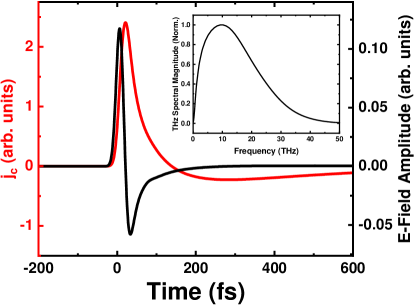
The above computational scheme is illustrated using a Fe(10 nm)Au(15 nm) bilayer. The red line in Fig. 13 shows the average electric current density in Au as a function of time. Here, we only consider the relative strength such that the particular value of the spin Hall angle does not play a role. The electric current pulse exhibits an asymmetric shape: its quick increase at 21 fs results in a large positive peak in the emitted electric field (the black line), while the slow decay at 21 fs gives rise to the smaller negative peak. The width of the electric current pulse is approximately 100 fs, corresponding to the terahertz frequency regime. The spectrum in the frequency domain is obtained by Fourier transform of the emitted electric field, which is plotted in the inset of Fig. 13.
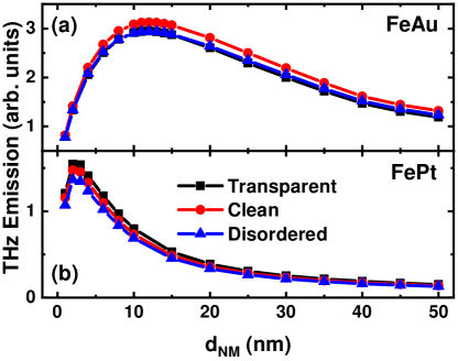
In the following, we use the difference between the maximum and minimum -field amplitudes as a measure of the THz emission strength, which is plotted in Fig. 14(a) as a function of the Au thickness. In general, the THz emission shows a non-monotonic dependence on the Au thickness . At small , the injected spin current is reflected back to Fe before it is fully exploited to generate a transverse charge current such that the THz emission increases with increasing . When the Au layer is thick enough, the total transverse charge current is expected to saturate, while the decrease in the impedance leads to a decrease in the emitted THz amplitude. seifert2016efficient Because the real FeAu interface has a spin filtering effect, including the reflectivity of the real interface increases the spin current injected into Au. Therefore, the calculated THz emission is larger for the clean interface than for the transparent one, as shown in Fig. 14(a). This indicates that the THz emission can be optimized by an effective spin filter at the interface.
Figure 14(b) shows the calculated THz emission of the FePt bilayer as a function of the Pt thickness, which also exhibits a non-monotonic behavior. The maximum value is located at nm and is much smaller than that in the case of FeAu. This occurs because the spin diffusion length of Pt is much shorter than that of Au such that the spin current in Pt is fully converted to the transverse charge current within a very short length scale. It is interesting to note that the emitted electromagnetic field amplitude is smaller for the real interface reflectivity, in contrast to FeAu. Although the real FePt interface reflectivity increases the spin polarization of the current injected into Pt compared to the transparent interface, it decreases the absolute amplitude of the current. Therefore, to increase the THz emission, one should maximize both the amplitude and spin polarization of the current injected into the NM metal.
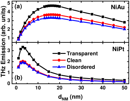
The calculated THz emission amplitudes of the NiAu and NiPt bilayers are plotted in Fig. 15. The thickness of the Ni film is 10 nm. Since the NiAu and NiPt interfaces do not have a spin filter effect, the real interface reflectivity only decreases the total amount of spin current injected into the NM metal, resulting in a weaker emitted electromagnetic field compared with the corresponding transparent interface. In analogy with the FeNM bilayers, the THz emission by the NiNM systems also shows a non-monotonic dependence on the NM thickness. Moreover, the maximum value occurs at a shorter thickness for the NiPt system than for the NiAu system owing to the shorter spin diffusion length of Pt.
In addition to the transverse charge current generated via the ISHE, a tilting magnetization can also generate a charge current at an interface as the inverse effect of spin-orbit torque. In a recent experiment, helicity-dependent in-plane photocurrents are observed at FMNM interfaces due to the Rashba spin-orbit interaction huisman2016femtosecond . This effect results in the THz field parallel to the magnetization of the FM metal while the ISHE leads to the field perpendicular to the magnetization. Moreover, the THz field strength arising from interface Rashba effect is much smaller than the contribution from ISHE and therefore is neglected in this paper.
V Conclusions and discussions
We have calculated the spin- and energy-dependent electron reflectivity at the FMNM interfaces with FM=Fe and Ni and NM=Au, Al, and Pt using first-principles scattering theory. The FeNM interfaces show a spin filtering effect owing to wave function mismatch between spin-dependent electronic states above the Fermi energy. The calculated interface reflectivity is incorporated into the superdiffusive spin transport theory, which is used to study the laser-induced demagnetization and THz emission in FeNM and NiNM heterostructures. The spin filtering effects at the FeNM interfaces enhance the demagnetization and electromagnetic radiation amplitude. Using FeAu as an example, we demonstrate that the spurious spin accumulation in Fe close to the FeAu interface is eliminated by employing the calculated reflectivity of the real interface. For the NiNM bilayers, the calculated demagnetization and THz emission are weaker for the real interface reflectivity because the amplitude of the spin current injected into the NM metal is smaller. These results suggest that the reflectivity of real interfaces has to be taken into account in a quantitative description of laser-induced demagnetization and THz emission.
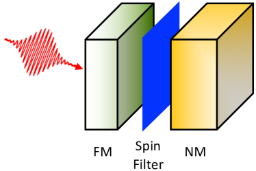
Noting the important role of the interface reflection and transmission allows us to have more flexibility in designing and optimizing spintronic THz emitters. As schematically illustrated in Fig. 16, we propose an efficient spintronic emitter with a coated interface. The main functionality of the FM layer on the left side is to absorb the laser pulse and create as many hot electrons as possible. Therefore, a FM metal or an alloy with a high density of states above the Fermi energy is preferred. The spin filter between the left-hand-side metal and the right-hand-side NM metal can be an FM metal or an alloy, as well as some coating at the interface. This results in large transmission of one spin and small transmission of the opposite spin such that the hot electrons are highly spin-polarized after being injected into the NM metal, which should have a large spin-to-charge conversion efficiency, e.g., a large spin Hall angle, and the radiated THz electromagnetic wave can be maximized. For example, we expect that inserting a very thin Fe layer between Ni and the NM metal could significantly enhance the spin polarization of the hot electrons entering the NM metal. Therefore, the THz emission of the NiFeNM multilayer is expected to be stronger than that of the NiNM bilayer.
Acknowledgements.
We thank T. Kampfrath, C. Stamm, Ka Shen and Luo Zhang for helpful discussions and communications. This work was partly supported by the National Natural Science Foundation of China (Grants No. 61774018 and No. 11734004), the Recruitment Program of Global Youth Experts, and the Fundamental Research Funds for the Central Universities (Grants No. 2018EYT03 and No. 2018STUD03).References
- (1) G. Binasch, P. Grünberg, F. Saurenbach, and W. Zinn, Phys. Rev. B 39, 4828 (1989).
- (2) M. N. Baibich, J. M. Broto, A. Fert, F. Nguyen Van Dau, F. Petroff, P. Etienne, G. Creuzet, A. Friederich, and J. Chazelas, Phys. Rev. Lett. 61, 2472 (1988).
- (3) S. A. Wolf, D. D. Awschalom, R. A. Buhrman, J. M. Daughton, S. von Molnár, M. L. Roukes, A. Y. Chtchelkanova, and D. M. Treger, Science 294, 1488 (2001).
- (4) L. Berger, Phys. Rev. B 54, 9353 (1996).
- (5) J. C. Slonczewski, J. Magn. Magn. Mater. 159, L1 (1996).
- (6) T. L. Gilbert, Phys. Rev. 100, 1243 (1955).
- (7) E. Beaurepaire, J.-C. Merle, A. Daunois, and J.-Y. Bigot, Phys. Rev. Lett. 76, 4250 (1996).
- (8) J. Hohlfeld, E. Matthias, R. Knorren, and K. H. Bennemann, Phys. Rev. Lett. 78, 4861 (1997).
- (9) A. Scholl, L. Baumgarten, R. Jacquemin, and W. Eberhardt, Phys. Rev. Lett. 79, 5146 (1997).
- (10) H. Regensburger, R. Vollmer, and J. Kirschner, Phys. Rev. B 61, 14716 (2000).
- (11) B. Koopmans, M. van Kampen, J. T. Kohlhepp, and W. J. M. de Jonge, Phys. Rev. Lett. 85, 844 (2000).
- (12) P.M. Oppeneer and A. Liebsch, J. Phys.: Condens. Matter 16, 5519 (2004).
- (13) C. Stamm, T. Kachel, N. Pontius, R. Mitzner, T. Quast, K. Holldack, S. Khan, C. Lupulescu, E. F. Aziz, M. Wietstruk, H. A. Dürr, and W. Eberhardt, Nat. Mater. 6, 740 (2007).
- (14) G. Malinowski, F. Dalla Longa, J. H. H. Rietjens, P. V. Paluskar, R. Huijink, H. J. M. Swagten, and B. Koopmans, Nat. Phys. 4, 855 (2008).
- (15) A. Melnikov, I. Razdolski, T. O. Wehling, E. Th. Papaioannou, V. Roddatis, P. Fumagalli, O. Aktsipetrov, A. I. Lichtenstein, and U. Bovensiepen, Phys. Rev. Lett. 107, 076601 (2011).
- (16) B. Koopmans, J. J. M. Ruigrok, F. Dalla Longa, and W. J. M. de Jonge, Phys. Rev. Lett. 95, 267207 (2005).
- (17) E. Carpene, E. Mancini, C. Dallera, M. Brenna, E. Puppin, and S. De Silvestri, Phys. Rev. B 78, 174422 (2008).
- (18) M. Krauß, T. Roth, S. Alebrand, D. Steil, M. Cinchetti, M. Aeschlimann, and H. C. Schneider, Phys. Rev. B 80, 180407(R) (2009).
- (19) J.-Y. Bigot, M. Vomir, and E. Beaurepaire, Nat. Phys. 5, 515 (2009).
- (20) G. Lefkidis, G. P. Zhang, and W. Hübner, Phys. Rev. Lett. 103, 217401 (2009).
- (21) B. Koopmans, G. Malinowski, F. Dalla Longa, D. Steiauf, M. Fähnle, T. Roth, M. Cinchetti, and M. Aeschlimann, Nat. Mater. 9, 259 (2010).
- (22) M. Fähnle and C. Illg, J. Phys.: Condens. Matter 23, 493201 (2011).
- (23) G. P. Zhang and W. Hübner, Phys. Rev. Lett. 85, 3025 (2000).
- (24) M. Battiato, K. Carva, and P. M. Oppeneer, Phys. Rev. Lett. 105, 027203 (2010).
- (25) M. Battiato, K. Carva, and P. M. Oppeneer, Phys. Rev. B 86, 024404 (2012).
- (26) D. M. Nenno, B. Rethfeld, and H. C. Schneider, Phys. Rev. B 98, 224416 (2018).
- (27) E. Saitoh, M. Ueda, H. Miyajima, and G. Tatara, Appl. Phys. Lett. 88, 182509 (2006).
- (28) S. O. Valenzuela and M. Tinkham, Nature (London) 442, 176 (2006).
- (29) T. Kampfrath, M. Battiato, P. Maldonado, G. Eilers, J. Nötzold, S. Mährlein, V. Zbarsky, F. Freimuth, Y. Mokrousov, S. Blügel, M. Wolf, I. Radu, P. M. Oppeneer, and M. Münzenberg, Nat. Nanotech. 8, 256 (2013).
- (30) T. Seifert, S. Jaiswal, U. Martens, J. Hannegan, L. Braun, P. Maldonado, F. Freimuth, A. Kronenberg, J. Henrizi, I. Radu, E. Beaurepaire, Y. Mokrousov, P. M. Oppeneer, M. Jourdan, G. Jakob, D. Turchinovich, L. M. Hayden, M. Wolf, M. Münzenberg, M. Kläui, and T. Kampfrath, Nat. Photonics 10, 483 (2016).
- (31) Z. Feng, R. Yu, Y. Zhou, H. Lu, W. Tan, H. Deng, Q. Liu, Z. Zhai, L. Zhu, J. Cai, B. F. Miao, and H. F. Ding, Adv. Opt. Mater. 6, 1800965 (2018).
- (32) R. I. Herapath, S. M. Hornett, T. S. Seifert, G. Jakob, M. Kläui, J. Bertolotti, T. Kampfrath, and E. Hendry, Appl. Phys. Lett. 114, 041107 (2019).
- (33) D. M. Nenno, L. Scheuer, D. Sokoluk, S. Keller, G. Torosyan, A. Brodyanski, J. Lösch, M. Battiato, M. Rahm, R. H. Binder, H. C. Schneider, R. Beigang, and E. Th. Papaioannou, Sci. Rep. 9, 13348 (2019).
- (34) K. M. Schep, J. B. A. N. van Hoof, P. J. Kelly, G. E. W. Bauer, and J. E. Inglesfield, Phys. Rev. B 56, 10805 (1997).
- (35) M. Battiato, P. Maldonado, and P. M. Oppeneer, J. Appl. Phys. 115, 172611 (2014).
- (36) D. Rudolf, C. La-O-Vorakiat, M. Battiato, R. Adam, J. M. Shaw, E. Turgut, P. Maldonado, S. Mathias, P. Grychtol, H. T. Nembach, T. J. Silva, M. Aeschlimann, H. C. Kapteyn, M. M. Murnane, C. M. Schneider, and P. M. Oppeneer, Nat. Commun. 3, 1037 (2012).
- (37) A. Eschenlohr, M. Battiato, P. Maldonado, N. Pontius, T. Kachel, K. Holldack, R. Mitzner, A. Föhlisch, P. M. Oppeneer, and C. Stamm, Nat. Mater. 12, 332 (2013).
- (38) P. Baláž, M. Žonda, K. Carva, P. Maldonado, and P. M. Oppeneer, J. Phys.: Condens. Matter 30, 115801 (2018).
- (39) K. Xia, P. J. Kelly, G. E. W. Bauer, I. Turek, J. Kudrnovský, and V. Drchal, Phys. Rev. B 63, 064407 (2001).
- (40) Y. Liu, Z. Yuan, R. J. H. Wesselink, A. A. Starikov, M. van Schilfgaarde, and P. J. Kelly, Phys. Rev. B 91, 220405(R) (2015).
- (41) P. X. Xu, V. M. Karpan, K. Xia, M. Zwierzycki, I. Marushchenko, and P. J. Kelly, Phys. Rev. B 73, 180402(R) (2006).
- (42) I. Turek, V. Drchal, J. Kudrnovský, M. Šob, and P. Weinberger, Electronic Structure of Disordered Alloys, Surfaces and Interfaces (Kluwer, Boston, 1997).
- (43) O. K. Andersen, O. Jepsen, and D. Glötzel, in Highlights in Condensed Matter Theory, edited by F. Bassani, F. Fumi, and M.P. Tosi (North-Holland, Amsterdam, 1985).
- (44) Kriti Gupta, Ph.D. Thesis, University of Twente, The Netherlands (2019).
- (45) S. Datta, Electronic Transport in Mesoscopic Systems (Cambridge University Press, Cambridge, England, 1995).
- (46) Martin A. M. Gijs and Gerrit E. W. Bauer, Adv. Phys. 46, 285 (1997).
- (47) M. Zwierzycki, Y. Tserkovnyak, P. J. Kelly, A. Brataas, and G. E. W. Bauer, Phys. Rev. B 71, 064420 (2005).
- (48) A. Alekhin, I. Razdolski, N. Ilin, J. P. Meyburg, D. Diesing, V. Roddatis, I. Rungger, M. Stamenova, S. Sanvito, U. Bovensiepen, and A. Melnikov, Phys. Rev. Lett. 119, 017202 (2017).
- (49) A. Hoffmann, IEEE Trans. Magn. 49, 5172 (2013).
- (50) Y. Niimi and Y. Otani, Rep. Prog. Phys. 78, 124501 (2015).
- (51) J. Sinova, S. O. Valenzuela, J. Wunderlich, C. H. Back, and T. Jungwirth, Rev. Mod. Phys. 87, 1213 (2015).
- (52) K. Carva, M. Battiato, and P. M. Oppeneer, Phys. Rev. Lett. 107, 207201 (2011).
- (53) Sven Essert and Hans Christian Schneider, Phys. Rev. B 84, 224405 (2011).
- (54) V. P. Zhukov, E. V. Chulkov, and P. M. Echenique, Phys. Rev. B 73, 125105 (2006).
- (55) V. P. Zhukov, E. V. Chulkov, and P. M. Echenique, Phys. Rev. B 72, 155109 (2005).
- (56) J.-Y. Bigot, V. Halté, J.-C. Merle, A. Daunois, Chem. Phys. 251, 181 (2000).
- (57) P. Kužel, M. A. Khazan, and J. Kroupa, J. Opt. Soc. Am. B 16, 1795 (1999).
- (58) T. J. Huisman, R. V. Mikhaylovskiy, J. D. Costa, F. Freimuth, E. Paz, J. Ventura, P. P. Freitas, S. Blügel, Y. Mokrousov, Th. Rasing, and A. V. Kimel, Nat. Nanotech. 11, 455 (2016).