Optical control of an individual Cr spin in a semiconductor quantum dot
Abstract
Individual localized spins in semiconductors are attracting significant interest in the frame of quantum technologies including quantum information and quantum enhanced sensing. Localized spins of magnetic atoms incorporated in a semiconductor are particularly promising for quantum sensing. Here we demonstrate that the spin of a Cr atom in a quantum dot (QD) can be controlled optically and we discuss the main properties of this single spin system. The photoluminescence of individual Cr-doped QDs and their evolution in magnetic field reveal a large magnetic anisotropy of the Cr spin induced by local strain. This results in a splitting of the Cr spin states and in a thermalization on the lower energy states states Sz=0 and Sz=1. The magneto-optical properties of Cr-doped QDs can be modelled by an effective spin Hamiltonian including the spin to strain coupling and the influence of the QD symmetry. We also show that a single Cr spin can be prepared by resonant optical pumping. Monitoring the intensity of the resonant fluorescence of the QD during this process permits to probe the dynamics of the optical initialization of the spin. Hole-Cr flip-flops induced by an interplay of the hole-Cr exchange interaction and the coupling with acoustic phonons are the main source of relaxation that explains the efficient resonant optical pumping. The Cr spin relaxation time is measured in the range. We evidence that a Cr spin couples to non-equilibrium acoustic phonons generated during the optical excitation inside or near the QD). Finally we show that the energy of any spin state of an individual Cr atom can be independently tuned by a resonant single mode laser through the optical Stark effect. All these properties make Cr-doped QDs very promising for the development of hybrid spin-mechanical systems where a coherent mechanical driving of an individual spin in an oscillator is required.
I Introduction
Individual spins in semiconductors are promising for the development of quantum technologies based on solid state devices. Important progresses have been made recently for spins of carriers confined in nano-structures Veldhorst2015 and for electronic and nuclear spins localized on individual defects Schmitt2017 . Diluted magnetic semiconductor systems combining high quality nano-structures and localized spins on transition metal elements are alternative good candidates for the development of such single spin quantum devices. Optically active quantum dots (QDs) containing individual or pairs of magnetic dopants can be realized both in II-VI Besombes2004 ; Goryca2009 ; LeGall2009 ; LeGall2010 ; LeGall2011 ; Besombes2012 and III-V Kudelski2007 ; Krebs2013 semiconductors. In these systems, since the confined carriers and magnetic atom spins are strongly mixed, an optical excitation of the QD can affect the spin state of the atom offering possibilities for probing and controlling of the localized spin Govorov2005 ; Reiter2013 .
The variety of transition metal magnetic elements that can be incorporated in conventional semiconductors gives a large choice of localized electronic and nuclear spins as well as orbital momentum Besombes2004 ; Kobak2014 ; Smolenski2016 ; Lafuente2016 . For a given semiconductor nano-structure, the spin properties resulting from the exchange interaction between the confined carriers and the incorporated magnetic dopant depend on the filling of the orbital of the atom. The choice of a particular magnetic element can then be adapted for a targeted application. This approach opens a diversity of possible use of individual spins in diluted magnetic semiconductor nano-structures for quantum information technologies or quantum sensing.
Among these magnetic atoms, chromium (Cr) is of particular interest Lafuente2016 . It usually incorporates in intrinsic II-VI semiconductors as Cr2+ carrying an electronic spin S=2 and an orbital momentum L=2. Moreover, most of Cr isotopes have no nuclear spin. This simplifies the spin level structure and the coherent dynamics of its electronic spin Vallin1974 . With bi-axial strain, the ground state of the Cr is expected to be an orbital singlet with a spin degeneracy of 5. The non zero orbital momentum (L=2) of the Cr atom connects its electronic spin to the local strain through the modification of the crystal field and the spin-orbit coupling. This spin to strain coupling is expected to be more than two orders of magnitude larger than for elements without orbital momentum like NV centers in diamond Tessier2014 or Mn atoms in II-VI semiconductors Lafuente2015 .
In analogy with the spin structure of NV centers in diamond, the spin states S of a Cr2+ ion in a QD form a spin coupled to in-plane strain Lee2017 . The Cr spin is therefore promising for the realization of hybrid spin-mechanical systems Pigeau2015 ; Macquarrie2015 in which the motion of a mechanical oscillator would be coherently coupled to the spin state of a single atom and probed or coherently controlled through this interaction Tessier2014 ; Rabl2010 ; Ovar2014 .
This review article is organized as follows: after a short presentation of the spin properties of magnetic atoms in semiconductors and their exchange interaction with the carriers of the host we discuss how we can use the optical properties of a QD to probe the spin of an individual Cr. We show that magneto-optics is an efficient tool to extract the relevant parameters of the QDs and the strength of carriers-Cr exchange interaction. We then present optical techniques for to control the Cr spin (resonant optical pumping and energy tuning by optical Stark effect) and discuss the dynamics of Cr spin in the presence of optically created carriers or in the dark. We finally show that Cr atoms in a QD forms an interesting platform for the study of the coupling of individual spins with propagating surface acoustic phonons which are proposed as efficient quantum bus between different kinds of qubits Schuetz2015 .
II Spin properties of magnetic atoms in semiconductors
The important properties of individual magnetic atoms in diluted magnetic semiconductors arise from (i) their fine (and hyperfine) structure, which controls the spin dynamics at zero or weak magnetic field and (ii) the exchange interaction with the carriers of the host, which determines the conditions of optical and electrical control. We will discuss here the origin of these two parameters for Cr embedded in CdTe/ZnTe QDs and compare with more extensively studied Mn-doped systems.
II.1 Fine and hyperfine structure of a magnetic atom in a II-VI semiconductor
Cr atoms are usually incorporated into un-doped II-VI semiconductors as Cr2+ ions on cation sites forming a deep impurity level. The ground state of a free Cr2+ is 5D with the orbital quantum number L=2 and a spin S=2 yielding a 25-fold degeneracy. In the crystal field of Td symmetry of the tetrahedral cation site in zinc-blende crystal, the degeneracy is partially lifted (see Figure 1): the 5D term splits into 15-fold degenerate orbital triplet 5T2 and 10-fold degenerate orbital doublet 5E. The Jahn-Teller distortion reduces the symmetry to D2d and leads to a splitting of the 5T2 ground state into a 5-fold degenerate 5B2 orbital singlet and a 5E orbital doublet.
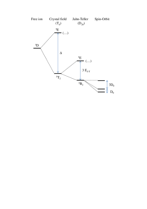
The ground state orbital singlet 5B2 is further split by the spin-orbit interaction. In a strain free crystal, it was found that the ground state splitting can be described by the spin effective Hamiltonian Vallin1974 :
| (1) |
with , . For the studies reported here, it is a good approximation to take and . The x, y, z principal axes were found to coincide with the cubic axes (1,2,3) giving rise to three identical sites, each given by (1) but with the z axis of each along a different cubic axis (1,2,3). A value of was estimated from Electron Paramagnetic Resonance (EPR) measurements in highly diluted bulk Cr-doped CdTe Vallin1974 .
Static biaxial compressive strain in the (001) plane, as observed in self-assembled QDs, reduces the symmetry to D2d and destabilize the Cr orbitals and having an electron density pointing along the 001 axis ( axis). The Cr ground state is then a 5-fold spin degenerated orbital singlet formed from the orbital. It corresponds to the Jahn-Teller ground state with a tetragonal distortion along the 001 axis Brousseau1988 .
An additional applied stress will influence the Cr spin fine structure through the modification of the crystal field and the spin-orbit interaction. For an arbitrary strain tensor, the general form of the Cr ground state spin effective Hamiltonian is Vallin1974
| (2) |
with Si defined as:
| (3) |
and defined similarly as:
| (4) |
where the are components of the strain tensor. For a flat CdTe self-assembled QDs in ZnTe with a dominant in-plane biaxial strain we have a strain tensor:
| (5) |
with and Cij the stiffness constants for CdTe.
| c1 | c2 | c3 | c4 | c5 |
| -0.252 | +4.9 2 | -1.20.5 | +4.92 | +3.71.25 |
For this strain configuration, the Cr fine structure is controlled by the spin-lattice coupling coefficients c1 (symmetric coefficient) and c2 (tetragonal coefficients). The strain-coupling coefficients estimated from EPR measurements in bulk Cr doped CdTe are listed in table 1. The strain controlled part of the spin Hamiltonian becomes:
| (6) |
where we can estimate a magnetic anisotropy D 10.6 meV from the values of the spin to strain coupling coefficients in pure CdTe (table 1) and .
An anisotropy of the strain in the QD plane (001) would affect the Cr fine structure through the tetragonal coefficients c3 and c4. The largest spin to strain coupling is expected for a strain along 110 direction (coefficient ) with and . This interaction can be described by an additional term in the spin-strain Hamiltonian
| (7) |
This anisotropy term couples spin states separated by two units and in particular Sz=+1 and Sz=-1 which are initially degenerated in the absence of magnetic field. As we will see in the last section, such term, together with terms proportional to , can be exploited to induce a strain mediated coherent coupling between a mechanical oscillator and a Cr spin.
The situation is different for a Mn atom which, incorporated as a Mn2+ ion in II-VI compounds, has no orbital momentum. As the ground state of the Mn2+ has no orbital degeneracy it is not affected by the Td crystal field nor by the reduction of its symmetry by biaxial strain. However the spin degeneracy is lifted by a combination of spin-orbit interaction and reduced symmetry of the crystal field. As in the case of Cr this results in a splitting of the spin levels according to but with at least two orders of magnitude weaker than in the Cr case (values around 7 were measured in CdTe/ZnTe QDs Goryca2014 ; Jamet2013 . All the Mn stable isotopes carries a nuclear spin I=5/2. This nuclear spin couples to the electrons via the hyperfine interaction with . The fine and hyperfine splitting have similar values and this results in a complex 36 spin level structure responsible of the rich spin dynamics observed for an individual Mn atom in a QD Goryca2014 ; Jamet2013 .
II.2 Exchange interaction between carriers and a magnetic atom
Diluted magnetic semiconductors are characterised by a large exchange interaction between the localized spins of the magnetic atoms and the carriers of the host. The electron-magnetic atom coupling for carriers at the center of the Brillouin zone arises from the standard short range exchange interaction. It is then ferromagnetic and a value of the exchange energy N (where is the number of unit cell in a normalized volume) is found for most of the transition metals incorporated in wide band gap II-VI compounds Kacman2001 .
The exchange interaction with the hole spin is usually larger than the interaction with the electron spin and arises from two mechanisms: (i) a ferromagnetic coupling resulting from the short range exchange interaction and (ii) a spin dependent hybridization of the orbital of the magnetic atom and the orbital of the host semiconductor, the so-called kinetic exchange.
The hybridization is strongly sensitive to the energy splitting between the levels of the atom and the top of the valence band. This hybridization of course significantly depends on the considered transition metal element (i.e. filling of the orbital) and, for a given magnetic element, on the semiconductor host Kossut . It can be either ferromagnetic or anti-ferromagnetic depending on the relative position of the levels and the top of the valence.
In the case of Mn, the Mn2+/3+ donor level is located far within the valence band and the kinetic exchange results in an anti-ferromagnetic hole-Mn coupling. The p-d hybridization has the main contribution to the hole-Mn exchange and the overall interaction is anti-ferromagnetic. A value of N has been measured for Mn in CdTe Furdyna1988 .
For a Cr atom in the 3 configuration, it has been demonstrated Blinowski1992 ; Kacman2001 that the exchange interaction between a Cr atom with a Jahn-Teller distortion oriented along the [001] axis (z-axis) and a heavy-hole with a component of its total angular momentum Jz=3/2 can be expressed in the form:
| (8) |
where (with N=4 for Cr) is given by
| (9) |
with the unperturbed energy of the shell with N electrons and total spin S, Vpd the hybridization constant between the orbital of the impurity and the orbital of the semiconductor host and the energy of the top of the valence band Kacman2001 . This Cr site orientation along the [001] axis corresponds to the CdTe/ZnTe QDs where a Cr atom can be optically detected. Such dots are characterized by a large biaxial strain which dominates the Jahn-Teller effect and orients the Cr spin along the QD growth axis Brousseau1988 .
In the expression (9) controlling the amplitude of the hole-Cr exchange, the first denominator corresponds to the energy required to transfer an electron from the shell of the Cr atom to the valence band reducing the total spin from S to S-1/2 (and reducing the number of electrons in the shell from N to N-1). The denominator of the second term is the energy required to transfer an electron from the top of the valence band to the shell also with a reduction by 1/2 of the total spin (and an increase of the number of electrons in the shell from N to N+1). This last energy includes the electron-electron exchange interaction in the shell (at the origin of Hund rule) and is then large (a few eV) and always positive.
The sign of controls the sign of the hole-Cr kinetic exchange interaction: a negative corresponds to an anti-ferromagnetic interaction whereas a positive will give rise to a ferromagnetic interaction. If e1 is negative () and , is positive. The donor transition Cr2+ to Cr3+ is within the band gap of the semiconductor and the hole-Cr exchange interaction is ferromagnetic. This is the situation reported until now for all the studied bulk II-VI compounds containing diluted Cr atoms Blinowski1996 . In particular, Cr-doped bulk ZnTe exhibits a large ferromagnetic exchange interaction. This is consistent with the optical observation of the Cr2+/3+ donor level about 0.2 eV above the top of the valence band in ZnTe Kuroda2007 .
For a positive value of (), is negative and the hole-Cr exchange interaction is anti-ferromagnetic. This corresponds to a donor level Cr2+/3+ within the valence band. According to equation (9), a slight change of the value of e1 around 0 can abruptly change the hole-Cr exchange from a large ferromagnetic to a large anti-ferromagnetic value. However, one should note that the calculations leading to the expression of the kinetic exchange interaction (8) contain two important approximations. First, the influence of the crystal field and strain modified crystal field on the magnetic atom orbital is neglected. Secondly, the model is based on a perturbation approach which is not particularly well adapted when is close to zero as expected for Cr in CdTe or ZnTe.
The hole-Cr exchange interaction has never been measured in bulk CdTe. However, the energy level of a transition-metal impurity does not significantly change between materials with common anion Kossut . The valence band offset between ZnTe and CdTe being around 0.1 eV Continenza1994 one could also expect that the Cr donor transition in bulk CdTe could be very close but slightly above the top of the valence band. This should give rise to a ferromagnetic hole-Cr exchange interaction as observed for Cr-doped ZnTe. However, whereas the acceptor level Cr2+/1+ has clearly been optically identified in bulk CdTe, the donor level Cr2+/3+ has never been observed. This suggests, following reference Rzepka1993 , that it could be resonant with the valence band. The resulting hole-Cr exchange interaction would then be large and anti-ferromagnetic.
III Optical probing of the spin state of an individual Cr atom
To optically access individual magnetic atoms, Cr are randomly introduced in CdTe/ZnTe self-assembled QDs grown by Molecular Beam Epitaxy on ZnTe (001) substrates following the procedure described in ref.Wojnar2011 . The amount of Cr is adjusted to optimize the probability to detect QDs containing 1 or a few Cr atoms. The emission of individual QDs, induced by optical excitation with a dye laser tuned on resonance with an excited state of the dots Besombes2014 , is studied in magnetic fields (up to 11 T) by optical micro-spectroscopy in Faraday configuration.
III.1 Exciton-Cr in a CdTe/ZnTe quantum dot
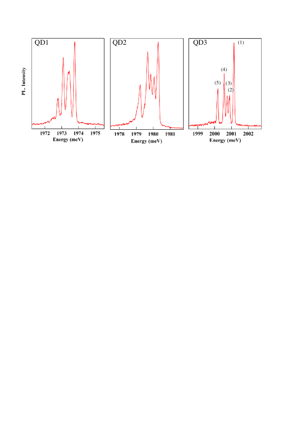
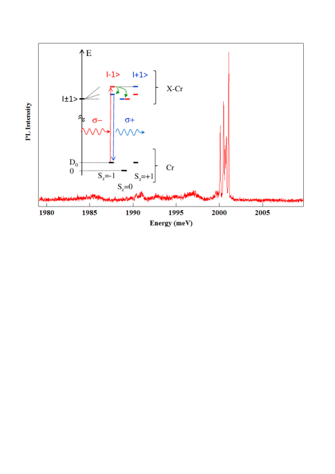
The low temperature (T=5K) PL of the neutral exciton coupled to a single Cr spin (X-Cr) of three individual Cr-doped QDs (QD1, QD2 and QD3) are reported in Figure 2. Three main emission lines are observed for X-Cr. The relative intensities of the lines and their splitting change from dot to dot. For some of the dots, a splitting of the central line is observed and an additional line appears on the low energy side of the X-Cr spectra. All these features result from the exchange coupling of the electron and hole spins with a single Cr spin.
When an electron-hole (e-h) pair is injected in a Cr-doped QD, the bright excitons are split by the exchange interaction between the spins of Cr and carriers. In flat self-assembled QDs, the heavy-holes and light-holes are separated in energy by the biaxial strain and the confinement. In a first approximation, the ground state in such QD is a pure heavy-hole (Jz=3/2) exciton and the exchange interaction with the Cr spin S is described by the spin Hamiltonian
| (10) |
with the electron spin and Jz the hole spin operator. IeCr and IhCr are, respectively, the exchange integrals of the electron and the hole spins with the Cr spin. These exchange energies depend on the exchange constant of the electrons of the Cr with the carriers in CdTe and on the overlap of the Cr atom with the confined carriers.
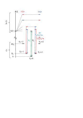
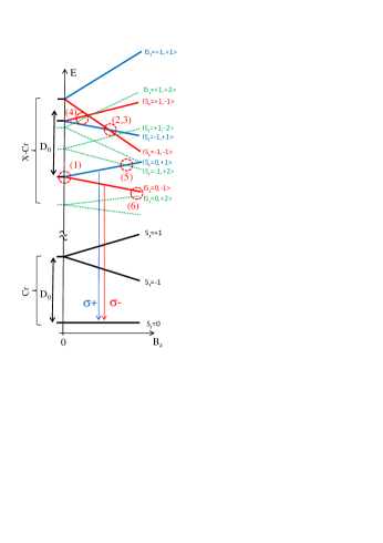
For highly strained CdTe/ZnTe QDs with a weak hole confinement, the strain induced energy splitting of the Cr spin is much larger than the exchange energy with the confined carriers (). The exchange interaction with the exciton acts as an effective magnetic field which further splits the Cr spins states Sz=1 and Sz=2. The resulting X-Cr energy levels are presented in Figure 3. The exciton recombination does not affect the Cr atom and its spin is conserved during the optical transitions. Consequently, the large strained induced splitting of the Cr spin is not directly observed in the optical spectra. However, at low temperature, the Cr spin thermalize on the low energy states Sz=0 and Sz=1. This leads to a PL dominated by three contributions: A central line corresponding to Sz=0 and the two outer lines associated with Sz=1 split by the exchange interaction with the carriers.
As presented in the case of QD3 in Figure4, most of the Cr-doped QDs exhibit a linear polarization dependence. The central line is split and linearly polarized along two orthogonal directions (lines (2) and (3)). As in non-magnetic QDs, this results from a coupling of the two bright excitons by (i) the long range e-h exchange interaction in QDs with an in-plane shape anisotropy and/or (ii) the short range exchange interaction in the presence of valence band mixing. This anisotropic e-h exchange interaction energy mixes the bright exciton associated with the same Cr spin state inducing an additional splitting between them. The mixing is maximum for the central bright exciton lines which are initially degenerated. The outer lines (lines (1) and (4)) are also partially linearly polarized but the influence of the e-h exchange interaction is here attenuated by the initial splitting of the bright excitons induced by the exchange interaction with the Cr spin .
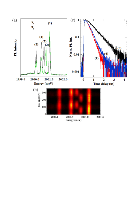
In many Cr-doped QDs, an additional line appears on the low energy side of the PL spectra at zero magnetic field. As presented in Figure 4 for QD3, this line presents a longer lifetime. It arises from a dark exciton (total angular momentum ) which acquires some oscillator strength by a mixing with a bright exciton interacting with the same Cr spin state Lafuente2016 . This dark/bright exciton mixing is induced by the e-h exchange interaction in a confining potential of low symmetry Zielinski2015 .
Let us note finally that in the presence of electrical doping and/or optical excitation, charge transfer from the Cr atom to the band of the semiconductor or to other localized levels may occur leading to changes in the shell configuration and in the charge states of the Cr. This is in particular the case for Cr in ZnTe where the donor and level Cr2+/3+ and the acceptor level Cr2+/1+ are both within the band gap. Such fluctuation of the charge state of a Cr atom has been observed optically for Cr atoms located in the ZnTe barriers close to a QD Besombes2019 . Fluctuation of the charge of the Cr between Cr2+ and Cr+ could also be possible for a Cr in CdTe as the acceptor level Cr2+/1+ is within the band gap close to the conduction band. Such fluctuation between a (S=2) and a (S=5/2) magnetic atom has never been identified until now in the spectra of individual QDs.
III.2 Magneto optical properties of Cr-doped quantum dots
The structure of the energy levels in QDs containing a Cr2+ ion is confirmed by the evolution of the PL spectra in magnetic field. The circularly polarized PL of QD1 and QD4 under a magnetic field applied along the QD growth axis are presented in Figure 5. Under a magnetic field the exciton states and are split by the Zeeman energy. This splitting can compensate the exciton splitting induced by the exchange interaction with the Cr (anti-crossing (1) at Bz=0 T in Figure 5(a)) Leger2005 . For QD1, this results in an anti-crossing of and excitons due to the e-h exchange interaction around Bz=6 T observed both in + and - polarizations (anti-crossing (2) and (3) in Figure 5(a)).
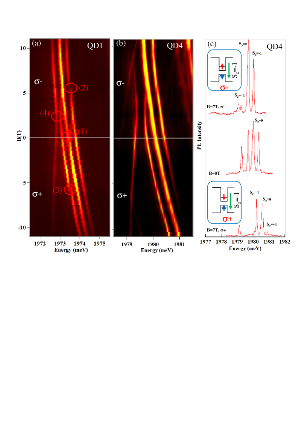
An anti-crossing of the low energy dark exciton with the bright excitons is observed under Bz in - polarization (anti-crossing (4) in Figure 5(a)). As illustrated in Figure 6 this anti-crossing arises from a mixing of the bright and dark excitons interacting with the same Cr spin state. Observed in - polarization, it corresponds to the mixing of the exciton states and coupled to the Cr spin Sz=-1. This dark/bright exciton coupling is induced by the e-h exchange interaction in a confining potential of reduced symmetry (lower than C2v) Zielinski2015 . In such symmetry, the dark excitons acquire an in-plane dipole moment which lead to possible optical recombination at zero magnetic field Bayer2002 as observed in QD3 and QD4. The oscillator strength of this ”dark exciton” increases as the initial splitting between and excitons is reduced by the magnetic field (Figure6).
At moderate excitation power, a variation under magnetic field of the intensity distribution between the high and low energy lines can be observed in some of the Cr-doped QDs (See QD4 in Figure 5). Under a magnetic field applied along the QD growth axis, a maximum of PL intensity is observed on the high energy side of the exciton-Cr spectra in polarization and on the low energy side in polarization. This change in the intensity distribution is more or less pronounced from one dot to another (see QD1 and QD4 in Figure 5) but always presents the same tendency and easier to observe at low excitation intensity Lafuente2018 . Such distribution, with a maximum of PL intensity on the high energy side in - polarization (which shifts to low energy under B0) and on the low energy side in + polarization, is identical to the one observed in CdTe/ZnTe QDs doped with a single Mn atom. In these systems, the hole-Mn exchange interaction is known to be anti-ferromagnetic Besombes2005 and approximately four times larger than the ferromagnetic electron-Mn exchange interaction.
Under a longitudinal magnetic field the Cr spin states S in the empty QD are split by the Zeeman energy with a Lande factor . Among the Zeeman doublet S, the Cr spin thermalizes on the lowest energy Cr spin state at low temperature. At moderate excitation power where the exciton-Cr PL intensity distribution is not dominated by the carriers-Cr spin-flips, this population distribution can be partially mapped on the exciton-Cr PL. When an unpolarized exciton is injected in the QD, the energy position of the most populated states with S, on the high energy or the low energy side of the exciton PL spectra, depends on the sign of the exciton-Cr exchange interaction. This exchange interaction results from the sum of the electron-Cr and hole-Cr exchange interactions.
The intensity distribution observed under magnetic field in the studied Cr-doped QDs (see QD4 in Figure5) shows that the exciton-Cr state is at high energy whereas the state is at low energy. This corresponds, for a CdTe/ZnTe QD, to an anti-ferromagnetic exchange interaction between the heavy-hole and the Cr spins. The sign of this interaction could however be different in bulk CdTe. For a CdTe QD in a ZnTe barrier, the biaxial strain can decrease the energy of the ground heavy hole levels, can become negative and the resulting exchange interaction can therefore be anti-ferromagnetic. The strain induced modification of the crystal field can also significantly influence the energy level of the orbital of the Cr and modify the kinetic exchange with the nearby hole spins at the top of the valence band. A more detailed model should be developed to properly describe the influence of the hybridisation in these strained and confined systems where the levels of the magnetic atom are close in energy with the edge of the valence band.
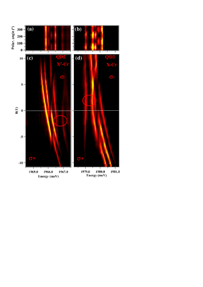
Investigating both the biexciton () and the exciton () in the same Cr-doped QD, we can also analyze the impact of the carrier-Cr interaction on the fine structure of the Cr spin. The magnetic field dependence of X2-Cr and X-Cr emissions in QD2 are presented as a contour plot in Figure 7(c) and (d) respectively. The PL under magnetic field of X-Cr and X2-Cr present a mirror symmetry. In particular, the dark/bright exciton mixing observed around Bz=2.5T on the low energy side of the PL in polarization for X-Cr is observed on the high energy side in polarization for X2-Cr (circles in Figure 7(c) and (d)).
III.3 Modeling of Cr-doped quantum dots
To estimate the relevant parameters of a the Cr-doped QDs from the optical spectra the, we calculated the magneto-optic behavior of Cr-doped QDs by diagonalizing the complete Hamiltonian of the electron-hole-Cr system. We consider the general case of QDs with a symmetry lower than C2v (truncated ellipsoidal lens for instance Zielinski2015 ), and take into account the influence of this reduced symmetry on the valence band and on the e-h exchange interaction.
The complete electron-hole-Cr Hamiltonian in a QD () can be separated into six parts:
| (11) |
describes the fine structure of the Cr atom and its dependence on local strain as presented in section 2.
describes the coupling of the electron and hole with the Cr spin. It reads
| (12) |
with and the exchange integrals of the electron () and hole () spins with the Cr spin ().
An external magnetic field couples via the standard Zeeman terms to both the Cr spin and carriers spins and a diamagnetic shift of the electron-hole pair can also be included resulting in
| (13) |
The electron-hole exchange interaction, , contains the short range and the long range parts. The short range contribution is a contact interaction which induces a splitting of the bright and dark excitons and, in the reduced symmetry of a zinc-blend crystal (), a coupling of the two dark excitons. The long range part also contributes to the bright-dark splitting by an energy . In QDs with C2v symmetry (ellipsoidal flat lenses for instance Zielinski2015 ) the long range part also induces a coupling between the bright excitons. Realistic self-assembled QDs have symmetries which can deviate quite substantially from the idealized shapes of circular or ellipsoidal lenses. For a symmetry (truncated ellipsoidal lens), additional terms coupling the dark and the bright excitons have to be included in the electron-hole exchange Hamiltonian. Following Ref. Zielinski2015 , the general form of the electron-hole exchange Hamiltonian in the heavy-hole exciton basis , , , for a low symmetry QD (Cs) is
| (18) |
The terms and , not present in symmetry C2v, give an in-plane dipole moment to the dark excitons Bayer2002 . The term which couples and excitons respectively is responsible for the dark-bright anti-crossing observed on the low energy side (lines (4) and (5)) of the emission of Cr-doped QDs.
The band Hamiltonian, , stands for the energy of the electrons (i.e. the band gap energy Eg), and the heavy-holes (hh) and light-holes (lh) energies () Leger2007 ; Besombes2014 . To describe the influence of a reduced symmetry of the QD on the valence band, we considered here the four lowest energy hole states with angular momentum . A general form of Hamiltonian describing the influence of shape or strain anisotropy on the valence band structure can be written in the basis () as:
| (19) |
Here, describes the heavy-hole / light-hole mixing induced by an anisotropy in the (xy) plane of the QD plane and takes into account an asymmetry in the plane containing the QD growth axis . The reduction of symmetry can come from the shape of the QD (Luttinger Hamiltonian) or the strain distribution (Bir and Pikus Hamiltonian). is the splitting between and which is controlled both by the in-plane biaxial strain and the confinement.
Considering only an in-plane anisotropy (), it follows from (19) that the valence band mixing couples the heavy-holes and the light-holes respectively. For such mixing, the isotropic part of the short range exchange interaction, which can be written in the form , couples the two bright excitons. This mixing is also responsible for a weak -polarized dipole matrix element of the dark excitons coming from the light-hole part of the hole wave function.
A deformation in a vertical plane ( term) couples the heavy-holes and the light-holes respectively. In this case, the short range electron-hole exchange interaction couples and exciton on one side and and exciton on the other side.
For a general description and as it was observed in Mn-doped QDs Besombes2005 ; Trojnar2013 ; Besombes2014 , we can also take into account the perturbation of the wave function of the exciton in the initial state of the optical transition by the hole-Cr exchange interaction. This perturbation depends on the value of the exchange energy between the Cr and hole spins and can be represented, using second order perturbation theory, by an effective spin Hamiltonian Besombes2005 ; Trojnar2013 ; Besombes2014
| (20) |
with .
| IeCr | IhCr | ||||||
| -30 | 220 | -800 | 200 | 200 | 50 | 0.05 | 0.05 |
| 2.2 | 2 | -1 | 0.4 | 1.5 | 25 | 20 |
Using the Hamiltonian of the excited state and the Hamiltonian of the ground state
| (21) |
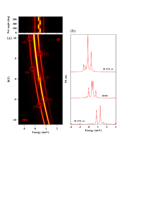
we can compute the spectrum of a QD containing a Cr atom. The occupation of the X-Cr levels is described by an effective spin temperature Teff and the optical transitions probabilities are obtained calculating the matrix elements where and Sz stands for the 8 possible exciton states (4 excitons and 4 excitons) and the Cr spin respectively. The resulting PL spectra calculated with the parameters listed in table 2 are presented in Figure8. The PL of X-Cr at zero field and its evolution in magnetic field can be qualitatively reproduced. In particular, the description of the spin states occupation by Teff is sufficient to reproduce the observed emission from the three low energy X-Cr levels (Cr spin states Sz=0 and Sz=1). The splitting of the central line at zero field (anti-crossing (1)) and the anti-crossings under magnetic field (anti-crossings (2) and (3) around Bz=6T for the Cr spin states Sz=+1 and anti-crossings (4) with the dark exciton around Bz=2T) are also well reproduced by the model.
This model also predicts an anti-crossing around Bz=5T, noted (5) in Figure8, caused by an electron-Cr flip-flop which is not observed in the experiments. Its position is controlled by and its width by . A low value of is required to keep the width of the anti-crossing smaller than the width of the PL lines. Finally an additional anti-crossing, labeled (6), appears in the model at high magnetic field in polarization. It is due to the mixing of bright and dark excitons associated with the same spin state of the Cr, in this case Sz=0. Such anti-crossing is observed in some of the Cr doped QDs, like QD4 in Figure5. Similar bright/dark mixing induced by the electron-hole exchange interaction in low symmetry QDs can also be observed in non-magnetic QDs Leger2007 .
The model reproduces quite well the main features of the magnetic field dependence of Cr-doped QDs, however the magnetic anisotropy cannot be precisely extracted from the comparison of the PL spectra with the model. Nevertheless, for , a wide anti-crossing due to a VBM induced hole-Cr flip-flop between the states and would appear for on the central line in polarization. larger than 4 meV would push the spin states at high energy and leads to a PL intensity on the central line (Sz=0) much larger than observed experimentally.
IV Resonant optical control and spin dynamics of an isolated Cr atom.
A Cr atom presents a large spin to strain coupling particularly promising for the realization of in nano-mechanical systems. For a practical use of this single spin system, one has to be able to prepare it and probe its dynamics.
IV.1 Resonant optical pumping of a single Cr spin
To initialize and read-out the Cr spin, we developed a two wavelengths pump-probe experiment. A circularly polarized single mode laser (resonant pump) tuned on a X-Cr level is used to pump the Cr spin (i.e. empty the Cr spin state under resonant excitation). Then, a second laser, tuned on an excited state of the QD (quasi-resonant probe), injects excitons independently of the Cr spin and drives the Cr to an effective spin temperature where the three ground states =0,1 are populated Lafuente2016 . By recording the PL of a X-Cr lines in circular polarization under this periodic sequence of excitation, we can monitor the time evolution of the population of a given Cr spin state (see Figure9 for the configuration of the excitation and detection).
The main features of the optical pumping experiment performed on a neutral QD (QD3 in Figure9) are presented in Figure 10(a). The QD is excited on the high energy state of X-Cr with photons (X-Cr state ). This excitation can only create an exciton in the dot if the Cr spin is =-1. An absorption followed by possible spin-flips of the Cr in the exchange field of the exciton progressively decreases the population of =-1. After this pumping sequence, the resonant pump is switched off and followed by the non-resonant probe.
A clear signature of the optical pumping appears in the time evolution of the PL intensity of the low energy bright exciton line (4). The PL of this line during the probe pulse, recorded in opposite circular polarization with the resonant pump, depends on the population of =-1. It strongly differs between the two pump-probe sequences where the resonant pump is on or off. The difference of intensity at the beginning of the probe pulse is a measurement of the efficiency of the pumping. The PL intensity transient during the probe pulse corresponds to a destruction of the non-equilibrium population distribution prepared by the pump. The speed of this spin heating process depends on the intensity of the probe laser. As expected for an increase of the Cr spin temperature, the population of the ground spin state =0 also decreases during the probe pulse. This decrease directly appears in the time evolution of the amplitude of the central X-Cr lines during the probe pulse (Detection of line (3) in Figure 10(a)). The increase of the population of =0 during the probe pulse shows that the population of =-1 has been partially transferred to =0 during the resonant pumping sequence.
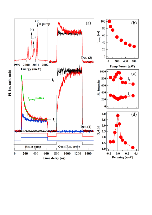
A more direct way to probe the optical pumping speed and efficiency is to monitor the time evolution of the PL during the resonant excitation by the pump pulse. Under resonant excitation on the high energy X-Cr line, an exciton spin-flip with conservation of the Cr spin can produce a PL on the low energy line LeGall2010 . In this process, the exciton flips its spin by emitting (or absorbing) an acoustic phonon. Such spin-flip is enhanced by the large acoustic phonon density of states at the energy of the inter-level splitting induced by the exchange interaction with the Cr spin which act as an effective magnetic field Tsitsishvili2003 ; Roszak2007 . The resulting weak resonant PL signal depends on the occupation of the Cr state =-1 and is used to monitor the time dependence of the spin selective absorption of the QD.
The time evolution of the PL of the low energy line of X-Cr (line (4)) under an excitation on the high energy line (1) is presented in Figure 10(a) for two different pump-probe sequences: probe on and probe off. When the probe laser is on, a large effective Cr spin temperature is established before each pumping pulse. The amplitude of the resonant PL is maximum at the beginning of the pump pulse () and progressively decreases. A decrease of the amplitude of about 80% is observed after a characteristic time in the tens of range. As expected for a spin optical pumping process, the characteristic time of the PL transient decreases with the increase of the pump laser intensity (Figure 10(b)) LeGall2010 . When the probe laser is off, the initial amplitude of the PL transient during the pump pulse is significantly weaker. This decrease is a consequence of the conservation of the out of equilibrium Cr spin distribution during the dark time between two consecutive pumping pulses.
The steady state resonant PL intensity reached at the end of the pump pulse () depends on the optical pumping efficiency which is controlled by the ratio of the spin-flip rate for the Cr spin in the exchange field of the exciton and the relaxation of the Cr spin in the absence of carriers in the dot. However, even with cross-circularly polarized excitation/detection, this steady state PL can also contain a weak contribution from an absorption in the acoustic phonon sideband of the low energy line (4) Besombes2001 . Figure 10(c) presents the amplitude of the resonant PL detected on line (4) for a detuning of the pump around the high energy line (1). A resonance is observed in the initial amplitude of the PL. It reflects the energy and excitation power dependence of the absorption of the QD. A small decrease of the steady state PL is also observed at the resonance. As displayed in Figure 10(d), the corresponding normalized amplitude of the pumping transient, , presents a clear resonant behavior demonstrating the excitation energy dependence of the optical pumping process. The width of the resonance () is the width of the QD’s absorption broadened by the fluctuating environment Sallen2011 .
IV.2 Cr spin relaxation in the dark
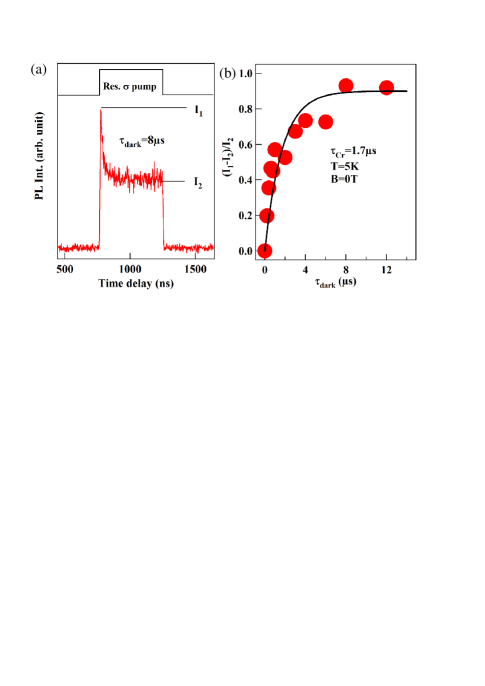
With this resonant optical pumping technique used to prepare and read-out the Cr spin, we performed pump-probe experiments to observe its relaxation time in the absence of carriers (Figure 11). A non-equilibrium distribution of the Cr spin population is prepared with a circularly polarized resonant pump pulse on the high energy X-Cr line (1). The pump laser is then switched off, and switched on again after a dark time . The amplitude of the pumping transient observed on the resonant PL of the low energy line (4) depends on the Cr spin relaxation during . As presented in Figure 11(b), the amplitude of the transient is fully restored after a dark time of about 10 s showing that after this delay the Cr spin is in equilibrium with the lattice temperature (T=5K). Let us note, however, that the initial amplitude of the pumping transient in this case is weaker than the one observed after a non-resonant probe pulse (Figure 11(a)). This means that the non-resonant optical excitation drives the Cr spin to an effective temperature much larger than the lattice temperature.
These measurements reveal a significantly different Cr spin-flip times under optical excitation (tens of nanosecond range) and in the dark (microseconds range). The fast Cr spin-flip under optical excitation can be due to the interaction with carriers (exchange induced Cr spin flips Cao2011 ) but can also be induced by the interaction with non-equilibrium acoustic phonons created during the energy relaxation of the injected carriers. Both mechanisms probably contribute to the Cr spin heating.
IV.3 Dynamics under optical excitation and mechanism of optical pumping for a Cr spin
In order to identify the main mechanism responsible for the optical pumping, we analyzed the PL intensity distribution under resonant excitation Lafuente2018 . We have seen that under circularly polarized resonant excitation of the high energy X-Cr line (1), a weak PL is observed in cross-circular polarization on the low energy bright exciton line (4) after a spin-flip of the exciton conserving the Cr spin. In this experimental configuration the same spin state of the Cr is excited and detected (see the energy level diagram presented in Figure 9(a)). The intensity transient observed during the resonant PL directly reflects the pumping of the Cr spin state under excitation (either or ).
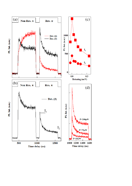
However, as presented in Figure12(a), during this resonant pumping process a luminescence is also observed on the central lines (2) and (3) (linearly polarized bright excitons resulting from the mixing of and ). This resonant PL presents a transient with a similar time scale and amplitude as the one detected on the low energy line (4). The steady state level of the resonant PL detected on is however much lager than for a detection on the low energy bright exciton. This steady state PL intensity is strongly reduced under cross linearly polarized excitation and detection (figure 12(b)).
The central line (2) and (3) are linearly polarized along two orthogonal directions. For a circularly polarized excitation on the high energy side of these transitions and for a cross-circularly polarized detection, a weak absorption in the acoustic phonon sideband Besombes2001 is expected to induce some resonant PL. However, the presence of the intensity transient due to the pumping of the resonantly excited spin states shows that there is also an efficient population transfer between the high energy bright excitons ( or ) created during the resonant optical excitation and the lower energy bright exciton states ( or ).
For a cross-linearly polarized excitation and detection, the absorption in the acoustic phonon side-band is strongly reduced. The pumping transient resulting from an absorption on the states and a transfer toward dominates the resonant PL. This spin-flip transfer is confirmed by the excitation energy and power dependence of the resonant PL signal. The PL intensity on line (3) presents a resonant behavior when scanning the pump laser around the high energy line (1) (Figure 12(c)). As expected for an optical pumping process, the time scale of the PL transient is also significantly reduced with the increase of the excitation intensity (Figure 12(d))).
This efficient transfer towards during the resonant optical pumping process is also observed in the evolution of the PL intensity during the non-resonant probe (heating) pulse. As expected after a resonant pumping of the spin states , their population re-increase during the non-resonant heating pulse. Simultaneously, a significant decrease of the intensity of the line (3) is observed both for a circularly or a linearly polarized detection (figure 12(a) and (b)). This decrease corresponds to a decrease of the population of =0 during the heating process showing that a significant part of the Cr spin population has been transferred to =0 during the resonant optical pumping.
A fast hole-Cr flip-flop can explain an efficient transfer of population from the exciton-Cr levels S towards the low energy states S. The proposed relaxation path is illustrated in the energy level scheme presented in figure 13 which displays the possible relaxation channels involving a hole-Cr flip-flop for an initial excitation of the bright excitons coupled with .
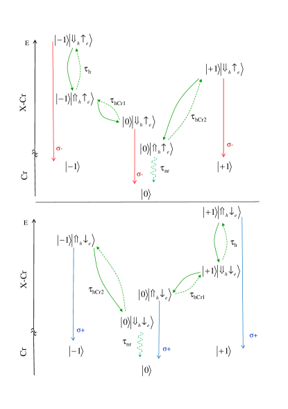
Starting from the low energy bright excitons or , a hole-Cr flip-flop with conservation of the electron spin can directly transfer the population towards the dark excitons associated with S with a spin flip time . With the same mechanism, a direct transfer is possible from the low energy dark excitons or , to the bright excitons associated with S with a spin flip time (See figure 13).
Starting from the high energy bright excitons or , a hole-Cr flip-flop is unlikely as it would involve a transfer toward the high energy Cr spin states . However, a spin flip of the hole with characteristic time conserving the spin of the Cr can induce a transfer to the low energy dark excitons or . Such spin-flip from a bright to a dark exciton can occur in QDs in a time-scale of a few nanoseconds Cao2011 . A hole-Cr flip-flop in a timescale can then transfer the population from these dark excitons to the Sz=0 bright exciton which then recombines optically (See figure 13).
From the hight energy dark excitons or a hole-Cr flip-flop is also unlikely (transfer toward the high energy Cr spin states ). However these states are coupled by a hole spin-flip to the nearby low energy bright excitons or and can then follow this path to be transferred towards .
The spin relaxation channels involving a transfer from the dark exciton with to the lower energy bright excitons are made irreversible by the fast ( 250 ps) radiative recombination of the final low energy exciton state. This unusual situation with some of the bright excitons at lower energy than the dark ones can induce an out of equilibrium distribution on the Cr spin states with an enhanced population of the Sz=0 ground state. The transfer mechanism involving a hole-Cr flip-flop is enhanced by the increase of the probability of presence of an exciton in the QD. This can be observed in the excitation power dependence of the distribution of the non-resonant PL intensity Lafuente2018 .
Under resonant excitation on the hight energy levels of X-Cr (line (1)), a spin flip of the hole followed by a fast hole-Cr flip-flops can explain the observed transfer of excitation toward the bright excitons associated with . This process which efficiently changes the Cr spin is the likely to be the main source for the resonant optical pumping demonstrated in Cr-doped QDs Lafuente2017Cr .
IV.4 Phonon induced hole-Cr flip-flops
The time-scale of the hole-Cr flip-flops in a Cr-doped QD induced by the interaction with the continuum of bulk acoustic phonons can be estimated using the Fermi golden rule. The spin-flip process that we consider here is based on the interplay of the hole-magnetic atom exchange interaction and the interaction with the strain field of acoustic phonons Lafuente2017Mn . Similar models, combining exchange interaction and coupling with acoustic phonons, where developed to explain the exciton spin relaxation in QDs Tsitsishvili2003 ; Roszak2007 .
Let us consider the two X-Cr states and that can be coupled via a hole-Cr flip-flop. The non-diagonal terms of the hole-Cr exchange interaction couples the heavy-holes and light-holes excitons levels separated in energy by through a hole-Cr flip-flop. To the first order in , the two perturbed heavy-hole exciton ground states can be written:
| (22) |
where we neglect the exchange energy shifts of the exciton-Cr levels much smaller than .
The strain field produced by acoustic phonon vibrations couples the perturbed exciton-Cr states through the Hamiltonian term:
| (23) |
with a strain-dependent non-diagonal term of the Bir-Pikus Hamiltonian kp . The coupling of these exciton-Cr states is then a result of an interplay between the hole-Cr exchange interaction and the strain field of acoustic phonons.
In analogy with the model developed in reference (36) to describe hole-Mn flip-flops in positively charged Mn-doped QDs, the decay rate associated with the emission of phonons which is deduced from the Fermi golden rule and the matrix element (23) can be written:
| (24) | |||||
where the summation is taken over the acoustic phonon branches (one longitudinal and two transverse ) of corresponding sound velocity cλ. The geometrical form factors for each phonon branch appearing in (24), , are given by , and .
Numerical calculation of the hole-Cr spin-flip time in a CdTe QD are presented in figure 14. We used in the calculation a Gaussian wave function for the hole with in-plane and z-direction parameters and respectively, the material parameters of CdTe and typical parameters of self-assembled CdTe/ZnTe QDs listed in table 3.
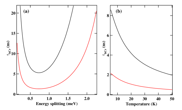
The calculated spin relaxation time strongly depends on the energy splitting between the X-Cr states involved in the hole-Cr flip-flops (figure 14(a)). This dependence on the high energy side is controlled by the size of the hole wave function which limits the wave vector of the acoustic phonons that can interact with the hole. The calculated spin-flip time can be in the nanosecond range for an energy splitting between 0.5 meV and 2 meV. In the studied Cr-doped QDs, the splitting between the low energy dark excitons states or and the bright excitons with , which are coupled by a hole-Cr flip-flop, is typically in the 1 meV range. A spin-flip time of a few ns can then be expected.
| CdTe | ||
| Deformation potential constants | 1.0 eV | |
| 4.4 eV | ||
| Longitudinal sound speed | cl | 3300 m/s |
| Transverse sound speed | ct | 1800 m/s |
| Density | 5860 kg/m3 | |
| Quantum dot | ||
| Cr-hole exchange energy | IhCr | 0.22 meV |
| hh-lh exciton splitting | 25 or 50 meV | |
| Hole wave function widths: | ||
| - in plane | l⊥ | 3.0 nm |
| - z direction | lz | 1.25 nm |
For the low energy bright excitons or and the dark excitons states with also coupled by hole-Cr flip-flops, their energy splitting is larger than 3 meV and the spin-flip rates are expected to be significantly reduced. For the high energy Cr spins states, S, the energy splitting is typically larger than 10 meV and the corresponding flip-flops induced by the discussed mechanism can be neglected.
The estimated hole-Cr flip-flop time is also strongly sensitive to the effective energy splitting between heavy-hole and light-hole . This simple parameter is used in our model for an effective description of the valence band mixing. It can describe complex effects such as a coupling of the confined heavy-hole with ground state light-holes in the barriers Michler2003 or effective reduction of heavy-hole/light-hole splitting due to a presence of a dense manifold of heavy-hole like QD states lying between the confined heavy-hole and light-hole levels Bester2015 . This parameter can significantly change from dot to dot and modify the hole-Cr flip-flop time.
The calculated hole-Cr flip-flop rate also depends on the temperature through the stimulated emission of acoustic phonons. For an energy splitting of 1 meV the spin flip rate involving the emission of phonons is increased by a factor of about four by increasing the temperature from 5K to 50K (figure 14(b)). Such enhancement of the hole-Cr spin-flip rate can not only be induced by an increase of the lattice temperature but also, as in our experiments, by the presence of non-equilibrium phonons that are generated by the optical excitation inside or in the vicinity of the QD.
This calculated short flip-flop time in the range, is consistent with the initialization time measured in resonant optical pumping experiments and controls the spin dynamics under resonant excitation.
IV.5 Optical Stark effect on an individual Cr spin
The resonant optical excitation on a X-Cr line can also be used to tune the energy of any Cr spin state through the optical Stark effect LeGall2011 ; Xu2007 ; Muller2008 . Such energy shift could be exploited to control the coherent dynamics of the magnetic atom Jamet2013 ; Reiter2013 . This optical control technique is presented in Figure 15. When a high intensity single mode laser is tuned to the high energy line of X-Cr in polarization (X-Cr state ), a splitting is observed in polarization in the PL of the two low energy lines produced by a second non-resonant laser.
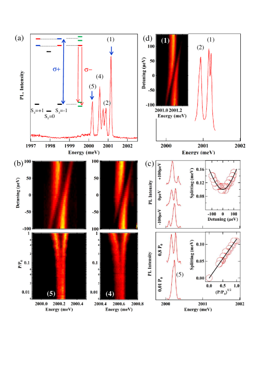
At high excitation intensity, a strong coupling with the resonant laser field mixes the states with a Cr spin component =-1 in the presence (X-Cr) or absence (Cr alone) of the exciton. In the ground state of the QD (Cr alone) two hybrid matter-field states are created (inset of Figure 15(a)). Their splitting, , depends on the energy detuning of the laser and on its intensity through the Rabi energy Boyle2009 . It can be observed in the PL of all the X-Cr states associated with =-1: the low energy bright exciton state (line (4)) and the dark exciton (line (5)), close in energy to the bright exciton and which acquires some oscillator strength through the exciton mixing induced by the electron-hole exchange interaction in a low symmetry QD Lafuente2016 .
The splitting measured on line (5) for a resonant excitation on line (1) is plotted as a function of the square root of the resonant laser intensity in Figure 15(c) and shows that, as expected for a two level system, it linearly depends on the laser field strength. The Rabi splitting can reach 150 at high excitation power. As the pump laser is detuned, the optically active transitions asymptotically approaches the original excitonic transitions where the remaining offset is the optical Stark shift.
A resonant laser permits to address any spin state of the Cr and selectively shift its energy. For instance, as presented in Figure 15(d), a + excitation on the dark exciton state (5) induces a splitting of the high energy line (1) in - polarization (state ) without affecting the central line (2). This shows that such resonant excitation can be used to tune the energy of =+1 without affecting =0. The energy tuning induced by a coherent optical driving is particularly interesting for the control of the Cr spin states =1. These states could be efficiently mixed by applied weak anisotropic in-plane strain through a fine structure term of the form Lafuente2016 . A relative shift of the energy of =+1 or =-1 by a resonant optical excitation would affect their coupling and consequently the Cr spin coherent dynamics.
Future applications of Cr as a spin in hybrid nano-mechanical systems Pigeau2015 ; Barfuss2015 will exploit the efficient mixing of the Cr spin states =+1 and =-1 induced by anisotropic in-plane strain. The resulting mixed spin states, together with an exciton, form an optical three level system. A coherent optical driving of this level structure opens the possibility of using coherent spectroscopy techniques such as coherent population trapping Houel2014 for a sensitive probing of the splitting of the =+1 and =-1 induced by the local strain at the atom location. The strain field that could be probed with this technique will depend on the coherence time of the Cr spin .
V Perspectives: a Cr atom as a spin qubit in hybrid spin-mechanical systems.
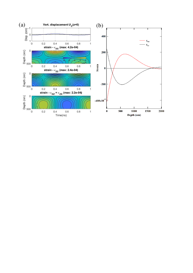
It has been shown recently that an individual spin can be used as a to interact with the motion of a nano-mechanical oscillator and probe its position, cool it down or prepare non-classical state of the mechanical motion Lee2017 . It has been also demonstrated theoretically that the coupling of two or more localized spins with the same mode of a mechanical oscillator could be used to induce long range coherent coupling between spins Bennett2013 , a usually difficult task to achieve with spins in solid state systems. Among mechanical systems, Surface Acoustic Wave (SAW) i.e. phonons propagating at the surface of a solid, are particularly promising. SAW can coherently propagate over long distances at the surface of a solid state device, they can be guided or confined in acoustic wave-guide or acoustic cavities and they can interact with different kinds of . They are in particular proposed as efficient quantum bus between dissimilar Schuetz2015 ; Lemonde2018 . In the case of spin , the performance of SAW based nano-mechanical devices will be enhanced by the use of localized spins with large intrinsic spin to strain couplings. Cr is in that sense particularly promising. As we have seen in section 2.1, in-plane strain oriented along the [110] direction () will be strongly coupled to the spin degree of freedom of a Cr.
Large in-plane dynamical strains at a precisely defined frequency can be generated by propagating SAW and SAW device technology also offers simple approach for fabricating high quality factor mechanical resonators. Following the model presented in ref. Schuetz2015 , the strain profile for a SAW propagating along the [110] direction of a zinc-blend material can be calculated analytically. The strain profile for a SAW in the GHz range propagating in the surface of ZnTe along [110] ( direction) is presented in Figure 16. Large oscillating in-plane strain oriented along the direction of propagation of the SAW can be obtained near the surface of the sample. This strain field can be used to interact with a Cr spin located at less than 100 nm from the surface. SAW also produce close to the surface a component of the strain that modifies the static magnetic anisotropy already present for a Cr in a CdTE/ZnTe QD.
To generate SAW on a Cr-doped QD, inter-digitated transducer (IDT) can be used to convert a radio-frequency signal into a mechanical motion at a well defined frequency through the inverse piezoelectric effect. The electromechanical coupling in an IDT depends on the square of the piezoelectric coefficients . Compared to GaAs where SAW propagating along [110] direction can be directly generated with an IDT, ZnTe has a very weak piezo-electric coefficient . A layer of a piezo-electric material, like hexagonal ZnO with its axis perpendicular to the sample surface, can be used to enhance the electromechanical coupling and the performances of the transducer Thevenard2014 .
In the presence of an oscillating in-plane strain field along the [110] direction, , the non-diagonal coupling term of the spin to strain Hamiltonian (7) for Cr becomes:
| (25) |
and the complete spin to strain Hamiltonian of Cr simplifies to
| (26) |
where we defined the parallel and perpendicular spin to strain susceptibility. A value of can be expected for a Cr atom in CdTe, at least two orders of magnitude larger than for NV centers in diamond where has been reported Barfuss2015 .
For small displacements, the strain is linear and we can quantize the perpendicular strain field . The corresponding strain coupling Hamiltonian takes the general form:
| (27) |
where is the transverse single phonon strain coupling strength and () the raising (lowering) operators for phonons.
In the situation where the coupling strength between the and the mechanical oscillator is much smaller than the and oscillator frequency, it is a good approximation to drop the counter rotating terms. This is the standard rotating wave approximation and the interacting Hamiltonian takes the form:
| (28) |
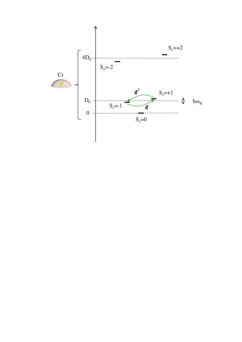
For Cr in a strained QD where the spin states S, S and S are split by a large magnetic anisotropy , we can focus on the two-level spin subspace only and assume that mechanically induced transitions to state or are not allowed due to the large zero field splitting (see Figure 17). For a given spin, we write Pauli operators and . Within this two-level subspace and within the rotating wave approximation, the interaction for a single spin with the strain field takes on the generic Jaynes-Cummings form
| (29) |
where a magnetic field parallel to the axis has been introduced to split the Cr spin levels by (with ). This magnetic field allows to adjust the energy of the spin to the energy of a phonon of the SAW mode . Under this usual description common to many systems, the dynamics of the Cr spin can be obtained in closed-form.
For a coherent phonon field at frequency (typically the one produced by a propagating SAW) tuned on resonance with the transition between the spin states, the spin to strain coupling can be rewritten
| (30) |
Where , the Raby energy, describes the amplitude of the strain drive. Dynamical anisotropic in-plane strain provided by the SAW Schuetz2015 could then be used for a direct coherent control of the spin under longitudinal magnetic field Macquarrie2015 . Such mechanical coherent control could be probed with the resonant optical pumping technique presented in the previous sections.
At high SAW excitation or in a SAW cavity, the large spin to strain coupling of Cr should permit to obtain a Rabi energy of the order of magnitude of the energy. In this coupling regime, called the strong driving regime, the rotating wave approximation is no longer valid and the response of the two-level system to the driving field is the source of many interesting phenomena which have not been studied in details until now.
SAW pulses (typically in the hundred ns range), could be used for a mechanical determination of the dynamical spin to strain coupling and the coherence time of the spin . This will permit to determine the coupling regime that could be reached between a SAW cavity and a Cr spin. In particular, the strong coupling regime could probably be reached for an ensemble of individual Cr spins and the fundamental mode of a SAW cavity. For a detuned cavity and two distinct Cr-doped QDs coupled to the same phonon mode of a SAW cavity, the mechanical motion can be used to induce a long distance spin-spin coupling Bennett2013 .
VI Conclusion
We demonstrated that the spin of a Cr atom in a semiconductor can be probed and controlled optically. In self-assembled QDs, the fine structure of the atom is dominated by a large magnetic anisotropy induced by bi-axial strain in the plane of the QDs. Resonant optical excitation can be used to control the spin of the atom. The Cr spin can be initialized by optical pumping, readout through the resonant PL of the QD and the energy of any spin state can tuned by the optical Stark effect. The spin relaxation of the Cr atom in the absence of optical excitation remains in the range at low temperature. The relaxation of a Cr spin in the exchange field of an exciton is however much faster and dominated by spin flips induced by an interplay of the hole-Cr exchange interaction and the interaction with acoustic phonons. The presence of these hole-Cr flip-flops taking place in a few ns explains the efficient optical pumping observed under resonant excitation.
The S spin states of the Cr can form a spin with a large spin to strain coupling. The possible optical control makes Cr a promising platform to study the interaction of the spin with SAW which are proposed as efficient quantum bus between different kinds of .
Acknowledgements
The work was supported by the French ANR project MechaSpin (ANR-17-CE24-0024) and CNRS PICS contract No 7463. V.T. acknowledges support from EU Marie Curie grant No 754303. The work in Tsukuba has been supported by the Grants-in-Aid for Scientific Research on Innovative Areas ”Science of Hybrid Quantum Systems” and for challenging Exploratory Research.
References
References
- (1) M. Veldhorst, C. H. Yang, J. C. C. Hwang, W. Huang, J. P. Dehollain, J. T.Muhonen, S. Simmons,A. Laucht, F. E. Hudson, K. M. Itoh, A. Morello, A. S. Dzurak, Nature (London) 526, 410 (2015).
- (2) S. Schmitt, T. Gefen, F. M. Stürner, T. Unden, G. Wolff, C. Müller, J. Scheuer, B. Naydenov, M. Markham, S. Pezzagna, J. Meijer, I. Schwarz, M. Plenio, A. Retzker, L. P. McGuinness, F. Jelezko, Science 356, 832 (2017)
- (3) L. Besombes, Y. Leger, L. Maingault, D. Ferrand, H. Mariette, J. Cibert, Phys. Rev. Lett. 93, 207403 (2004).
- (4) M. Goryca, T. Kazimierczuk, M. Nawrocki, A. Golnik, J. A. Gaj, P. Kossacki, P. Wojnar, G. Karczewski, Phys. Rev. Lett. 103, 087401 (2009).
- (5) C. Le Gall, L. Besombes, H. Boukari, R. Kolodka, J. Cibert, H. Mariette, Phys. Rev. Lett. 102, 127402 (2009).
- (6) C. Le Gall, R. S. Kolodka, C. Cao, H. Boukari, H. Mariette, J. Fernandez-Rossier, L. Besombes, Phys. Rev. B 81, 245315 (2010).
- (7) C. Le Gall, A. Brunetti, H. Boukari, L. Besombes, Phys. Rev. Lett. 107, 057401 (2011).
- (8) L. Besombes, C.L. Cao, S. Jamet, H. Boukari, J. Fernandez-Rossier, Phys. Rev. B 86, 165306 (2012).
- (9) A. Kudelski, A. Lemaitre, A. Miard, P. Voisin, T.C.M. Graham, R.J. Warburton, O. Krebs, Phys. Rev. Lett. 99, 247209 (2007).
- (10) O. Krebs, A. Lemaitre, Phys. Rev. Lett. 111, 187401 (2013).
- (11) A. O. Govorov, A. V. Kalameitsev, Phys. Rev. B 71, 035338 (2005).
- (12) D. E. Reiter, V. M. Axt, T. Kuhn, Phys. Rev. B 87, 115430 (2013).
- (13) J. Kobak, T. Smolenski, M. Goryca, M. Papaj, K. Gietka, A. Bogucki, M. Koperski, J.-G. Rousset, J. Suffczynski, E. Janik, M. Nawrocki, A. Golnik, P. Kossacki, W. Pacuski, Nature Communications 5, 3191 (2014).
- (14) T. Smolenski, T. Kazimierczuk, J. Kobak, M. Goryca, A. Golnik, P. Kossacki, W. Pacuski, Nature Communications 7, 10484 (2016).
- (15) A. Lafuente-Sampietro, H. Utsumi, H. Boukari, S. Kuroda, L. Besombes, Phys. Rev. B 93, 161301(R) (2016).
- (16) J.T. Vallin and G.D. Watkins, Phys. Rev. B 9, 2051 (1974).
- (17) B. Pigeau, S. Rohr, L. Mercier de Lepinay, A. Gloppe, V. Jacques, O. Arcizet, Nature Communications 6, 8603 (2015).
- (18) E.R. MacQuarrie, T.A. Gosavi, A.M. Moehle, N.R. Jungwirth, S.A. Bhave, G.D. Fuchs, Optica 2, 233 (2015).
- (19) J. Teissier, A. Barfuss, P. Appel, E. Neu, P. Maletinsky, Phys. Rev. Lett. 113, 020503 (2014).
- (20) A. Lafuente-Sampietro, H. Boukari and L. Besombes, Phys. Rev. B 92, 081305(R) (2015)
- (21) D. Lee, K. W. Lee, J. V. Cady, P. Ovartchaiyapong, A.C. Bleszynski Jayich, J. Opt 19, 033001 (2017).
- (22) P. Rabl, S.J. Kolkowitz, F.H.L. Koppens, J.G.E. Harris, P. Zoller, M.D. Lukin, Nature Physics 6, 602 (2010).
- (23) P. Ovartchaiyapong, K. W. Lee, B. A. Myers, A. C. Bleszynski Jayich, Nature Communications 5, 4429 (2014).
- (24) M.J.A. Schuetz, E.M. Kessler, G. Giedke, L.M.K. Vandersypen, M.D. Lukin, and J.I. Cirac, Phys. Rev. X 5, 031031 (2015)
- (25) M. Brousseau, Les defauts ponctuels dans les semiconducteurs, Les Editions de Physiques (1988).
- (26) M. Goryca, M. Koperski, P. Wojnar, T. Smolensky, T. Kaimierczuk, A. Golnik, P. Kossacki, Phys. Rev. Lett. 113, 227202 (2014).
- (27) S. Jamet, H. Boukari, L. Besombes, Phys. Rev. B 87, 245306 (2013).
- (28) P. Kacman, Semicond. Sci. Technol. 16, R25 (2001).
- (29) J. Kossut and W. Dobrowolski, Handbook of magnetic materials, Vol.7, chap.4, Edited by K.H.J. Buschow, Elsevier Science Publisher (1993).
- (30) J.K. Furdyna, J. Appl. Pphys 64, R29 (1988).
- (31) J. Blinowski, P. Kacman, Phys. Rev. B 46, 12298 (1992).
- (32) J. Blinowski, P. Kacman, J.A. Majewsky, Journal of Crystal Growth 159, 972 (1996).
- (33) S. Kuroda, N. Nishizawa, K. Takita, M. Mitome, Y. Bando, K. Osuch, T. Dietl, Nature Materials 6, 440 (2007).
- (34) A. Continenza and S. Massidda, Phys. Rev. B 50, 11949 (1994).
- (35) E. Rzepka, Y. Marfaing, M. Cuniot and R. Triboulet, Materials Science and Engineering B16, 262 (1993)
- (36) P. Wojnar, C. Bougerol, E. Bellet-Amalric, L. Besombes, H. Mariette, H. Boukari, J. Crystal Growth 335, 28 (2011).
- (37) B. Varghese, H. Boukari, L. Besombes, Phys. Rev. B 90, 115307 (2014).
- (38) M. Zielinski, Y. Don and D. Gershoni, Phys. Rev. B 91, 085403 (2015).
- (39) L. Besombes, H. Boukari, V. Tiwari, A. Lafuente-Sampietro, M. Sunaga, K. Makita, S. Kuroda, Phys. Rev. B xxxx (2009).
- (40) Y. Leger, L. Besombes, L. Maingault, D. Ferrand, H. Mariette, Phys. Rev. Lett. 95, 047403 (2005).
- (41) M. Bayer, G. Ortner, O. Stern, A. Kuther, A.A. Gorbunov, A. Forchel, P. Hawrylak, S. Fafard, K. Hinzer, T.L. Reinecke, S.N. Walck, J.P. Reithmaier, F. Klopf, F. Schafer, Phys. Rev. B 65, 195315 (2002).
- (42) Y. Leger, L. Besombes, L. Maingault, H. Mariette, Phys. Rev. B 76, 045331 (2007).
- (43) L. Besombes, Y. Leger, L. Maingault, D. Ferrand, H. Mariette, J. Cibert, Phys. Rev. B 71, 161307(R) (2005).
- (44) A. H. Trojnar, M. Korkusinski, U. C. Mendes, M. Goryca, M. Koperski, T. Smolenski, P. Kossacki, P. Wojnar, P. Hawrylak, Phys. Rev. B 87, 205311 (2013).
- (45) E. Tsitsishvili, R. V. Baltz, H. Kalt, Phys. Rev. B 67, 205330 (2003).
- (46) K. Roszak, V.M. Axt, T. Kuhn, P. Machnikowski, Phys. Rev. B 76, 195324 (2007).
- (47) Lok C. Lew Yan Voon, Morten Willatzen, The k.p method (Springer, Berlin 2009).
- (48) G. Sallen, A. Tribu, T. Aichele, R. Andre, L. Besombes, C. Bougerol, M. Richard, S. Tatarenko, K. Kheng, J.-Ph. Poizat, Phys. Rev. B 84, 041405(R) (2011).
- (49) C.L. Cao, L .Besombes, J. Fernandez-Rossier, Phys. Rev. B 84 (20), 205305 (2011)
- (50) A. Lafuente-Sampietro, H. Utsumi, H. Boukari, S. Kuroda, and L. Besombes, Phys. Rev. B 95, 035303 (2017).
- (51) A. Lafuente-Sampietro, H. Boukari, and L. Besombes, Phys. Rev. B 95, 245308 (2017).
- (52) A. Lafuente-Sampietro, H. Utsumi, M. Sunaga, K. Makita, H. Boukari, S. Kuroda, L. Besombes, Physical Review B. 97, 155301 (2018).
- (53) L. Besombes, K. Kheng, L. Marsal, H. Mariette, Phys. Rev. B 63, 155307 (2001).
- (54) S. Adachi, Properties of group IV, III-V and II-VI semiconductors (John Wiley and Sons Ltd, Chichester, 2005).
- (55) P. Michler, Single quantum dots fundamentals, applications and new concepts (Springer, Berlin, 2003).
- (56) J-W. Luo, G. Bester, A. Zunger, Phys. Rev. B 92, 165301 (2015).
- (57) X. Xu, B. Sun, P. R. Berman, D. G. Steel, A. S. Bracker, D. Gammon, L. J. Sham, Science 317, 929 (2007).
- (58) A. Muller,W. Fang, J. Lawall, G. S. Solomon, Phys. Rev. Lett. 101, 027401 (2008).
- (59) S.J. Boyle, A.J. Ramsay, A.M. Fox, M.S. Skolnick, A.P. Heberle, M. Hopkinson, Phys. Rev. Lett. 102, 207401 (2009).
- (60) J. Houel, J. H. Prechtel, A. V. Kuhlmann, D. Brunner, C. E. Kuklewicz, B. D. Gerardot, N. G. Stoltz, P. M. Petroff, R. J. Warburton, Phys. Rev. Lett. 112, 107401 (2014).
- (61) S.D. Bennett, N.Y. Yao, J. Otterbach, P. Zoller, P. Rabl, M.D. Lukin, Phys. Rev. Lett. 110, 156402 (2013).
- (62) L. Thevenard, C. Gourdon, J.Y. Prieur, H.J. von Bardeleben, S. Vincent, L. Becerra, L. Largeau, and J. Y Duquesne, Phys. Rev. B 90, 094401 (2014).
- (63) A. Barfuss, J. Teissier, E. Neu, A. Nunnenkamp, P. Maletinsky, Nature Physics 11, 820 (2015).
- (64) M.-A. Lemonde, S. Meesala, A. Sipahigil, M.J.A. Schuetz, M.D. Lukin, M. Loncar, P. Rabl, Phys. Rev. Lett. 120, 213603 (2018).